N89-MM230MIEEE 802.11b/g Bluetooth 2.0+ EDR and GPS MiniCard
CyberTAN Technology Inc.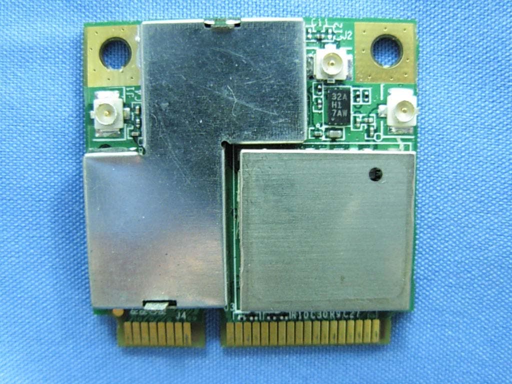
Click to zoom
Application Details
- Equipment Class
- DSS - Part 15 Spread Spectrum Transmitter
- Date of Grant
- Jan 30, 2008
- Application Purpose
- Original Equipment
- Date of Application
- Jan 28, 2008
- Equipment Note
- IEEE 802.11b/g Bluetooth 2.0+ EDR and GPS MiniCard
- Frequency Range
- 2402.00000000 - 2480.00000000
- Company
- CyberTAN Technology Inc.
- Country
- Taiwan
Documents & Files
Document Text
Text extracted from the exhibit documents filed with the FCC. Open a document above to read the original.
Users Manual
MM230-M MiniCard MM230-M IEEE 802.11b/g Bluetooth 2.0+ EDR and GPS MiniCard User Manual Rev 0.1 MM230-M MiniCard National Communications Commission Interference Statement This equipment includes wireless RF module, and must be labeled in a visible area with the following: Contains NCC ID: XXXyyyLPDzzzz-x MM230-M MiniCard ii Table of contents Introduction.........................................................1 Hardware Installation....................................................4 Using the Wireless Utility.........................................5 Install Bluetooth.................................................33 Install GPS......................................................... 37 MM230-M MiniCard=rd 1 Chapter 1 Introduction Thank you for using the Wireless MiniCard. The MM230-M is a single-band, quad-mode wireless net- work adapter with Bluetooth and GPS that works on all the frequencies allocated for WLAN operation everywhere in the world. It is in compliance with the IEEE802.11g, 802.11b standards, Bluetooth 2.0+ EDR, and GPS. MM230-M features the compactness and high bus speed of the Minicard specifications which gives users of laptops, notebooks, tablet PCs, and other mobile computing devices transparent Internet access anywhere in the world through any WiFi network without software changes or additional hardware. Able to provide greater than 54Mbps and Bluetooth real world throughput using high-speed spatial mul- tiplexing modes, the MM230-M provides the freedom to work as you wish, wherever you wish, using whatever kind of application you wish to use. The adapter installs directly in any host device with a Mini PCI slot: just plug it in and you’re ready to access local resources and/or the Internet at the highest speed the WLAN, the location, and the host computer can provide. It is ready to work “out of the box” in any embedded device or in any computer running Microsoft® Windows Vista, or XP. The MM230-M MiniCard is truly a “must-have” for every productivity-sensitive laptop, notebook, or tablet PC user and any band- width-sensitive embedded design. Features and Benefits • Standard Mini Card Connector with Multiple Interface Support Module’s 30.0 mm × 30.0 mm footprint and minicard slot make it ideal for MiniCard attachment to an UMPC. Pin-selectable SPI, SDIO, USB, and UART interfaces. • Seamless Wireless Connectivity The modules support the IEEE 802.11b/g standards for high speed and transparent interoperations with most home and business WLANs and all public hot spots around the world. Bluetooth v2.0+EDR supports the use of most recent user-end devices. • Up-to-date, High-level Security WEP, WPA, and WPA2 are supported to ensure maximum data privacy. • Dynamic Rate Shifting Wireless transmission speed is automatically adjusted on the basis of signal strength to achieve maximum avail- ability and link reliability. • BT and Cellular Coexistence Industrial Bluetooth coexistence logics are included. There are two separated antenna for BT and WLAN. Coex- ist with cellular GSM, DCS, PCS and W-CDMA bands. • Ultra Low Power Consumption Excellent standby and Power Saving Mode current consumptions. MM230-M MiniCard 2 What is Wireless LAN? Wireless Local Area Network (WLAN) systems offer a great number of advantages over traditional wired systems. WLANs are flexible and easy to setup and manage. They are also more economical than wired LAN systems. Using radio frequency (RF) technology, WLANs transmit and receive data through the air. WLANs com- bine data connectivity with user mobility. For example, users can roam from a conference room to their office without being disconnected from the LAN. Using WLANs, users can conveniently access shared information, and network administrators can con- figure and augment networks without installing or moving network cables. WLAN technology provides users with many convenient and cost saving features: • Mobility: WLANs provide LAN users with access to real-time information anywhere in their organi- zation, providing service opportunities that are impossible with wired networks. • Ease of Installation: Installing is easy for novice and expert users alike, eliminating the need to install network cables in walls and ceilings. • Scalability: WLANs can be configured in a variety of topologies to adapt to specific applications and installations. Configurations are easily changed and range from peer-to-peer networks suitable for a small number of users to full infrastructure networks of thousands of users roaming over a broad area. LAN Modes Wireless LANs can be configured in one of two ways: Table 1: LAN modes Ad-hoc Networking Also known as a peer-to-peer network, an ad-hoc net- work is one that allows all workstations and computers in the network to act as servers to all other users on the network. Users on the network can share files, print to a shared printer, and access the Internet with a shared modem. However, with ad-hoc networking, users can only communicate with other wireless LAN computers that are in the wireless LAN workgroup, and are within range. Infrastructure Networking Infrastructure networking differs from ad-hoc network- ing in that it includes an access point. Unlike the ad- hoc structure where users on the LAN contend the shared bandwidth, on an infrastructure network the access point can manage the bandwidth to maximize bandwidth utilization. Additionally, the access point enables users on a wire- less LAN to access an existing wired network, allowing wireless users to take advantage of the wired networks resources, such as Internet, email, file transfer, and printer sharing. Infrastructure networking has the following advantages over ad-hoc networking: • Extended range: each wireless LAN computer within the range of the access point can commu- nicate with other wireless LAN computers within range of the access point. • Roaming: the access point enables a wireless LAN computer to move through a building and still be connec…
Text truncated - open the document above for the full version.
Attestation Statements
DOC013008_1.jpg
Cover Letter(s)
DOC013008_4.jpg
Cover Letter(s)
DOC013008_2.jpg
Cover Letter(s)
RF_734_00, Issue 1 Modular Approval Request FCC (per DA 00-1407) FCC ID: _ N89-MM230M ___ Items to be covered Answer from applicant 1. The modular transmitter must have its own RF shielding. Yes 2. The modular transmitter must have buffered modulation/data inputs (if such inputs are provided) to ensure that the module will comply with Part 15 requirements under conditions of excessive data rates or over-modulation. Yes 3. The modular transmitter must have its own power supply regulation. Yes 4. The modular transmitter must comply with the antenna requirements of Section 15.203 and 15.204(c). The antenna must either be permanently attached or employ a “unique” antenna coupler (at all connections between the module and the antenna, including the cable).. Yes 5. The modular transmitter must be tested in a stand-alone configuration, i.e., the module must not be inside another device during testing. This is intended to demonstrate that the module is capable of complying with Part 15 emission limits regardless of the device into which it is eventually installed. Yes 6. The modular transmitter must be labeled with its own FCC ID number, and, if the FCC ID is not visible when the module is installed inside another device, then the outside of the device into which the module is installed must also display a label referring to the enclosed module. This exterior label can use wording such as the following: “Contains Transmitter Module FCC ID: XYZMODEL1” or “Contains FCC ID: XYZMODEL1.” Any similar wording that expresses the same meaning may be used. The Grantee may either provide such a label, an example of which must be included in the application for equipment authorization, or, must provide adequate instructions along with the module which explain this requirement. In the latter case, a copy of these instructions must be included in the application for equipment authorization. Yes 7. The modular transmitter must comply with any specific rule or operating requirements applicable to the transmitter and the manufacturer must provide adequate instructions along with the module to explain any such requirements. A copy of these instructions must be included in the application for equipment authorization. For example, there are very strict operational and timing requirements that must be met before a transmitter is authorized for operation under Section 15.231. For instance, data transmission is prohibited, except for operation under Section 15.231(e), in which case there are separate field strength level and timing requirements. Compliance with these requirements must be assured. Yes 8. The modular transmitter must comply with any applicable RF exposure requirements. For example, FCC Rules in Sections 2.1091, 2.1093 and specific Sections of Part 15, including 15.319(i), 15.407(f), 15.253(f) and 15.255(g), require that Unlicensed PCS, UNII and millimeter wave devices perform routine environmental evaluation for RF Exposure to demonstrate compliance. In addition, spread spectrum transmitters operating under Section 15.247 are required to address RF Exposure compliance in accordance with Section 15.247(b)(4). Modular transmitters approved under other Sections of Part 15, when necessary, may also need to address certain RF Exposure concerns, typically by providing specific installation and operating instructions for users, installers and other interested parties to ensure compliance. Yes Note: If compliance with one or more of the numbered requirements, listed above, cannot be demonstrated, it may be possible to obtain a “Limited Modular Approval” (LMA). Name and surname of applicant (or authorized representative): __________________ Date: 2008-01-24 Signature: _______
External Photos
Report No: 081090R-RFUSP05V01 Page: 84 of 90 Version:1.0 Attachement ¾ EUT Photograph (1) EUT Photo (2) EUT Photo
ID Label/Location Info
FCC ID.: N89-MM230M FCC ID AND DoC Label The FCC ID and DoC Label will be placed on the equipment as shown in the photograph below. IEEE 802.11b/g Bluetooth 2.0+ EDR and GPS MiniCard Model No.: MM230-M F F C C C C I I D D : : N N 8 8 9 9 - - M M M M 2 2 3 3 0 0 M M This device complies with Part 15 of the FCC Rules. Operation is subject to the following two conditions: (1) this device may not cause harmful interference and (2) this device must accept any interference received, including interference that may cause undesired operation. S/N: Made in Taiwan Trade name: CyberTAN Model number.: MM230-M
Internal Photos
Report No: 081090R-RFUSP06V01 Page: 103 of 108 Version:1.0 (3) EUT Photo Report No: 081090R-RFUSP06V01 Page: 104 of 108 Version:1.0 (4) EUT Photo Report No: 081090R-RFUSP06V01 Page: 105 of 108 Version:1.0 (5) EUT Photo Report No: 081090R-RFUSP06V01 Page: 106 of 108 Version:1.0 (6) EUT Photo (7) EUT Photo Report No: 081090R-RFUSP06V01 Page: 107 of 108 Version:1.0 (8) EUT Photo Report No: 081090R-RFUSP06V01 Page: 108 of 108 Version:1.0 (9) EUT Photo (10) EUT Photo
RF Exposure Info
Report No. 081090R-RFUSP06V01-Exp Page: 1 of 5 Version:1.0 RF Exposure Evaluation declaration Product Name :IEEE 802.11b/g Bluetooth 2.0+ EDR and GPS MiniCard Model No. :M230-M FCC ID. :N89-MM230M Applicant : CyberTAN Technology, Inc. Address : 99 Park Avenue 3, Science Park Hsinchu 308, Taiwan, R.O.C. Date of Receipt : 2008/01/06 Date of Declaration : 2008/01/08 Report No. : 081090R-RFUSP06V01-Exp The declaration results relate only to the samples calculated. The declaration shall not be reproduced except in full without the written approval of QuieTek Corporation. Report No. 081090R-RFUSP06V01-Exp Page: 2 of 5 Version:1.0 1. RF Exposure Evaluation 1.1. Limits According to FCC 1.1310: The criteria listed in the following table shall be used to evaluate the environment impact of human exposure to radio frequency (RF) radiation as specified in 1.1307(b) LIMITS FOR MAXIMUM PERMISSIBLE EXPOSURE (MPE) Frequency Range (MHz) Electric Field Strength (V/m) Magnetic Field Strength (A/m) Power Density (mW/cm 2 ) Average Time (Minutes) (A) Limits for Occupational/ Control Exposures 300-1500 -- -- F/300 6 1500-100,000 -- -- 5 6 (B) Limits for General Population/ Uncontrolled Exposures 300-1500 -- -- F/1500 6 1500-100,000 -- -- 1 30 F= Frequency in MHz Friis Formula Friis transmission formula: Pd = (Pout*G)/(4*pi*r 2 ) Where Pd = power density in mW/cm 2 Pout = output power to antenna in mW G = gain of antenna in linear scale Pi = 3.1416 R = distance between observation point and center of the radiator in cm Pd id the limit of MPE, 1 mW/cm 2 . If we know the maximum gain of the antenna and the total power input to the antenna, through the calculation, we will know the distance r where the MPE limit is reached. 1.2. Test Procedure Software provided by client enabled the EUT to transmit and receive data at lowest, middle and highest channel individually. The temperature and related humidity: 18°Cand 78% RH. Report No. 081090R-RFUSP06V01-Exp Page: 3 of 5 Version:1.0 1.3. Test Result of RF Exposure Evaluation Product IEEE 802.11b/g Bluetooth 2.0+ EDR and GPS MiniCard Test Mode Mode 1: Transmit Test Condition RF Exposure Evaluation Antenna Gain Antenna Gain: The maximum Gain measured in fully anechoic chamber is 2.51dBi or 1.782 in linear scale. Output Power into Antenna & RF Exposure Evaluation Distance: 1M-GFSK Modulation, PRBS Packet Type Bluetooth Function Channel Channel Frequency (MHz) Output Power to Antenna (mW) Power Density at R = 20 cm (mW/cm 2 ) 1 2402.00 2.4889 0.00088 6 2441.00 2.1478 0.00076 11 2480.00 2.1232 0.00075 The power density Pd (4th column) at a distance of 20 cm calculated from the Friis transmission formula is far below the limit of 1 mW/cm 2 . Report No. 081090R-RFUSP06V01-Exp Page: 4 of 5 Version:1.0 Product IEEE 802.11b/g Bluetooth 2.0+ EDR and GPS MiniCard Test Mode Mode 1: Transmit Test Condition RF Exposure Evaluation Antenna Gain Antenna Gain: The maximum Gain measured in fully anechoic chamber is 2.51dBi or 1.782 in linear scale. Output Power into Antenna & RF Exposure Evaluation Distance: 2M-pi/4 Modulation, PRBS Packet Type Bluetooth Function Channel Channel Frequency (MHz) Output Power to Antenna (mW) Power Density at R = 20 cm (mW/cm 2 ) 1 2402.00 1.4723 0.00052 6 2441.00 1.4355 0.00051 11 2480.00 1.2618 0.00045 The power density Pd (4th column) at a distance of 20 cm calculated from the Friis transmission formula is far below the limit of 1 mW/cm 2 . Report No. 081090R-RFUSP06V01-Exp Page: 5 of 5 Version:1.0 Product IEEE 802.11b/g Bluetooth 2.0+ EDR and GPS MiniCard Test Mode Mode 1: Transmit Test Condition RF Exposure Evaluation Antenna Gain Antenna Gain: The maximum Gain measured in fully anechoic chamber is 2.51dBi or 1.782 in linear scale. Output Power into Antenna & RF Exposure Evaluation Distance: 3M-8DPSK Modulation, PRBS Packet Type Bluetooth Function Channel Channel Frequency (MHz) Output Power to Antenna (mW) Power Density at R = 20 cm (mW/cm 2 ) 1 2402.00 1.4125 0.00050 6 2441.00 1.4421 0.00051 11 2480.00 1.2647 0.00045 The power density Pd (4th column) at a distance of 20 cm calculated from the Friis transmission formula is far below the limit of 1 mW/cm 2 .
Test Report
Report No: 081090R-RFUSP06V01 Page: 1 of 108 Version:1.0 Test Report Product Name :IEEE 802.11b/g Bluetooth 2.0+ EDR and GPS MiniCard Model No. :MM230-M FCC ID. :N89-MM230M Applicant : CyberTAN Technology, Inc. Address : 99 Park Avenue 3, Science Park Hsinchu 308, Taiwan, R.O.C. Date of Receipt:2008/01/06 Issued Date :2008/01/08 Report No. :081090R-RFUSP06V01 The test results relate only to the samples tested. The test report shall not be reproduced except in full without the written approval of QuieTek Corporation. Report No: 081090R-RFUSP06V01 Page: 2 of 108 Version:1.0 Test Report Certification Issued Date : 2008/01/08 Report No. : 081090R-RFUSP06V01 Product Name : IEEE 802.11b/g Bluetooth 2.0+ EDR and GPS MiniCard Applicant : CyberTAN Technology, Inc. Address : 99 Park Avenue 3, Science Park Hsinchu 308, Taiwan, R.O.C. Manufacturer : Foxconn Technology Group- Ambit Microsystems (Zhongshan)LTD. Model No. : MM230-M FCC ID. : N89-MM230M Rated Voltage : AC 120 V / 60 Hz EUT Voltage : Power by PC Trade Name : CyberTAN Applicable Standard : FCC CFR Title 47 Part 15 Subpart C Section 15.247:2006 Test Result : Complied The test results relate only to the samples tested. The test report shall not be reproduced except in full without the written approval of QuieTek Corporation. Documented By : ( Carol Tsai / Adm. Specialist ) Tested By : ( Lucia Lu / Assistant Engineer ) Approved By : ( Roy Wang / Manager ) Report No: 081090R-RFUSP06V01 Page: 3 of 108 Version:1.0 TABLE OF CONTENTS Description Page 1. General Information ..................................................................................................... 5 1.1. EUT Description..........................................................................................................................5 1.2. Operational Description.............................................................................................................7 1.3. Test Mode....................................................................................................................................8 1.4. Tested System Details................................................................................................................9 1.5. Configuration of tested System..............................................................................................10 1.6. EUT Exercise Software............................................................................................................11 1.7. Test Facility................................................................................................................................12 2. Conducted Emission.................................................................................................. 14 2.1. Test Equipment.........................................................................................................................14 2.2. Test Setup..................................................................................................................................14 2.3. Limits...........................................................................................................................................15 2.4. Test Procedure..........................................................................................................................15 2.5. Test Specification......................................................................................................................15 2.6. Test Result.................................................................................................................................16 2.7. Test Photo..................................................................................................................................20 3. Peak Power Output .................................................................................................... 21 3.1. Test Equipment.........................................................................................................................21 3.2. Test Setup..................................................................................................................................21 3.3. Test procedures.........................................................................................................................21 3.4. Limits...........................................................................................................................................21 3.5. Test Specification......................................................................................................................21 3.6. Test Result.................................................................................................................................22 4. Radiated Emission ..................................................................................................... 31 4.1. Test Equipment.........................................................................................................................31 4.2. Test Setup..................................................................................................................................31 4.3. Limits...........................................................................................................................................32 4.4. Test Procedure..........................................................................................................................32 4.5. Test Specification......................................................................................................................32 4.6. Test Result.................................................................................................................................33 4.7. Test Photo..................................................................................................................................42 5. RF Conducted Emission ................................…
Text truncated - open the document above for the full version.
Test Setup Photos
Report No: 081090R-RFUSP06V01 Page: 20 of 108 Version:1.0 2.7. Test Photo Test Mode : Mode 1: Transmit Description: Front View of Conducted Emission Test Setup Test Mode : Mode 1: Transmit Description: Back View of Conducted Emission Test Setup Report No: 081090R-RFUSP06V01 Page: 42 of 108 Version:1.0 4.7. Test Photo Test Mode : Mode 1: Transmit Description: Front View of Radiated Emission Test Setup (Bilog) Test Mode : Mode 1: Transmit Description: Back View of Radiated Emission Test Setup (Bilog) Report No: 081090R-RFUSP06V01 Page: 43 of 108 Version:1.0 Test Mode : Mode 1: Transmit Description: Front View of Radiated Emission Test Setup (Horn)
Contact Information
Applicant
City Kuo(Director)
Technical Contact
Quietek CorporationEmily Chen
[email protected]886-2-8792-6808
2F, No.345 Xinhu 2nd Rd., Neihu District, · Taipei · Taiwan
Test Firm
DEKRA Testing and Certification Co., Ltd.Sky Hsu
Technical Specifications
| # | Rule Parts | Frequency Range | Power Output |
|---|---|---|---|
| 1 | 15C | 2.40 GHz - 2.48 GHz | 2.50 mW |
Other Applications from CyberTAN Technology Inc.

N89-RAP750EV1
Jan 02, 2026BE5000 Wireless Dual Band Outdoor Wall Mount Access Point
Equipment Class
NII - Unlicensed National Information Infrastructure TXN89-711C341XV1
Sep 09, 2024BE11000 Wireless Tri Band Ceiling Mount Access Point
Equipment Class
DTS - Digital Transmission System
N89-EWW631C1V1
Feb 15, 2024AX3000 Wireless Dual Band Wall Mount Access Point
Equipment Class
DTS - Digital Transmission System
N89-DPC3848VE
Aug 31, 2015DOCSIS 3.0 24x8 Wireless Residential Gateway
Equipment Class
NII - Unlicensed National Information Infrastructure TX
N89-RM5110
Jun 23, 2015ViaSat Residential Broadband Gateway
Equipment Class
DTS - Digital Transmission System