N89-WAP371Wireless-AC/N Dual Radio AP with Single Point Setup
CyberTAN Technology Inc.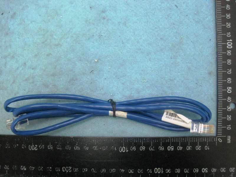
Click to zoom
Application Details
- Equipment Class
- DTS - Digital Transmission System
- Date of Grant
- May 22, 2014
- Application Purpose
- Original Equipment
- Date of Application
- Feb 24, 2014
- Equipment Note
- Wireless-AC/N Dual Radio AP with Single Point Setup
- Frequency Range
- 5775.00000000 - 5775.00000000
- Company
- CyberTAN Technology Inc.
- Country
- Taiwan
Documents & Files
Document Text
Text extracted from the exhibit documents filed with the FCC. Open a document above to read the original.
Users Manual
Quick Start Guide Guide de démarrage rapide 快速入门指南 Cisco Small Business 371 Series Wireless Access Point Point d'accès sans fil Série 371 371 系列无线接入点 2Cisco Small Business WAP371 Series Wireless Access Point Welcome Thank you for choosing the Cisco Small Business WAP371 Wireless Access Point. The Cisco WAP371 is an indoor dual radio 802.11ac + 802.11n access point. This guide is designed to familiarize you with the general layout of the access point, describe how to deploy the device in your network, and describe how to configure the device. Your access point has more features and functionality than what is described in this guide. For additional information, see the Administration Guide. A link to the Administration Guide is found in “Where to Go From Here” on page 11. Package Contents • Wireless Access Point • Mounting kit • This Quick Start Guide • Product CD • Ethernet cable Before You Begin Before you begin the installation, make sure that you have the following equipment and services: • A computer with browser support for: –Internet Explorer v7.0 or later –Chrome v5.0 or later –Firefox v3.0 or later –Safari v3.0 or later • Tools for installing the hardware • One or more Ethernet network switches with PoE Cisco WAP371 Wireless-AC/N Dual Radio Access Point with Single Point Setup Features Front Panel The front panel of the device consists of three lights: Power, WLAN, and LAN. For full descriptions of the colors of the lights and their indications, see “Verifying the Hardware Installation”. 1 2 Cisco Small Business WAP371 Series Wireless Access Point3 A Kensington lock slot is found under the lights. Back Panel The back panel of the device has an RJ-45 Ethernet port. Use the Ethernet port to power your device using PoE. It is an auto-sensing, Gigabit Ethernet (802.3) port used to connect your WAP devices to network devices, such as computers, routers, or switches. We strongly recommend that you use a Category 5e or better cable for gigabit connectivity. The back panel of the device has a Reset button. See “Rebooting the Devices or Returning them to their Factory Default Settings” for information on the Reset button. Default Settings If you are using a Cisco Small Business RV Series router, the default range for the DHCP assigned address is from 192.168.1.100 to 192.168.1.254. Any device connecting to the same LAN will be assigned an IP address in this range. ParameterDefault Value Usernamecisco Passwordcisco LAN IP AddressDHCP address assigned by server Fallback LAN IP192.168.1.245 Subnetwork Mask255.255.255.0 4Cisco Small Business WAP371 Series Wireless Access Point Mounting the Cisco WAP371 Wireless-AC/N Dual Radio Access Point with Single Point Setup You can place your access point on a desktop, or mount it on a wall or ceiling. Placement Tips • Ambient Temperature—To prevent the access point from overheating, do not operate it in an area that exceeds an ambient temperature of 104°F (40°C). • Air Flow—Both side panels have vents that must be unobstructed to prevent overheating. • Mechanical Loading—The device should be level, stable, and secure to prevent it from sliding or shifting out of position. Wall and Ceiling Mounting The Cisco WAP371 device can be wall or ceiling-mounted. A mounting kit is packaged with your device. The kit is designed to install your device to the wall or the ceiling. The mounting bracket has some flexibility so that you can reuse existing holes drilled for a Cisco WAP551 or WAP561 device. The installer can remove the Cisco WAP551 or WAP561 and mount the Cisco WAP371. The dimensions for the mount kit screws are as follows: WARNINGInsecure mounting might damage the device or cause injury. Cisco is not responsible for damages incurred by insecure wall or ceiling mounting. 1.31 to .33 in (7.8 to 8.3 mm) 2.86 to .88 in (21.8 to 22.3 mm) 3.22 to .24 in (5.5 to 6.0 mm) 4.69 to .72 in (17.5 to 18.2 mm) 3 1 2 4 3 196243 Cisco Small Business WAP371 Series Wireless Access Point5 To mount the Cisco WAP 371 device to a wall or ceiling: STEP1Determine where you want to mount the device. Verify that the surface is smooth, flat, dry, and sturdy. STEP2Drill two pilot holes into the surface 2.75 inches (70 mm) apart for your Cisco WAP device. STEP3Insert a screw into each hole, leaving a gap between the surface and the base of the screw head. STEP4Place the upper slots of the bracket over the screws, adjust the screws accordingly, and slide the bracket down until the screws fit snugly into the slots. STEP5Using the bracket as a template, drill two more holes for the lower screws. STEP6Insert a screw into each lower hole. STEP7Slide the WAP device into the bracket, placing the cable through the break- out tab found in the back of the bracket. Connecting the Cisco WAP371 Wireless-AC/N Dual Radio Access Point with Single Point Setup The default configuration of the device has the Wi-Fi radio turned off. You must perform the initial configuration using a wired Ethernet connection. To connect the device to the wired network: STEP1Connect the Ethernet cable to the Ethernet port of a switch, a router, or a PC. STEP2Connect the other end of the network Ethernet cable to the Ethernet port of the wireless access point. After installation, all lights should be active. Refer to Verifying the Hardware Installation, page 6 for details about the different lights on each switch. 4 6Cisco Small Business WAP371 Series Wireless Access Point Verifying the Hardware Installation To verify the hardware installation, complete the following tasks: • Check the cable connections. • Check the state of the indicator lights. NOTEIf you need help resolving a problem, visit the Cisco Small Business Support Community at www.cisco.com/go/smallbizsupport. LabelActivityDescription Power OffThe device has no power. Solid GreenThe device is powered on. Normal operation. Flashing GreenUpgrading firmware or acquiring an IPv4 address. Solid RedBooting or firmware upgrade failed. WLAN OffWireless is disabled, for…
Text truncated - open the document above for the full version.
Cover Letter(s)
Page No. : 3 CyberTAN Technology, Inc. No. 99, Park Avenue III, Science-based Industrial Park, Hsinchu, 308 Taiwan Tel: 886-3-5777777 / Fax: 886-3- 5635191 Confidential Letter Date: 2014/2/13 Federal Communications Commission Authorization and Evaluation Division FCC ID:N89-WAP371 Confidentiality Request Pursuant to Sections 0.457 and 0.459 of the Commission’s Rules, the Applicant Hereby requests confidential treatment of information accomparting this Application As outlined below: 1. Block Diagram 2. Circuit Diagram 3. Operational Description The above materials contain trade secrets and proprietary information not customarily released to the public. The public disclosure of these matters might be harmful to the Applicant and provide unjustified benefits to its competitors. The Applicant understands that pursuant to Rule 0.457, disclosure of this Application and all accompanying documentation will not be made before the date of the Grant for this application Sincerely, Applicant’s company name : CyberTAN Technology, Inc. Applicant’s company address : No. 99, Park Avenue III, Science-based Industrial Park, Hsinchu, 308 Taiwan Signature : Name and Job Title : Amy Wu / Manager E-Mail : [email protected] Tel. : 886-3-5777777
Cover Letter(s)
Page No. : 4 CyberTAN Technology, Inc. No. 99, Park Avenue III, Science-based Industrial Park, Hsinchu, 308 Taiwan Tel: 886-3-5777777 / Fax: 886-3- 5635191 DoC Attestation Letter Date: 2014/2/13 We CyberTAN Technology, Inc., as the grantee of this project (FCC ID: N89-WAP371 / Brand Name: Cisco / Model No.: WAP371), would like to declare that the composite portion categorized as computer peripheral has been authorized under the Declaration of Conformity procedures (Sproton report No.: FD3O0832, FCC Test Firm Registration No.: 187376). The final product shall consequently comply with the FCC rule applied for DoC Procedure. Regards, FCC Grantee contact person information. Applicant’s company name : CyberTAN Technology, Inc. Applicant’s company address : No. 99, Park Avenue III, Science-based Industrial Park, Hsinchu, 308 Taiwan Signature : Name and Job Title : Amy Wu / Manager E-Mail : [email protected] Tel. : 886-3-5777777
Cover Letter(s)
Page No. : 2 CyberTAN Technology, Inc. No. 99, Park Avenue III, Science-based Industrial Park, Hsinchu, 308 Taiwan Tel: 886-3-5777777 / Fax: 886-3- 5635191 Power of Attorney Date: 2014/2/13 Dear Sir, I hereby have entrusted the following person to be a proxy regarding application for Type Certification. Sporton International Inc. Address : No.8, Lane 724, Bo-ai St., Jhubei City, HsinChu County 302, Taiwan, R.O.C. Name : Leo Huang Job Title : Manager e-mail : [email protected] I am therefore responsible for the contents of the application. Brand name and model type of the specified radio equipment: Cisco / WAP371 FCC ID: N89-WAP371 Product name: Wireless-AC/N Dual Radio Point with Single Point Setup FCC Grantee contact person information. Applicant’s company name : CyberTAN Technology, Inc. Applicant’s company address : No. 99, Park Avenue III, Science-based Industrial Park, Hsinchu, 308 Taiwan Signature : Name and Job Title : Amy Wu / Manager E-Mail : [email protected] Tel. : 886-3-5777777
Cover Letter(s)
Page No. : 6 CyberTAN Technology, Inc. No. 99, Park Avenue III, Science-based Industrial Park, Hsinchu, 308 Taiwan Tel: 886-3-5777777 / Fax: 886-3- 5635191 Restricted band Declaration Letter Date: 2014/2/13 FCC ID:N89-WAP371 We, the undersigned, attest that this device does not support operation in the 5600 - 5650 MHz Band. The firmware on the device restricts the operation in this frequency band and does not utilize the channels in this band. FCC Grantee contact person information. Applicant’s company name : CyberTAN Technology, Inc. Applicant’s company address : No. 99, Park Avenue III, Science-based Industrial Park, Hsinchu, 308 Taiwan Signature : Name and Job Title : Amy Wu / Manager E-Mail : [email protected] Tel. : 886-3-5777777
Cover Letter(s)
Page No. : 5 CyberTAN Technology, Inc. No. 99, Park Avenue III, Science-based Industrial Park, Hsinchu, 308 Taiwan Tel: 886-3-5777777 / Fax: 886-3- 5635191 Uniform spreading & TPC Declaration Letter Date: 2014/2/13 FCC ID:N89-WAP371 To Whom it may concern, Uniform Spreading Statement: We, CyberTAN Technology, Inc., declare that the EUT (Model Name: WAP371). Uniform Spreading is required across the frequency ranges 5250 MHz to 5350 MHz and 5470 MHz to 5725 MHz. Channel plans (5250 MHz to 5350 MHz and 5470 MHz to 5725 MHz) shall make use of 60 % of the spectrum available in the applicable sub-band(s). Each of the Usable Channels will be used with approximately equal probability. RLAN band 5600 MHz to 5650 MHz omit these channels from the list of Usable Channels at initial power up or at initial installation. In the other way, the software and associated drivers to support TPC are built into the device firmware. Regards, FCC Grantee contact person information. Applicant’s company name : CyberTAN Technology, Inc. Applicant’s company address : No. 99, Park Avenue III, Science-based Industrial Park, Hsinchu, 308 Taiwan Signature : Name and Job Title : Amy Wu / Manager E-Mail : [email protected] Tel. : 886-3-5777777
External Photos
Report No.:3O0832 SPORTON International Inc. PAGE NUMBER : 1 OF 4 TEL : 886-3-327-3456 ISSUED DATE : Feb. 25, 2014 FAX : 886-3-327-0973 Photographs of EUT Report No.:3O0832 SPORTON International Inc. PAGE NUMBER : 2 OF 4 TEL : 886-3-327-3456 ISSUED DATE : Feb. 25, 2014 FAX : 886-3-327-0973 Report No.:3O0832 SPORTON International Inc. PAGE NUMBER : 3 OF 4 TEL : 886-3-327-3456 ISSUED DATE : Feb. 25, 2014 FAX : 886-3-327-0973 RJ-45 cable Report No.:3O0832 SPORTON International Inc. PAGE NUMBER : 4 OF 4 TEL : 886-3-327-3456 ISSUED DATE : Feb. 25, 2014 FAX : 886-3-327-0973 Cradle
ID Label/Location Info
Label Size: 60*78mm
Internal Photos
Report No.:3O0832 SPORTON International Inc. PAGE NUMBER : 1 OF 3 TEL : 886-3-327-3456 ISSUED DATE : Feb. 25, 2014 FAX : 886-3-327-0973 Photographs of EUT Report No.:3O0832 SPORTON International Inc. PAGE NUMBER : 2 OF 3 TEL : 886-3-327-3456 ISSUED DATE : Feb. 25, 2014 FAX : 886-3-327-0973 Report No.:3O0832 SPORTON International Inc. PAGE NUMBER : 3 OF 3 TEL : 886-3-327-3456 ISSUED DATE : Feb. 25, 2014 FAX : 886-3-327-0973
RF Exposure Info
Report No.: FR3O0832 FCC ID: N89-WAP371 Page No. : B1 of B3 Appendix B. Maximum Permissible Exposure Report No.: FR3O0832 FCC ID: N89-WAP371 Page No. : B2 of B3 1. Maximum Permissible Exposure 1.1. Applicable Standard Systems operating under the provisions of this section shall be operated in a manner that ensures that the public is not exposed to radio frequency energy levels in excess limit for maximum permissible exposure. In accordance with 47 CFR FCC Part 2 Subpart J, section 2.1091 this device has been defined as a mobile device whereby a distance of 0.2 m normally can be maintained between the user and the device. (A) Limits for Occupational / Controlled Exposure Frequency Range (MHz) Electric Field Strength (E) (V/m) Magnetic Field Strength (H) (A/m) Power Density (S) (mW/ cm²) Averaging Time |E|²,|H|² or S (minutes) 0.3-3.0 614 1.63 (100)* 6 3.0-30 1842 / f 4.89 / f (900 / f)* 6 30-300 61.4 0.163 1.0 6 300-1500 F/300 6 1500-100,000 5 6 (B) Limits for General Population / Uncontrolled Exposure Frequency Range (MHz) Electric Field Strength (E) (V/m) Magnetic Field Strength (H) (A/m) Power Density (S) (mW/ cm²) Averaging Time |E|²,|H|² or S (minutes) 0.3-1.34 614 1.63 (100)* 30 1.34-30 824/f 2.19/f (180/f)* 30 30-300 27.5 0.073 0.2 30 300-1500 F/1500 30 1500-100,000 1.0 30 Note: f = frequency in MHz ; *Plane-wave equivalent power density 1.2. MPE Calculation Method E (V/m) = d GP30 Power Density: Pd (W/m²) = 377 2 E E = Electric field (V/m) P = Average RF output power (W) G = EUT Antenna numeric gain (numeric) d = Separation distance between radiator and human body (m) The formula can be changed to Pd = 2 377 30 d GP From the EUT RF output power, the minimum mobile separation distance, d=0.2m, as well as the gain of the used antenna, the RF power density can be obtained. Report No.: FR3O0832 FCC ID: N89-WAP371 Page No. : B3 of B3 1.3. Calculated Result and Limit For 5GHz UNII Band: Antenna Type : PIFA Antenna Max Conducted Power for IEEE 802.11ac VHT40 : 23.86 dBm Antenna Gain (dBi) Antenna Gain (numeric) Average Output Power (dBm) Average Output Power (mW) Power Density (S) (mW/cm²) Limit of Power Density (S) (mW/cm²) Test Result 5.39 3.4594 23.8622 243.3456 0.167561 1 Complies For 5GHz ISM Band: Antenna Type : PIFA Antenna Max Conducted Power for IEEE 802.11a: 28.23 dBm Antenna Gain (dBi) Antenna Gain (numeric) Average Output Power (dBm) Average Output Power (mW) Power Density (S) (mW/cm²) Limit of Power Density (S) (mW/cm²) Test Result 5.39 3.4594 28.2317 665.5318 0.458268 1 Complies For 2.4GHz Band: Antenna Type : PIFA Antenna Max Conducted Power for IEEE 802.11g: 23.06 dBm Antenna Gain (dBi) Antenna Gain (numeric) Average Output Power (dBm) Average Output Power (mW) Power Density (S) (mW/cm²) Limit of Power Density (S) (mW/cm²) Test Result 3.15 2.0654 23.0553 202.0843 0.083077 1 Complies CONCULSION: Both of the WLAN 2.4GHz Band and WLAN 5GHz Band can transmit simultaneously, the formula of calculatedthe MPE is: CPD1 / LPD1 + CPD2 / LPD2 + ......etc. < 1 CPD = Calculation power density LPD = Limit of power density Therefore, the worst-case situation is 0.083077 / 1 + 0.458268 / 1 = 0.541345, which is less than “1”. This confirmed that the device comply with FCC 1.1310 MPE limit.
Test Report
SPORTON International Inc. No. 52, Hwa Ya 1st Rd., Hwa Ya Technology Park, Kwei-Shan Hsiang, Tao Yuan Hsien, Taiwan, R.O.C. Ph: 886-3-327-3456 / FAX: 886-3-327-0973 / www.sporton.com.tw Report Format Version: 01 FCC RADIO TEST REPORT Applicant’s company CyberTAN Technology, Inc. Applicant Address No. 99, Park Avenue III, Science-based Industrial Park, Hsinchu, 308 Taiwan FCC ID N89-WAP371 Manufacturer’s company CyberTAN Technology, Inc. Manufacturer Address No. 99, Park Avenue III, Science-based Industrial Park, Hsinchu, 308 Taiwan Product Name Wireless-AC/N Dual Radio Point with Single Point Setup Brand Name Cisco Model No. WAP371 Test Rule Part(s) 47 CFR FCC Part 15 Subpart C § 15.247 Test Freq. Range 2400 ~ 2483.5MHz / 5725 ~ 5850MHz Received Date Oct. 08, 2013 Final Test Date Jan. 28, 2014 Submission Type Original Equipment Statement Test result included is only for the IEEE 802.11n, IEEE 802.11b/g part and IEEE 802.11a/ac (5725 ~ 5850MHz) of the product. The test result in this report refers exclusively to the presented test model / sample. Without written approval of SPORTON International Inc., the test report shall not be reproduced except in full. The measurements and test results shown in this test report were made in accordance with the procedures and found in compliance with the limit given in ANSI C63.10-2009, 47 CFR FCC Part 15 Subpart C, KDB 558074 D01 v03r01, KDB 662911 D01 v02r01 and KDB644545 D01v01r02. The test equipment used to perform the test is calibrated and traceable to NML/ROC. Report No.: FR3O0832AA Report Format Version: 01 Page No. : i of ii FCC ID: N89-WAP371 Issued Date : Feb. 25, 2014 Table of Contents 1. CERTIFICATE OF COMPLIANCE ......................................................................................................................... 1 2. SUMMARY OF THE TEST RESULT .......................................................................................................................... 2 3. GENERAL INFORMATION .................................................................................................................................. 3 3.1. Product Details....................................................................................................................................................................................3 3.2. Accessories .........................................................................................................................................................................................5 3.3. Table for Filed Antenna.......................................................................................................................................................................6 3.4. Table for Carrier Frequencies .............................................................................................................................................................7 3.5. Table for Test Modes ...........................................................................................................................................................................8 3.6. Table for Testing Locations................................................................................................................................................................10 3.7. Table for Supporting Units .................................................................................................................................................................11 3.8. Table for Parameters of Test Software Setting ...................................................................................................................................12 3.9. EUT Operation during Test .................................................................................................................................................................13 3.10. Duty Cycle ........................................................................................................................................................................................14 3.11. Test Configurations ...........................................................................................................................................................................18 4. TEST RESULT ................................................................................................................................................... 21 4.1. AC Power Line Conducted Emissions Measurement.........................................................................................................................21 4.2. Maximum Conducted Output Power Measurement .........................................................................................................................25 4.3. Power Spectral Density Measurement ..............................................................................................................................................28 4.4. 6dB Spectrum Bandwidth Measurement ..........................................................................................................................................42 4.5. Radiated Emissions Measurement ....................................................................................................................................................51 4.6. Emissions Measurement ....................................................................................................................................................................79 4.7. Antenna Requirements ...................................................................................................................................................................108 5. LIST OF MEASURING EQUIPMENTS ................................................................................................................. 109 6. MEASUREMENT UNCERTAINTY............................................................................…
Text truncated - open the document above for the full version.
Test Report
Report No.: FR3O0832 FCC ID: N89-WAP371 Page No. : C1 of C3 Appendix C. Radiated Emission Co-location Report Report No.: FR3O0832 FCC ID: N89-WAP371 Page No. : C2 of C3 1. Results of Radiated Emissions for Co-located Temperature 25°C Humidity 62% Test Engineer David Tseng Configurations 2.4G + 5G Test Mode Mode 3 Horizontal Report No.: FR3O0832 FCC ID: N89-WAP371 Page No. : C3 of C3 Vertial
Test Setup Photos
Report No.: FR3O0832 FCC ID: N89-WAP371 Page No. : A1 of A5 Appendix A. Test Photos Report No.: FR3O0832 FCC ID: N89-WAP371 Page No. : A2 of A5 1. Photographs of Conducted Emissions Test Configuration Test Mode: Mode 1 FRONT VIEW REAR VIEW Report No.: FR3O0832 FCC ID: N89-WAP371 Page No. : A3 of A5 2. Photographs of Radiated Emissions Test Configuration Test Configuration: 9kHz ~30MHz / Test Mode: Mode 3 FRONT VIEW REAR VIEW Report No.: FR3O0832 FCC ID: N89-WAP371 Page No. : A4 of A5 Test Configuration: 30MHz~1GHz / Test Mode: Mode 3 FRONT VIEW REAR VIEW Report No.: FR3O0832 FCC ID: N89-WAP371 Page No. : A5 of A5 Test Configuration: Above 1GHz / Test Mode: Mode 3 FRONT VIEW REAR VIEW
Test Setup Photos
Report No.: FZ3O0832 FCC ID: N89-WAP371 Page No. : A1 of A2 Appendix A. Test Photos Report No.: FZ3O0832 FCC ID: N89-WAP371 Page No. : A2 of A2 1. Photographs of Dynamic Frequency Selection Test Configuration FRONT VIEW
Contact Information
Applicant
City Kuo(Director)
Technical Contact
Sporton International Inc.Sharon Jiang
[email protected]886-3-656-9065
No.8, Lane 724, Bo-ai St., Jhubei City, · Hsinchu County · Taiwan
Non-Technical Contact
Sporton International Inc.Sharon Jiang
[email protected]886-3-656-9065
Test Firm
Sporton International Inc.Alex Chen
Technical Specifications
| # | Rule Parts | Frequency Range | Power Output |
|---|---|---|---|
| 5 | 15C | 5.78 GHz - 5.78 GHz | 217.80 mW |
Other Applications from CyberTAN Technology Inc.

N89-RAP750EV1
Jan 02, 2026BE5000 Wireless Dual Band Outdoor Wall Mount Access Point
Equipment Class
NII - Unlicensed National Information Infrastructure TXN89-711C341XV1
Sep 09, 2024BE11000 Wireless Tri Band Ceiling Mount Access Point
Equipment Class
DTS - Digital Transmission System
N89-EWW631C1V1
Feb 15, 2024AX3000 Wireless Dual Band Wall Mount Access Point
Equipment Class
DTS - Digital Transmission System
N89-DPC3848VE
Aug 31, 2015DOCSIS 3.0 24x8 Wireless Residential Gateway
Equipment Class
NII - Unlicensed National Information Infrastructure TX
N89-RM5110
Jun 23, 2015ViaSat Residential Broadband Gateway
Equipment Class
DTS - Digital Transmission System