N96120332ISMPFELECTRONIC BALLAST
Sunpark Electronics Corp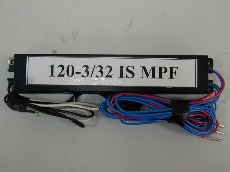
Click to zoom
Application Details
- Equipment Class
- 8CC - Part 18 Consumer Device
- Date of Grant
- Jun 05, 2006
- Application Purpose
- Original Equipment
- Date of Application
- Jun 05, 2006
- Equipment Note
- ELECTRONIC BALLAST
- Frequency Range
- 0.02600000 - 0.02600000
- Company
- Sunpark Electronics Corp
- Country
- United States
Documents & Files
Document Text
Text extracted from the exhibit documents filed with the FCC. Open a document above to read the original.
Users Manual
ELECTRONIC BALLAST INSTALLATION INSTRUCTION S UNPARK ELECTRONICS CORP. Model : 120-3/32IS MPF CAUTIONARY NOTES: Do not use this equipment for other than intended use. 1. Verify that the line voltage matches the ballast voltage. 2. Installation to be made by a qualified person in accordance with applicable codes. Warning This product may cause interference to radio equipment and should not be installed near maritime safety communications equipment or other critical navigation or communication equipment operating between 0.45-30 MHz. Features z 120V AC input z Mid Power Factor z Class P z Sound rating A z UL, cUL recognized. File E177888 z Indoor / outdoor use. Lamp type & power consumption : Lamp Input Power T8 32W x 3 85W T8 25W x 3 65W T8 18W x 3 48W T8 17W x 3 46W T8 15W x 3 38W T12 40W x 3 72W T12 34W x 3 60W T12 25W x 3 67W Before installation 1. Disconnect line voltage before installing or replacing lamp. 2. Ballast case must be grounded. 3. Place the ballast to a stable support and fix it. Installation 1. Connect the lamps to the ballast according to the label . Ballast supports only the type of lamps specified on the product label. 2. Connect the AC power line. Connect the black wire to L terminal and white wire to N terminal of the AC source. 3. Connections of power wires must be fully insulated.
Block Diagram
1 2 3 4 56 ABCD 6 5 4 3 2 1 D CBA Line Filter Rectifier Driver Lamps Sunpark Electronics Corp. Output Transformer Block diagram Grantee Code: N96FCC ID: N96120332ISMPFModel No.: 120-3/32IS MPF LineInput
External Photos
Project No.: 0605040 Page 2 of 5 Neutron Engineering Inc. 0605040 0605040 Project No.: 0605040 Page 3 of 5 Neutron Engineering Inc. 0605040 0605040
ID Label/Location Info
Report No.: NEI-FCCE-1-0605040 Page 19 of 19 Neutron Engineering Inc. 6. PRODUCT LABELING -- FCC ID label -- The remained portion of label statement required by FCC is attached in the user’s manual. -- Location of Label on EUT -- 0.4 cm 3.2 cm
Internal Photos
Project No.: 0605040 Page 4 of 5 Neutron Engineering Inc. 0605040 0605040 Project No.: 0605040 Page 5 of 5 Neutron Engineering Inc. 0605040 0605040
Operational Description
Product Description ISM Equipment Category: Consumer Equipment Open Circuit Voltage: 600V Nominal Operating Frequency: 26 KHz Based on the application, features, or specification exhibited in User's Manual, the EUT is considered as a consumer ISM equipment (RF lighting device). More details of EUT technical specification, please refer to the User's Manual.
Schematics
1 2 3 4 56 ABCD 6 5 4 3 2 1 D CBA Revision : Date : Drawn by : Sheet of Name : 120-3/32IS MPF + C2 L3 F1 C5 BLK WHT GRD C9B VR1 D5D7 D6 R2 R3 C6 C8 C7 D12 R1 D11 T4 D8 R4 T2 R5 C10A Q1Q2 1S 1F 2F 2S 1 Y1 1 2B C10BC10C 1 2B 1 2B LionfoxZeng C3C4 C9A C1 VCC L5A L5B 1 2 3 4 DB1 R1
Test Report
Report No.: NEI-FCCE-1-0605040 Page 2 of 19 Neutron Engineering Inc. Declaration Neutron represents to the client that testing is done in accordance with standard procedures as applicable and that test instruments used has been calibrated with the standards traceable to National Measurement Laboratory (NML) of R.O.C., or National Institute of Standards and Technology (NIST) of U.S.A. Neutron's reports apply only to the specific samples tested under conditions. It is manufacture’s responsibility to ensure that additional production units of this model are manufactured with the identical electrical and mechanical components. Neutronshall have no liability for any declarations, inferences o r generalizations drawn by the client or others from Neutron issued reports. Neutron’s reports must not be used by the client to claim product endorsement by the authorities or any agency of the Government. This report is the confidential property of the client. As a mutual protection to the clients, the public and Neutron-self, extracts from the test report shall not be reproduced except in full with Neutron’s authorized written approval. Neutron’s laboratory quality assurance procedures are in compliance with the ISO Guide 17025 requirements, and accredited by the conformity assessment authorities listed in this test report. Limitation For the use of the authority's logo is limited unless the Test Standard(s)/Scope(s)/Item(s) mentioned in this test report is (are) included in the conformity assessment authorities acceptance respective. Report No.: NEI-FCCE-1-0605040 Page 3 of 19 Neutron Engineering Inc. Table of Contents Page 1 . CERTIFICATION 4 2 . SUMMARY OF TEST RESULTS 5 2.1 TEST FACILITY 6 2.2 MEASUREMENT UNCERTAINTY 6 3 . GENERAL INFORMATION 7 3.1 GENERAL DESCRIPTION OF EUT 7 3.2 DESCRIPTION OF TEST MODES 8 3.3 BLOCK DIGRAM SHOWING THE CONFIGURATION OF SYSTEM TESTED 9 3.4 DESCRIPTION OF SUPPORT UNITS 10 4 . RFI EMC EMISSION TEST 11 4.1 CONDUCTED EMISSION MEASUREMENT 11 4.1.1 POWER LINE CONDUCTED EMISSION LIMITS 11 4.1.2 MEASUREMENT INSTRUMENTS LIST 11 4.1.3 TEST PROCEDURE 12 4.1.4 DEVIATION FROM TEST STANDARD 12 4.1.5 TEST SETUP 12 4.1.6 EUT OPERATING CONDITIONS 12 4.1.7 TEST RESULTS 13 5 . EUT TEST PHOTO 17 6 . PRODUCT LABELING 19 Report No.: NEI-FCCE-1-0605040 Page 4 of 19 Neutron Engineering Inc. 1. CERTIFICATION E q u i p m e n t : ELECTRONIC BALLAST Trade Name : SUNPARK M o d e l N o . : 120-3/32IS MPF A p p l i c a n t : SUNPARK ELECTRONICS CORP. Data of Test : May 10, 2006 ~ May 23, 2006 Te s t I t e m : ENGINEERING SAMPLE Standards : FCC Part 18 , Section 18.305(C) and 18.307(C) , Consumer Equipment Limits The above equipment has been tested and found compliance with the requirement of the relative standards by Neutron Engineering Inc. EMC Laboratory. The test data, data evaluation, and equipment configuration contained in our test report (Ref No. NEI-FCCE-1-0605040) were obtained utilizing the test procedures, test instruments, test sites that has been accredited by the Authority of NVLAP and CNLA according to the ISO-17025 quality assessment standard and technical standard(s). Report No.: NEI-FCCE-1-0605040 Page 5 of 19 Neutron Engineering Inc. 2. SUMMARY OF TEST RESULTS Test procedures according to the technical standards: FCC Part18, Subpart C Standard Section Test Item Judgment Remark 18.307(C) Conducted Emission PASS Consumer Equipment NOTE: (1)” N/A” denotes test is not applicable in this Test Report Report No.: NEI-FCCE-1-0605040 Page 6 of 19 Neutron Engineering Inc. 2.1 TEST FACILITY The test facilities used to collect the test data in this report is C01 at the location of No.132-1, Lane 329, Sec. 2, Palain Road, Shijr City, Taipei, Taiwan. A description of this test facilities is already on file with the FCC as registration number of 95335. 2.2 MEASUREMENT UNCERTAINTY The reported uncertainty of measurement y ± U,where expended uncertainty U is based on a standard uncertainty multiplied by a coverage factor of k=2,providing a level of confidence of approximately 95 %。 A. Conducted Measurement : Test Site Method Measurement Frequency Range U,(dB) NOTE C01 ANSI150 KHz ~ 30MHz 1.94 B. Radiated Measurement : Test Site Method Measurement Frequency Range Ant. H / V U,(dB) NOTE OS-01 ANSI30MHz ~ 200MHz V 3.82 30MHz ~ 200MHz H 3.60 200MHz ~ 1,000MHz V 3.86 200MHz ~ 1,000MHz H 3.94 OS-02 ANSI30MHz ~ 200MHz V 2.48 30MHz ~ 200MHz H 2.16 200MHz ~ 1,000MHz V 2.50 200MHz ~ 1,000MHz H 2.66 Report No.: NEI-FCCE-1-0605040 Page 7 of 19 Neutron Engineering Inc. 3. GENERAL INFORMATION 3.1 GENERAL DESCRIPTION OF EUT Equipment ELECTRONIC BALLAST Trade Name SUNPARK Model No. 120-3/32IS MPF Product Description ISM Equipment Category: Consumer Equipment Open Circuit Voltage: 600V Nominal Operating Frequency: 26 KHz Based on the application, features, or specification exhibited in User's Manual, the EUT is considered as a consumer ISM equipment (RF lighting device). More details of EUT technical specification, please refer to the User's Manual. Power Supply AC I/P 120V, 60Hz, 1.23A Connecting I/O Port(s) Please refer to the User's Manual Note: 1. For a more detailed features description, please refer to the manufacturer’s specifications or the User's Manual. Report No.: NEI-FCCE-1-0605040 Page 8 of 19 Neutron Engineering Inc. 3.2 DESCRIPTION OF TEST MODES To investigate the maximum EMI emission characteristics generates from EUT, the test system was pre-scanning tested base on the consideration of following EUT operation mode or test configuration mode which possible have effect on EMI emission level. Each of these EUT operation mode(s) or test configuration mode(s) mentioned above was evaluated respectively. Pretest Test ModeDescription Mode 1 T8 32W x 3 / 85W Mode 2 T8 25W x 3 / 65W Mode 3 T8 18W x 3 / 48W Mode 4 T8 17W x 3 / 46W Mode 5 T8 15W x 3 / 38W Mode 6 T12 40W x 3 / 72W Mode 7 T12 34W x 3 / 60W Mode 8 T12 25W x 3 / 67W For Conducted / Radiated Test Final Test Mode Description Mode 1 T8 32W x 3 …
Text truncated - open the document above for the full version.
Test Setup Photos
Report No.: NEI-FCCE-1-0605040 Page 17 of 19 Neutron Engineering Inc. 5. EUT TEST PHOTO Conducted Measurement Photos T8 32W x 3 / 85W Report No.: NEI-FCCE-1-0605040 Page 18 of 19 Neutron Engineering Inc. Conducted Measurement Photos T8 17W x 3 / 46W
Contact Information
Applicant
Meynardo J. Velasco(Chief Operating Officer)
Test Firm
BTL Inc.Andy Yeh
Technical Specifications
| # | Rule Parts | Frequency Range | Power Output |
|---|---|---|---|
| 1 | 18 | 0.026 MHz - 0.026 MHz | - |
Other Applications from Sunpark Electronics Corp
N9644000104
Aug 25, 2003Electronic Ballast
Equipment Class
8CC - Part 18 Consumer Device
N96-120332IS
Aug 12, 2003Electronic Ballast
Equipment Class
8CC - Part 18 Consumer Device
N96-120232IS
Jul 29, 2003ELECTRONIC BALLAST
Equipment Class
8CC - Part 18 Consumer Device
N96-U1-2HOUVW
Jul 06, 2003Electronic Ballast
Equipment Class
8CC - Part 18 Consumer Device
N96U1-2HOUVW
Jun 26, 2003ELECTRONIC BALLAST
Equipment Class
8CC - Part 18 Consumer Device