N9Z-NU-701Wireless Food Thermometer Transmitter
Ewig Industries Macao Commercial Offshore Limited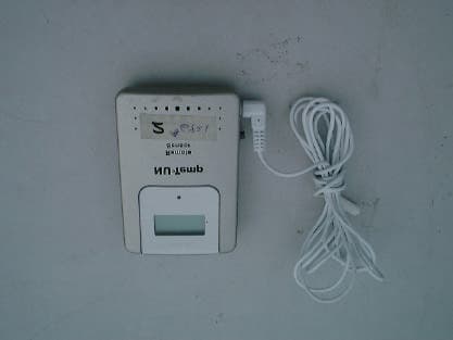
Click to zoom
Application Details
- Equipment Class
- DSC - Part 15 Security/Remote Control Transmitter
- Date of Grant
- Nov 04, 2001
- Application Purpose
- Original Equipment
- Date of Application
- Nov 04, 2001
- Equipment Note
- Wireless Food Thermometer Transmitter
- Frequency Range
- 433.90000000 - 433.90000000
- Country
- Macau
Documents & Files
Document Text
Text extracted from the exhibit documents filed with the FCC. Open a document above to read the original.
Users Manual
Simple Wireless Food/Meat Thermometer User Guide Simple Two Step Setup Simple Set up Instructions Remote Sensor: 1. Remove the stand clip from the four comers on back of unit. 2. Insert 3 AAA Alkaline or Lithium batteries in remote sensor by removing the four screws on back of unit. (The stand clip must be removed) 3. LCD display will show all segments of 3 seconds 4. Attach sensor if required for application 5. Sensor will automatically link to Main Station when Main Station is activated. 6. Press the C/F button toggle between Centigrade and Fahrenheit. Simple Set up Instructions Main Station: 1. Insert two AAA Alkaline or Lithium batteries in main station in battery compartments. 2. LCD display will show all segments for 3 seconds and keeps and goes into to receiving mad for 1 minute. 3. Main Station automatically links remote transmitters. Write the sensor number on back of remote sensor to include which channel is being used for a particular sensor. Specifications:Operating Instructions Main Station: Temperature Range –40F to 392F (40°C to 200°C) LLL indicates reading less than –40F (40°C) HHH indicates reading more than 392F (200°C) Display resolution 1 degree C/F Indoor temperature Temperature range 32F to 122F (0°C - 122°C) LLL indicates reading less than 32F (0°C) HHH indicates reading higher than 122F (50°C) 1. Normal operation – The Main Station automatically links up to three remote transmitters. If more than one sensor is being used the next higher channel is automatically selected. If all three channels are in use, the main station will automatically replace Channel 1. 2. C/F button – on back of unit is used to toggle between Centigrade and Fahrenheit. 3. Hi/Low Button – Pressing the Hi/Low button on back will toggle between higher than and lower than temperature set points. This is indicated by arrows on the LCD screen. 4. Channel Button – on back will change channel display when multiple sensors are used. A Channel Auto scroll feature in enabled by holding the Channel button down for 2 seconds. The remote temperature display will then display each remote sensor for 2 seconds. 5. Hi/Low Button & Channel Button – When pressed together it allows toggling between indoor temperature display or set temperature display. 6. Set Button – on front is used to set remote temperature alarms. Depressing the set button will allow a toggle between channels when multiple sensors are in use. 7. Up arrow – pressing the up arrow on front is used in set mode and will increases the set temperature 1 degree per second. 8. Alarm Set Point Reached – When more than one remote alarm set point is reached the left most display will be overwritten with the temperature with the remote sensor temperature that has reached its set point. 9. Alarm – The Alarm will sound when the set temperature is reached until. Battery Life – 5 months depending on use Low Battery indicators – if remote sensor batteries or main station batteries are low an icon will be present on main station. Caution: Do not mix alkaline batteries with Cadmium or Lithium batteries. Note: The temperature displayed is taken from the interior sensor unless probe is used. When the probe is used the temperature display is form the probe itself. FCC Statement: This device complies with part 15 of the FCC Rules. Operation is subject to the following two conditions: (1) This device may not cause harmful interference, and (2) this device must accept any interference received, including interference that may cause undesired operation. A. Any front key is pressed (Set or Up arrow) B. The Alarm Times Out after 1 minute NOTE: This equipment has been tested and found to comply with the limits for a Class B digital device, pursuant to Part 15 of the FCC Rules. These limits are designed to provide reasonable protection against harmful interference in a residential installation. This equipment generates, uses and can radiate radio frequency energy and, if not installed and used in accordance with the instructions, may cause harmful interference to radio communications. However, there is no guarantee that interference will not occur in a particular installation. If this equipment does cause harmful interference to radio or television reception, which can be determined by turning the equipment off and on, the user is encouraged to try to correct the interference by one or more of the following measures: - Reorient or relocate the receiving antenna. - Increase the separation between the equipment and receiver - Connect the equipment into an outlet on a circuit different from that to which the receiver is connected. - Consult the dealer or an experienced radio/TV technician for help. Remark: Modifications not authorized by the manufacture may void users authority to operate this device
Users Manual
Marianne Bosley To:[email protected] Subject:Ewig Industries FCC ID:N9Z-NU-701 MET#11437 Hi Alice, Technical review is complete. I do need, though, the 15.105 Class B statement for digital devices in the manual. Please send revised manual or manual page and then it will be granted. Thank you . Marianne Marianne T. Bosley EMC Admi nistrator 410-354-3300, ext. 412
External Photos
FCC ID: N9Z-NU-701 PHOTOGRAPH OF THE PRODUCT FRONT VIEW OF THE PRODUCT REAR VIEW OF THE PRODUCT
ID Label/Location Info
FCC ID: N9Z-NU-701 MADE IN CHINA This device complies with part 15 of the FCC Rules. Operation is subject to the following two conditions: (1) this device may not cause harmful interference, and (1) this device must accept any interference received, including interference that may cause undesired operation.
ID Label/Location Info
FCC ID: N9Z-NU-701 LABEL LOCATION BOTTOM VIEW OF THE DEVICE WITH FCC ID LABEL
ID Label/Location Info
Marianne Bosley To:[email protected] Subject:RE: Apply FCC certificate (ID: N9Z-NU-601 & N9Z-NU-701) Hi Alice, I have gone through the information on the two new applications attached. Administratively, there is one small thing for each application. 1. 15.19 statement - The wording is slightly incorrect. The FCC is a stickler for these things. So, please revise and send back. I have attached a sample to assist you. Have a good day. 15.19 statements.pdf Marianne T. Bosley EMC Admi nistrator 410-354-3300, ext. 412 -----Origina l Message----- From:Alice Wong [SMTP:[email protected]] Sent:Tuesday, October 09, 2001 7:24 AM To:[email protected] Cc:EED - Choy, Kitty Subject:Apply FCC certificate (ID: N9Z-NU-601 & N9Z-NU-701) Hi Marianne, Please see attached file for apply FCC certificate. FCC ID: N9Z- NU-601 FCC ID: N9Z- NU-701 Ewig Industries Co., Ltd. Thanks. Best Regards Alice << File: N9Z- NU-601.zip >> << File: N9Z- NU-701. zip >>
Internal Photos
FCC ID: N9Z-NU-701 PHOTOGRAPH OF THE PRODUCT INNER CIRCUIT TOP VIEW INNER CIRCUIT BOTTOM VIEW
Operational Description
FCC ID: N9Z-NU-701 Circuit Description The 433.92MHz crystal oscillator drives the base of Q9 the final/buffer amplifier. The modulation provided by Mic. The output of Q9 has the matching network consisting of L1, L3, C21 and C19 that limit the harmonic content and effect the proper coupling of the antenna to the output stage. Antenna, Ground and Power Source There is no external ground connection. The ground is only that of the printed circuit board. Electric current is supplied by a 9 Volt (“6F22” size battery x 1) primary battery
Test Report
Date: 2000-12-19 TEST REPORT Page 1 of 23 No.: HM103621 FCC PART 15 SUBPART C CERTIFICATION REPORT FOR LOW POWER TRANSMITTER TEST REPORT No.:HM103621 Equipment Under Test [EUT]:Wireless Thermometer Model Number:NU-601 Applicant:Ewig Industrial Co., Ltd. FCC ID :N9Z-NU-601 Date: 2000-12-19 TEST REPORT Page 2 of 23 No.: HM103621 CONTENT: Cover Page 1 of 23 Content Page 2-3 of 23 Conclusion Page 4 of 23 1.0General Details 1.1Test Laboratory Page 5 of 23 1.2Applicant Details Page 5 of 23 Applicant HKSTC Code Number for Applicant Manufacturer 1.3Equipment Under Test [EUT] Page 6 of 23 Description of EUT operation 1.4Date of Order Page 6 of 23 1.5Submitted Sample Page 6 of 23 1.6Test Duration Page 6 of 23 1.7Country of Origin Page 6 of 23 1.8 Additional Information of EUT Page 7 of 23 2.0Technical Details 2.1Investigations Requested Page 8 of 23 2.2Test Standards and Results Summary Page 8 of 23 3.0Test Results 3.1Emission Page 9-14 of 23 3.2Bandwidth Measurement Page 15-16 of 23 Date: 2000-12-19 TEST REPORT Page 3 of 23 No.: HM103621 Appendix A List of Measurement Equipment Page 17 of 23 Appendix B Duty Cycle Correction During 100 msec Page 18-19 of 23 Appendix C Periodic Operation Page 20-21 of 23 Appendix D Photographs Page 22-23 of 23 Date: 2000-12-19 TEST REPORT Page 4 of 23 No.: HM103621 CONCLUSION The submitted product was deemed to have COMPLIED with the requirements of Federal Communications Commission [FCC] Rules and Regulations Part 15. The tests were performed in accordance with the standards described above and on Section 2.2 in this Test Report. Testing EngineerVerify byPatrick Wong for Managing Director Date: 2000-12-19 TEST REPORT Page 5 of 23 No.: HM103621 1.0General Details 1.1Test Laboratory The Hong Kong Standards and Testing Centre Ltd. EMC Laboratory 10 Dai Wang Street, Taipo Industrial Estate New Territories, Hong Kong Telephone:852 2666 1888 Fax:852 2664 4353 1.2Applicant Details Applicant Ewig Industries Co., Ltd. 13/F., Houtex Ind‘l Bldg., 16 Hung To Road, Kwun Tong, Kowloon, Hong Kong Telephone:852 29516880 Fax:852 23435799 HKSTC Code Number for ApplicantEWI001 Manufacturer Ewig Industries Co., Ltd. 13/F., Houtex Ind‘l Bldg., 16 Hung To Road, Kwun Tong, Kowloon, Hong Kong Telephone:852 29516880 Fax:852 23435799 Date: 2000-12-19 TEST REPORT Page 6 of 23 No.: HM103621 1.3Equipment Under Test [EUT] Description of Sample Product:Wireless Thermometer Manufacturer:Ewig Industries Co., Ltd. Brand Name:N/A Model Number:NU-601 Input Voltage:4.5Vd.c (“AAA” size battery x 3) Additional Model Number:NU-701 Additional FCC ID:N9Z-NU-701 1.3.1Description of EUT Operation The Equipment Under Test (EUT) is an Ewig Industries Co., Ltd., 433.9MHz Wireless Thermometer. The transmitter is an automatic transmitter. The EUT is to transmit RF signal while temperature measurement is changed. The EUT is for data transmission, Modulation by Data Code. Tape is pulses modulation. 1.4Date of Order 2000-11-11 1.5Submitted Sample(s): 2 Samples per model 1.6Test Duration 2000-11-29 1.7Country of Origin China Date: 2000-12-19 TEST REPORT Page 7 of 23 No.: HM103621 1.8Additional Information of EUT SubmittedNot Available User Manual Part List Circuit Diagram Printed Circuit Board [PCB] Layout Rating Label Block diagram FCC ID Label Date: 2000-12-19 TEST REPORT Page 8 of 23 No.: HM103621 2.0Technical Details 2.1Investigations Requested Perform ElectroMagnetic Interference measurement in accordance with FCC 47CFR [Codes of Federal Regulations] Part 15 and ANSI C63.4:1992 for FCC Certification. 2.2Test Standards and Results Summary Tables EMISSION Results Summary Test ConditionTest RequirementTest MethodClass /Test Result SeverityPassFailedN/A Field Strength of Fundamental Emissions & Spurious Emissions FCC 47CFR 15.231eANSI C63.4:1992N/A Radiated Emissions, 30MHz to 1GHz FCC 47CFR 15.209ANSI C63.4:1992Class B Conducted Emissions on AC, 0.45MHz to 30MHz FCC 47CFR 15.207ANSI C63.4:1992Class B Note: N/A - Not Applicable Date: 2000-12-19 TEST REPORT Page 9 of 23 No.: HM103621 3.0Test Results 3.1Emission 3.1.1Radiated Emissions Test Requirement:FCC 47CFR 15.231e Test Method:ANSI C63.4:1992 Test Date:2000-11-29 Mode of Operation:On mode Test Method: The sample was placed 0.8m above the ground plane on the OATS *. Measurements in both horizontal and vertical polarities were performed. During the test, each emission was maximized by: having the EUT continuously working, investigate all operating modes, rotated about all 3 axis (X, Y & Z) to obtain worst position, manipulating interconnecting cables, rotating turntable, varying antenna height from 1m to 4m in both horizontal and vertical polarizations. The emissions worst-case are shown in Test Results of the following pages. *:OATS [Open Area Test Site] located at HKSTC with a metal ground plane on filed with the FCC pursuant to section 2.948 of the FCC rules, with Registration Number: 90657. Test Setup: Date: 2000-12-19 TEST REPORT Page 10 of 23 No.: HM103621 Limits for Field Strength of Fundamental Emissions [FCC 47CFR 15.231e]: Frequency Range of Fundamental Field Strength of Fundamental Emissions Field Strength of Spurious Emissions [MHz] [μV/m][μV/m] 40.66-40.701,000100 70-13050050 130-174500 to 1,500 *50 to 150 * 174-2601,500150 260-4701,500 to 5,000 *150 to 500 * Above 4705,000500 Where F is the frequency in MHz, the formula for calculating the maximum permitted fundamental field strengths are as follows: for the band 130-174 MHz, μV/m at meters=22.72727(F)-2454.545; for the band 260-470 MHz, μV/m at 3 meters =16.6667(F)-2833.3333. The maximum permissible unwanted emission level is 20dB below the maximum fundamental level. Results: Field Strength of Fundamental Emissions Peak Value Frequency Level @3m Correction Factor Field Strength Field Strength Limit ** @3m Antenna Polarity MHz dBμV dB/m dBμV/mμV/mμV/m 433.965.322.287.523713.743983.5Vertical According to FCC 47CFR15.35, the limit on the radio frequency emissions as measured using instrumentation with …
Text truncated - open the document above for the full version.
Test Setup Photos
FCC ID: N9Z-NU-701 TEST SET UP PHOTOGRAPH OF THE PRODUCT MEASUREMENT OF RADIATED EMISSION TEST SET UP
Contact Information
Applicant
Liu Binkky(Electronic Supervisor)
Test Firm
Hong Kong Standards & Testing Cen.Wilson Wong
Technical Specifications
| # | Rule Parts | Frequency Range | Power Output |
|---|---|---|---|
| 1 | 15.231(e) | 433.9 MHz - 433.9 MHz | - |
Other Applications from Ewig Industries Macao Commercial Offshore Limited
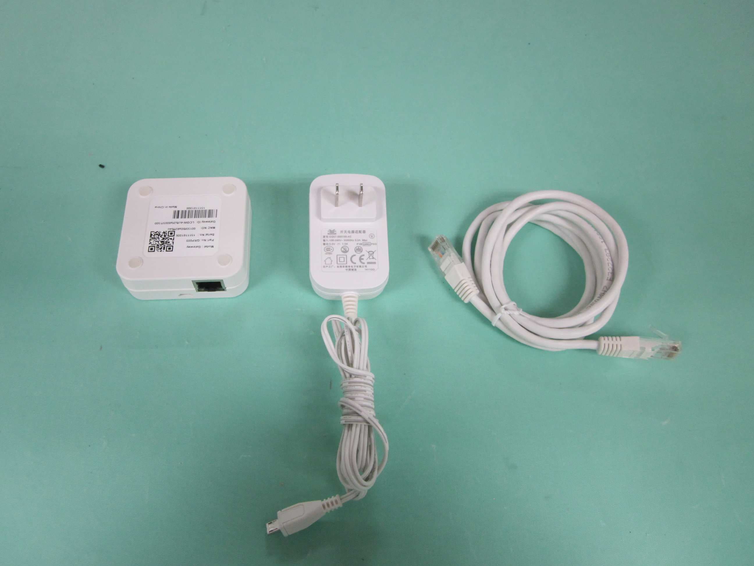
N9ZGRP009
Dec 22, 2015Gateway
Equipment Class
DTS - Digital Transmission System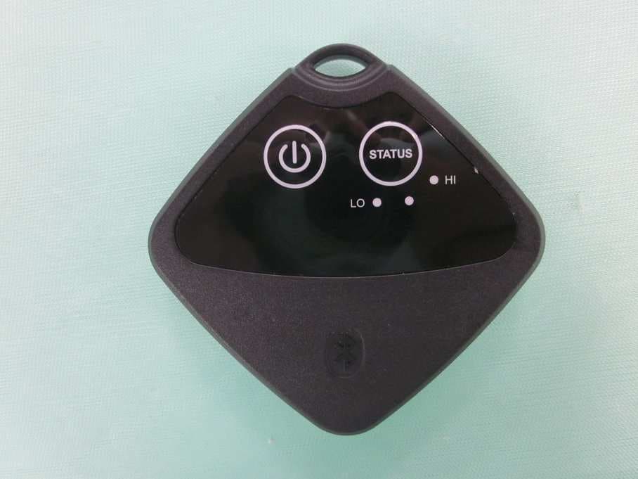
N9ZTLG002
Dec 03, 2015Temperature Logger
Equipment Class
DTS - Digital Transmission System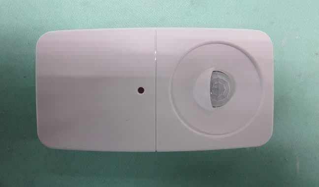
N9ZGRP001
Oct 22, 2015PIR Sensor
Equipment Class
DTS - Digital Transmission System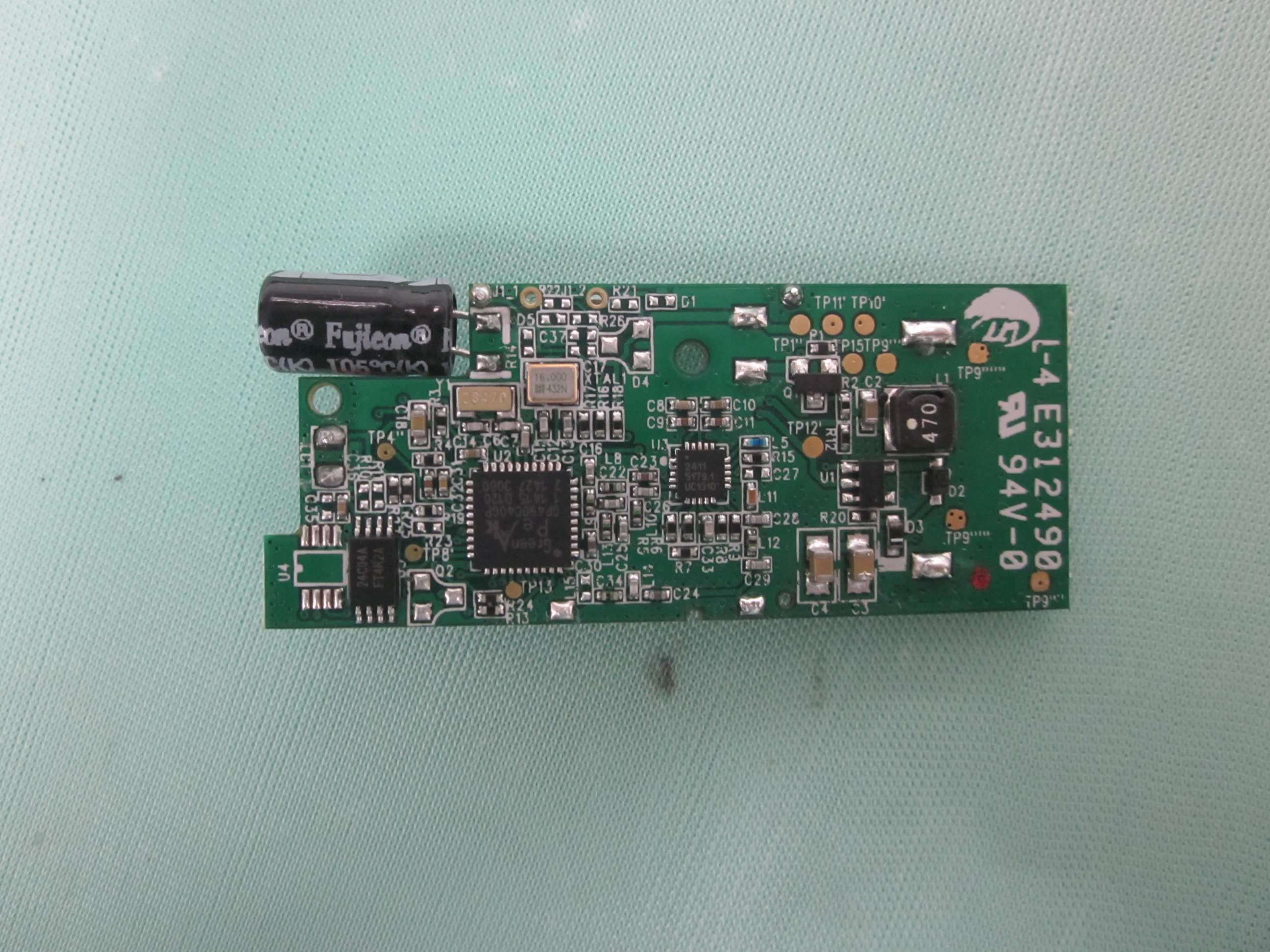
N9ZGRP002
Oct 22, 2015Door/Window Sensor
Equipment Class
DTS - Digital Transmission System
N9ZMAV233
Jul 02, 2015Wireless Kitchen Thermometer
Equipment Class
DSC - Part 15 Security/Remote Control Transmitter