N9ZGRP001PIR Sensor
Ewig Industries Macao Commercial Offshore Limited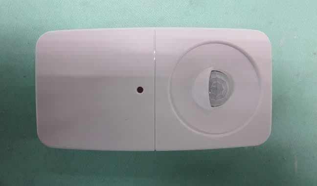
Click to zoom
Application Details
- Equipment Class
- DTS - Digital Transmission System
- Date of Grant
- Oct 22, 2015
- Application Purpose
- Original Equipment
- Date of Application
- Oct 22, 2015
- Equipment Note
- PIR Sensor
- Frequency Range
- 2405.00000000 - 2475.00000000
- Country
- Macau
Documents & Files
Document Text
Text extracted from the exhibit documents filed with the FCC. Open a document above to read the original.
Users Manual
User Instruction Manual Thank you for choosing the GRP Smart Home System. In the gift box you find the following essentials needed to benefit the most from GRP. Gateway device Power adapter USB cable Door/window sensor Water leakage sensor Temperature sensor Smartphone App Installation: To activate the system and to see the information GRP brings, you need to install the GRP App on your Smartphone. Whether you have a Smartphone with iOS or Android, GRP supports both. Depending on the type of device, go to the website link that we provided you can download the App for both iOS &Android via your Smartphone. Once the App is installed: 1. Open the App on your Smartphone; 2. Login with your credentials provided with the GRP package. Hardware Installation: GRP Smart Home System is designed with focus on comfort and ease of use. The installation process is no exception. Out of the box, GRP comes pre-installed. This means that once activated, all sensors are ready to work together and in combination with the right smartphones. Once everything is in place, GRP is ready to get to know the resident’s behavior and report on its well-being. Follow the instructions to correctly install your GRP system. Note: Make sure at least 20cm separation distance of installation points and user during normal operation. Gateway Install: 1. Connect the Gateway to the internet via the supplied Ethernet cable. Use a port on the internet modem or router labeled with “LAN” or “Ethernet”. Power the Gateway. 2. Connect the supplied USB cable to the power adaptor (5V), plug the smallest connector of the USB cable in the gateway. 3. Insert the power adaptor in a power outlet. The device will turn on and several lights start to blink. When the power light stays continuously on, the device is ready Gateway LED Indicator: 1. Power LED – Green LED. It does show Ethernet activities. 2. Zigbee LED – Orange LED. It is used to provide information on some special cases. 3. Error LED – Red LED. It is used to indicate error cases. Door/window Sensor Install: 1. Place the sensor body and magnet on door or window by double-side tape on the back. Make sure the dots on both devices are close to each other. 2. The gap of door or window must less than 10mm 3. Mobile app will display “open” or “close” related to corresponding actions. Water leakage sensor Install: 1. Paste the sensor by double-side tape on the install position you want to install; 2. Mobile app will display “leak” when the probe touch water; Water leakage sensor Probe Temperature sensor Install: 1. Paste the sensor by double-side tape on the install position you want to place; 2. Mobile App will display environment temperature; FCC Statement: This device complies with part 15 of the FCC Rules. Operation is subject to the following two conditions: (1) This device may not cause harmful interference, and (2) this device must accept any interference received, including interference that may cause undesired operation. This equipment has been tested and found to comply with the limits for a Class B digital device, pursuant to part 15 of the FCC Rules. These limits are designed to provide reasonable protection against harmful interference in a residential installation. This equipment generates, uses and can radiate radio frequency energy and, if not installed and used in accordance with the instructions, may cause harmful interference to radio communications. However, there is no guarantee that interference will not occur in a particular installation. If this equipment does cause harmful interference to radio or television reception, which can be determined by turning the equipment off and on, the user is encouraged to try to correct the interference by one or more of the following measures: —Reorient or relocate the receiving antenna. —Increase the separation between the equipment and receiver. —Connect the equipment into an outlet on a circuit different from that to which the receiver is connected. —Consult the dealer or an experienced radio/TV technician for help. Caution: Any changes or modifications not expressly approved by the party responsible for compliance could void the user's authority to operate the equipment. Temperature sensor
Users Manual
UserInstructionManual GatewayInstallation: 1.ConnecttheGatewaytotheinternetviathesuppliedEthernetcable.Useaportonthe internetmodemorrouterlabeledwith“LAN”or“Ethernet”.PowertheGateway. 2.ConnectthesuppliedUSBcabletothepoweradaptor(5V),plugthesmallestconnector oftheUSBcableinthegateway. 3.Insertthepoweradaptorinapoweroutlet.Thedevicewillturnonandseverallightsstart toblink.Whenthepowerlightstayscontinuouslyon,thedeviceisready GatewayLEDdirection: 1.GreenLED-Powerlight,andshowtheEthernetconnectisnormalornot; 2.OrangeLED-Pairing&Zigbee 3.RedLED-Error PIRSensorInstallation: 1.Openthecasingbydetachingthebackplatefromthedevice.PlacetheAAbatteries insidethesensor;Closethecasing,youwillheara“click”whendoneproperly. 2.Drillaholeintheholeatabout1.4metershigh.Usetheprovidedwallplugtoturnthe screwinthewall. 3.Mountthesensorbyslidingtheholeinthetopofthebackplateoverthescrewinthe wall.Makesurethelensispointingupwards. Door/w indow Sensor Insta llati on: 1.Place th e sensor body andmagneton door or window by double-sidedtapeon th e back. Make sure th e dotson bothdevices are close to each oth er. 2.The gapof door or window must less than10mm FCC Statement: This device complies with part 15 of the FCC Rules. Operation is subject to the following two conditions: (1) This device may not cause harmful interference, and (2) this device must accept any interference received, including interference that may cause undesired operation. This equipment has been tested and found to comply with the limits for a Class B digital device, pursuant to part 15 of the FCC Rules. These limits are designed to provide reasonable protection against harmful interference in a residential installation. This equipment generates, uses and can radiate radio frequency energy and, if not installed and used in accordance with the instructions, may cause harmful interference to radio communications. However, there is no guarantee that interference will not occur in a particular installation. If this equipment does cause harmful interference to radio or television reception, which can be determined by turning the equipment off and on, the user is encouraged to try to correct the interference by one or more of the following measures: —Reorient or relocate the receiving antenna. —Increase the separation between the equipment and receiver. —Connect the equipment into an outlet on a circuit different from that to which the receiver is connected. —Consult the dealer or an experienced radio/TV technician for help. Caution: Any changes or modifications not expressly approved by the party responsible for compliance could void the user's authority to operate the equipment.
External Photos
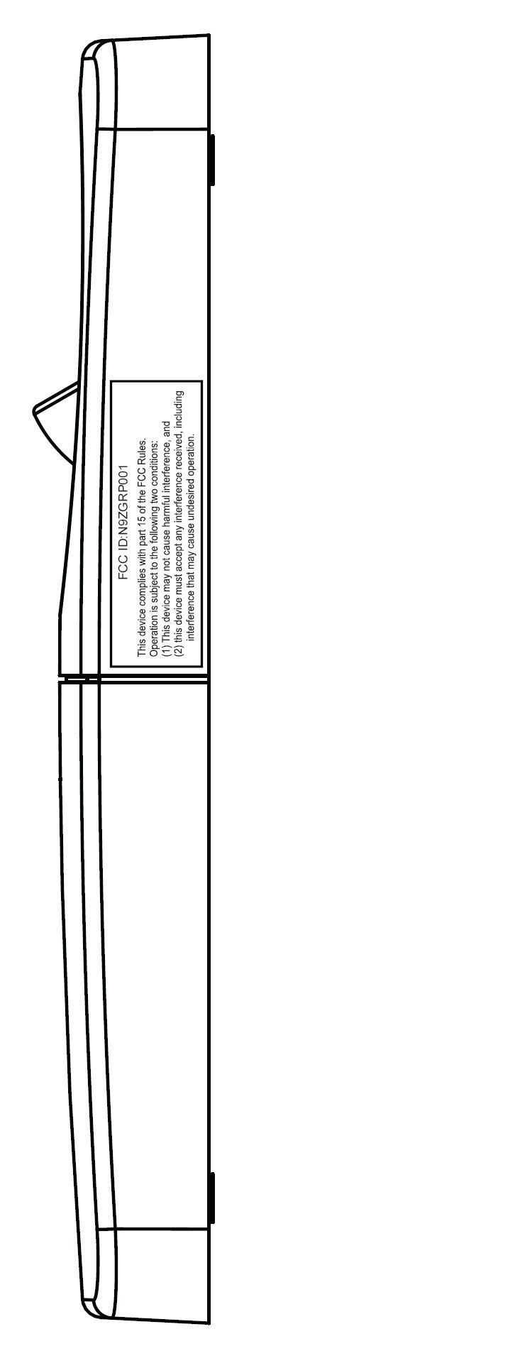
FCC ID: N9ZGRP001 PHOTOGRAPH OF THE PRODUCT FRONT VIEW OF THE PRODUCT REAR VIEW OF THE PRODUCT FCC ID: N9ZGRP001 PHOTOGRAPH OF THE PRODUCT LEFT VIEW OF THE PRODUCT RIGHT VIEW OF THE PRODUCT FCC ID: N9ZGRP001 PHOTOGRAPH OF THE PRODUCT TOP VIEW OF THE PRODUCT BTTOM VIEW OF THE PRODUCT
Internal Photos
FCC ID: N9ZGRP001 PHOTOGRAPH OF THE PRODUCT INNER CIRCUIT TOP VIEW FCC ID: N9ZGRP001 PHOTOGRAPH OF THE PRODUCT INNER CIRCUIT BOTTOM VIEW FCC ID: N9ZGRP001 PHOTOGRAPH OF THE PRODUCT
Test Report
STC Test Report Date: 2015-09-06 Page 1 of 31 No.: DM120816 Applicant: Ewig Industries Macao Commercial Offshore Limited Avenida Da Praia Grande No.619, EDF. Comercial Si Toi L6, Macau Manufacturer: Dong Guan Q&S Electronic Manufacturing Company Limited Yin Shan Industrial District, Fu Gang Village, Xiang Mang West Road, Qing Xi Town, Dongguan City, Guang Dong Province, China Description of Sample(s): Submitted sample(s) said to be Product: PIR Sensor Brand Name: EWIG Model Number: GRP001 FCC ID: N9ZGRP001 Date Sample(s) Received: 2015-08-26 Date Tested: 2015-08-31 to 2015-09-06 Investigation Requested: Perform ElectroMagnetic Interference measurement in accordance with FCC 47CFR [Codes of Federal Regulations] Part 15: 2014 and ANSI C63.4:2009 for FCC Certification. Conclusion(s): The submitted product COMPLIED with the requirements of Federal Communications Commission [FCC] Rules and Regulations Part 15. The tests were performed in accordance with the standards described above and on Section 2.2 in this Test Report. Remark(s): --- LONG Yun Jian, Along Authorized Signatory ElectroMagnetic Compatibility Department For and on behalf of STC (Dongguan) Company Limited STC Test Report Date: 2015-09-06 Page 2 of 31 No.: DM120816 CONTENT: Cover Page 1 of 31 Content Page 2 of 31 1.0 General Details 1.1 Test Laboratory Page 3 of 31 1.2 Equipment Under Test [EUT] Page 3 of 31 Description of EUT operation 1.3 Date of Order Page 3 of 31 1.4 Submitted Sample(s) Page 3 of 31 1.5 Test Duration Page 3 of 31 1.6 Country of Origin Page 3 of 31 2.0 Technical Details 2.1 Investigations Requested Page 4 of 31 2.2 Test Standards and Results Summary Page 4 of 31 3.0 Test Results 3.1 Emission Page 5-27 of 31 Appendix A List of Measurement Equipment Page 28 of 31 Appendix B Photographs of EUT Page 29-31 of 31 STC Test Report Date: 2015-09-06 Page 3 of 31 No.: DM120816 1.0 General Details 1.1 Test Laboratory STC (Dongguan) Company Limited EMC Laboratory 68 Fumin Nan Road, Dalang, Dongguan, Guangdong, China Telephone: (86 769) 81119888 Fax: (86 769) 81116222 1.2 Equipment Under Test [EUT] Description of Sample(s) Product: PIR Sensor Manufacturer: Dong Guan Q&S Electronic Manufacturing Company Limited Yin Shan Industrial District, Fu Gang Village, Xiang Mang West Road, Qing Xi Town, Dongguan City, Guang Dong Province, China Brand Name: EWIG Model Number: GRP001 Rating: 3.0Vd.c. (CR2430 battery x 1) 1.2.1 Description of EUT Operation The Equipment Under Test (EUT) is a PIR Sensor of Ewig Industries Macao Commercial Offshore Limited. the transmission signal is digital modulated with channel frequency range 2405-2475MHz. 1.3 Date of Order 2015-08-26 1.4 Submitted Sample(s): 1 Sample 1.5 Test Duration 2015-08-31 to 2015-09-06 1.6 Country of Origin China STC Test Report Date: 2015-09-06 Page 4 of 31 No.: DM120816 2.0 Technical Details 2.1 Investigations Requested Perform Electromagnetic Interference measurements in accordance with FCC 47CFR [Codes of Federal Regulations] Part 15: 2014 Regulations and ANSI C63.4:2009 for FCC Certification. According FCC KDB 558074 DTS Measurement Guidance, Duty cycle ≧98%. The device was realized by test software. 2.2 Test Standards and Results Summary Tables EMISSION Results Summary Test Condition Test Requirement Test Method Class / Test Result Severity Pass Fail N/A Output Power of Fundamental Emissions FCC 47CFR 15.247(b)(3) ANSI C63.4:2009 N/A Radiated Emissions FCC 47CFR 15.209 ANSI C63.4:2009 N/A Conducted Emissions FCC 47CFR 15.207 ANSI C63.4:2009 N/A Power Spectral Density FCC 47CFR 15.247(e) N/A N/A 6dB Bandwidth FCC 47CFR 15.247(a)(2) N/A N/A Band Edge Emissions FCC 47CFR 15.247(d) N/A N/A RF Exposure FCC 47CFR 15.247(i) N/A N/A Note: N/A - Not Applicable STC Test Report Date: 2015-09-06 Page 5 of 31 No.: DM120816 3.0 Test Results 3.1 Emission 3.1.1 Maximum Peak Output Power Test Requirement: FCC 47CFR 15.247(b)(3) Test Method: N/A Test Date: 2015-09-01 Mode of Operation: TX mode Test Method: The RF output of the EUT was connected to the peak power meter. All the attenuation or cable loss will be added to the measured maximum output power. The results are recorded in mW. Test Setup: Note: a temporary antenna connector was soldered to the RF output. EUT Peak Power Meter STC Test Report Date: 2015-09-06 Page 6 of 31 No.: DM120816 Limits for Peak Output Power of Fundamental & Harmonics Emissions [FCC 47CFR 15.247]: For Digital Transmission systems in 2400-2483.5 MHz Band: 1 Watt (30dBm) Results of Tx Mode GFSK (2405MHz to 2475MHz) : Pass (TX Unit) Maximum conducted output power Channel Frequency(MHz) Output Power(Watt) Low 2405 0.1021 Middle 2440 0.1167 High 2475 0.1112 Calculated measurement uncertainty : 30MHz to 1GHz 1.7dB 1GHz to 26GHz 1.7dB STC Test Report Date: 2015-09-06 Page 7 of 31 No.: DM120816 3.1.2 Radiated Emissions Test Requirement: FCC 47CFR 15.209 Test Method: ANSI C63.4:2009 Test Date: 2015-08-31 to 2015-09-01 Mode of Operation: Tx mode Test Method: The sample was placed 0.8m above the ground plane of semi-anechoic Chamber*. Measurements in both horizontal and vertical polarities were performed. During the test, each emission was maximized by: having the EUT continuously working, investigated all operating modes, rotated about all 3 axis (X, Y & Z) and considered typical configuration to obtain worst position, manipulating interconnecting cables, rotating turntable, varying antenna height from 1m to 4m in both horizontal and vertical polarizations. The emissions worst-case are shown in Test Results of the following pages. * Semi-anechoic chamber located on the G/F of “STC (Dongguan) Company Limited” with a metal ground plane filed with the FCC pursuant to section 2.948 of the FCC rules, with Registration Number: 629686. Test Setup: Measurement Receiver Computer Ground Plane Absorbers Absorbers placed on top of the ground plane are for measurements above 1000MHz only. Turn-table Distance = 3m Semi-Anechoic Chamber EUT STC Test Report Date: 2015-09-06 Page 8 of 31 …
Text truncated - open the document above for the full version.
Test Setup Photos
FCC ID: N9ZGRP001 PHOTOGRAPH OF THE PRODUCT MEASUREMENT OF RADIATED EMISSION TEST SET UP FCC ID: N9ZGRP001 PHOTOGRAPH OF THE PRODUCT
Contact Information
Applicant
Liu Binkky(Electronic Supervisor)
Test Firm
Hong Kong Standards and Testing CenterWison Wong
Technical Specifications
| # | Rule Parts | Frequency Range | Power Output |
|---|---|---|---|
| 1 | 15C | 2.40 GHz - 2.48 GHz | 117.00 mW |
Other Applications from Ewig Industries Macao Commercial Offshore Limited
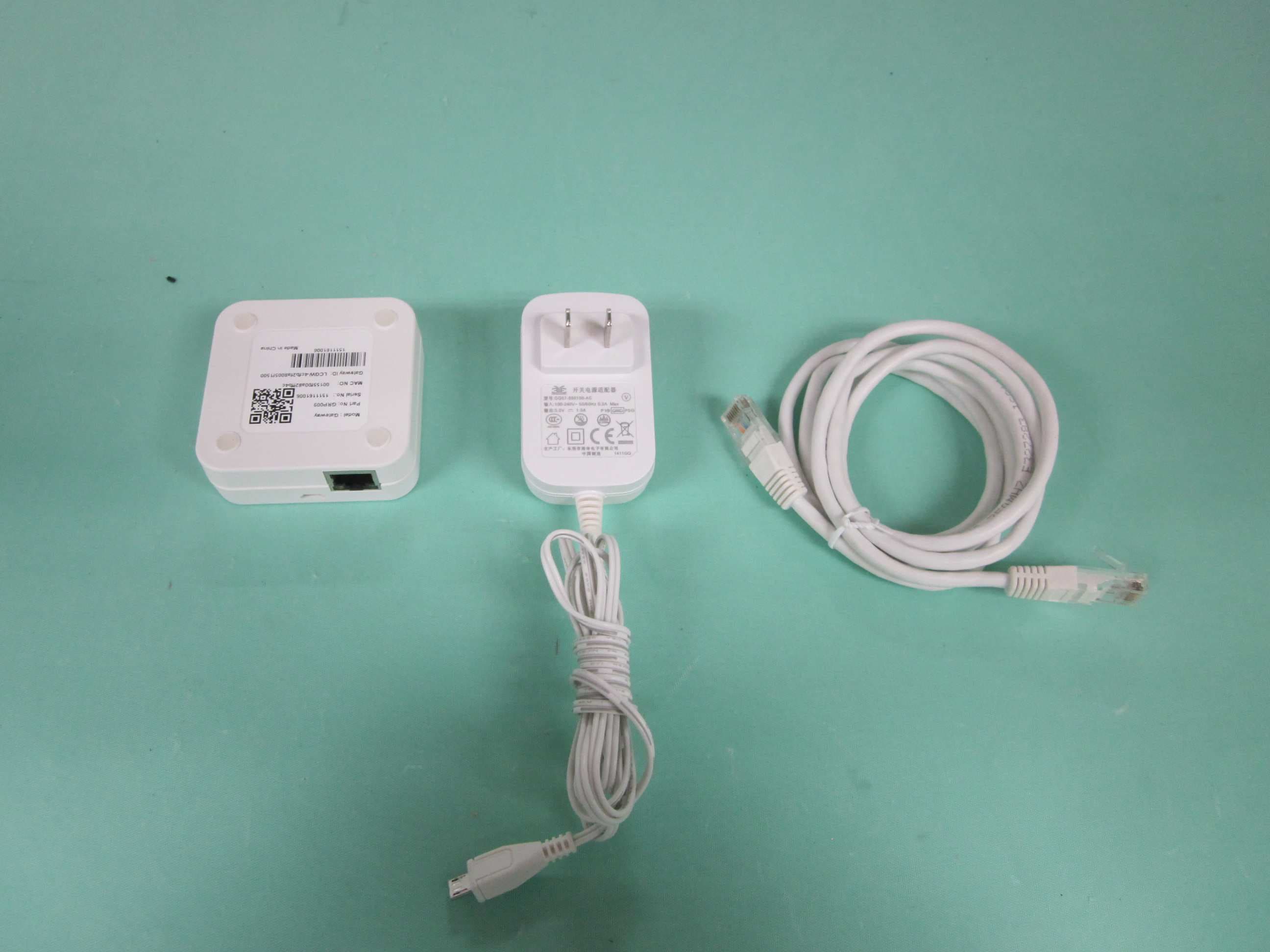
N9ZGRP009
Dec 22, 2015Gateway
Equipment Class
DTS - Digital Transmission System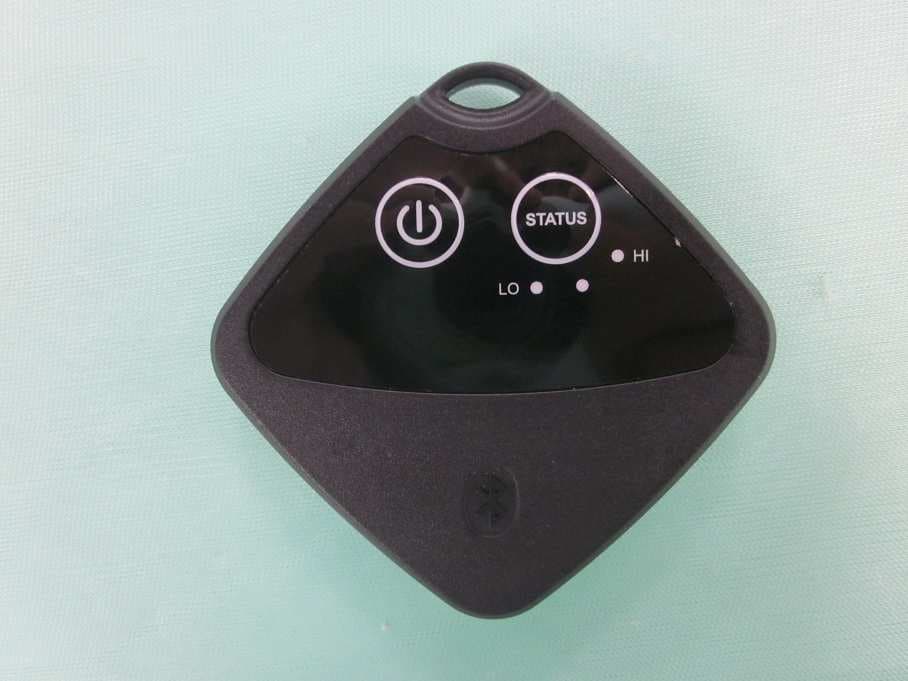
N9ZTLG002
Dec 03, 2015Temperature Logger
Equipment Class
DTS - Digital Transmission System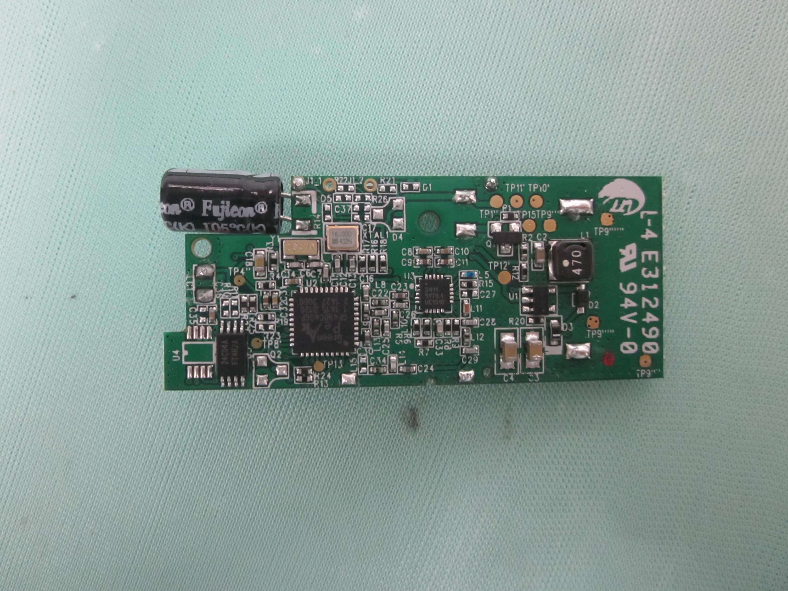
N9ZGRP002
Oct 22, 2015Door/Window Sensor
Equipment Class
DTS - Digital Transmission System
N9ZMAV233
Jul 02, 2015Wireless Kitchen Thermometer
Equipment Class
DSC - Part 15 Security/Remote Control Transmitter
N9ZTPX306
May 07, 2015Wireless Kitchen Thermometer
Equipment Class
DSC - Part 15 Security/Remote Control Transmitter