N9ZGRP009Gateway
Ewig Industries Macao Commercial Offshore Limited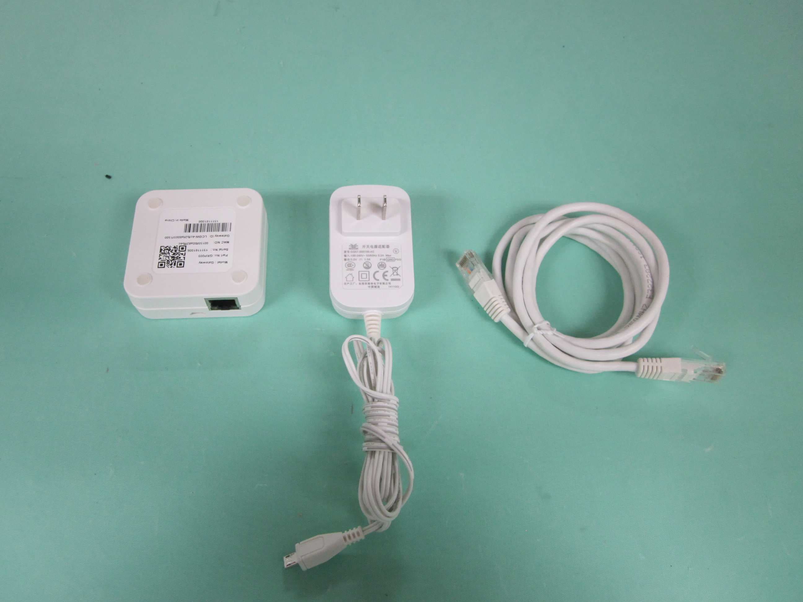
Click to zoom
Application Details
- Equipment Class
- DTS - Digital Transmission System
- Date of Grant
- Dec 22, 2015
- Application Purpose
- Original Equipment
- Date of Application
- Dec 22, 2015
- Equipment Note
- Gateway
- Frequency Range
- 2405.00000000 - 2475.00000000
- Country
- Macau
Documents & Files
Document Text
Text extracted from the exhibit documents filed with the FCC. Open a document above to read the original.
External Photos
N9ZGRP009 PHOTOGRAPH OF THE PRODUCT FRONT VIEW OF THE PRODUCT REAR VIEW OF THE PRODUCT N9ZGRP009 PHOTOGRAPH OF THE PRODUCT LEFT VIEW OF THE PRODUCT RIGHT VIEW OF THE PRODUCT N9ZGRP009 PHOTOGRAPH OF THE PRODUCT TOP VIEW OF THE PRODUCT BTTOM VIEW OF THE PRODUCT N9ZGRP009 PHOTOGRAPH OF THE PRODUCT
ID Label/Location Info
Label location
Internal Photos
N9ZGRP009 PHOTOGRAPH OF THE PRODUCT INNER CIRCUIT TOP VIEW N9ZGRP009 PHOTOGRAPH OF THE PRODUCT N9ZGRP009 PHOTOGRAPH OF THE PRODUCT INNER CIRCUIT BOTTOM VIEW N9ZGRP009 PHOTOGRAPH OF THE PRODUCT
Test Report
STC Test Report Date: 2015-11-26 Page 1 of 39 No.: DM120818 Applicant: Ewig Industries Macao Commercial Offshore Limited Avenida Da Praia Grande No.619, EDF. Comercial Si Toi L6, Macau Manufacturer: Dong Guan Q&S Electronic Manufacturing Company Limited Yin Shan Industrial District, Fu Gang Village, Xiang Mang West Road, Qing Xi Town, Dongguan City, Guang Dong Province, China Description of Sample(s): Submitted sample(s) said to be Product: Gateway Brand Name: EWIG Model Number: GRP009 FCC ID: N9ZGRP009 Date Sample(s) Received: 2015-08-26 Date Tested: 2015-09-01 to 2015-11-25 Investigation Requested: Perform ElectroMagnetic Interference measurement in accordance with FCC 47CFR [Codes of Federal Regulations] Part 15: 2014 and ANSI C63.10:2013 for FCC Certification. Conclusion(s): The submitted product COMPLIED with the requirements of Federal Communications Commission [FCC] Rules and Regulations Part 15. The tests were performed in accordance with the standards described above and on Section 2.2 in this Test Report. Remark(s): --- LONG Yun Jian, Along Authorized Signatory ElectroMagnetic Compatibility Department For and on behalf of STC (Dongguan) Company Limited STC Test Report Date: 2015-11-26 Page 2 of 39 No.: DM120818 CONTENT: Cover Page 1 of 39 Content Page 2 of 39 1.0 General Details 1.1 Test Laboratory Page 3 of 39 1.2 Equipment Under Test [EUT] Page 3 of 39 Description of EUT operation 1.3 Date of Order Page 4 of 39 1.4 Submitted Sample(s) Page 4 of 39 1.5 Test Duration Page 4 of 39 1.6 Country of Origin Page 4 of 39 2.0 Technical Details 2.1 Investigations Requested Page 5 of 39 2.2 Test Standards and Results Summary Page 5 of 39 3.0 Test Results 3.1 Emission Page 6-35 of 39 Appendix A List of Measurement Equipment Page 36 of 39 Appendix B Photographs of EUT Page 37-39 of 39 STC Test Report Date: 2015-11-26 Page 3 of 39 No.: DM120818 1.0 General Details 1.1 Test Laboratory STC (Dongguan) Company Limited EMC Laboratory 68 Fumin Nan Road, Dalang, Dongguan, Guangdong, China Telephone: (86 769) 81119888 Fax: (86 769) 81116222 1.2 Equipment Under Test [EUT] Description of Sample(s) Product: Gateway Manufacturer: Dong Guan Q&S Electronic Manufacturing Company Limited Yin Shan Industrial District, Fu Gang Village, Xiang Mang West Road, Qing Xi Town, Dongguan City, Guang Dong Province, China Brand Name: EWIG Model Number: GRP009 Rating: Input: 100-240Va.c. 50/60Hz 0.3A; Output: 5.0Vd.c. 1.0A. The AC/DC adaptor was provided by the applicant with following details: Brand name: N/A; Model no.: GQ07-050100-AC 1.2.1 Description of EUT Operation The Equipment Under Test (EUT) is a Zigbee Gateway of Ewig Industries Macao Commercial Offshore Limited. the transmission signal is digital modulated with channel frequency range 2405-2475MHz. The EUT consists of 2 antennae (Ant 0 and Ant 1), r.f. signal will only be transmitted from either Ant 0 or Ant 1 according to the reception condition. Measurement has been carried out on both antennae terminal, the worst case test results is recorded in this test report. STC Test Report Date: 2015-11-26 Page 4 of 39 No.: DM120818 1.3 Date of Order 2015-08-26 1.4 Submitted Sample(s): 1 Sample 1.5 Test Duration 2015-09-01 to 2015-11-25 1.6 Country of Origin China STC Test Report Date: 2015-11-26 Page 5 of 39 No.: DM120818 2.0 Technical Details 2.1 Investigations Requested Perform Electromagnetic Interference measurements in accordance with FCC 47CFR [Codes of Federal Regulations] Part 15: 2014 Regulations and ANSI C63.10:2013for FCC Certification. According FCC KDB 558074 DTS Measurement Guidance, Duty cycle ≧98%. The device was realized by test software. 2.2 Test Standards and Results Summary Tables EMISSION Results Summary Test Condition Test Requirement Test Method Class / Test Result Severity Pass Fail N/A Output Power of Fundamental Emissions FCC 47CFR 15.247(b)(3) ANSI C63.10:2013 N/A Radiated Emissions FCC 47CFR 15.209 ANSI C63.10:2013 N/A Conducted Emissions FCC 47CFR 15.207 ANSI C63.10:2013 N/A Power Spectral Density FCC 47CFR 15.247(e) N/A N/A 6dB Bandwidth FCC 47CFR 15.247(a)(2) N/A N/A Band Edge Emissions FCC 47CFR 15.247(d) N/A N/A RF Exposure FCC 47CFR 15.247(i) N/A N/A Note: N/A - Not Applicable STC Test Report Date: 2015-11-26 Page 6 of 39 No.: DM120818 3.0 Test Results 3.1 Emission 3.1.1 Maximum Peak Output Power Test Requirement: FCC 47CFR 15.247(b)(3) Test Method: N/A Test Date: 2015-09-01 Mode of Operation: Tx mode Test Method: The RF output of the EUT was connected to the peak power sensor, and the level measured by the peak power sensor will be displayed on the computer. All the attenuation or cable loss will be added to the measured maximum output power. The results are recorded in W. Test Setup: Note: a temporary antenna connector was soldered to the RF output. EUT Peak Power Sensor Computer STC Test Report Date: 2015-11-26 Page 7 of 39 No.: DM120818 Limits for Peak Output Power of Fundamental & Harmonics Emissions [FCC 47CFR 15.247]: For Digital Transmission systems in 2400-2483.5 MHz Band: 1 Watt (30dBm) ANT 0 Results of Tx Mode GFSK (2405MHz to 2475MHz) : Pass (Tx Unit) Maximum conducted output power Channel Frequency(MHz) Output Power(Watt) Low 2405 0.1112 Middle 2440 0.1064 High 2475 0.1021 ANT 1 Results of Tx Mode GFSK (2405MHz to 2475MHz) : Pass (Tx Unit) Maximum conducted output power Channel Frequency(MHz) Output Power(Watt) Low 2405 0.1021 Middle 2440 0.0993 High 2475 0.1014 Calculated measurement uncertainty : 30MHz to 1GHz 1.7dB 1GHz to 26GHz 1.7dB STC Test Report Date: 2015-11-26 Page 8 of 39 No.: DM120818 3.1.2 Radiated Emissions Test Requirement: FCC 47CFR 15.209 Test Method: ANSI C63.10:2013 Test Date: 2015-09-02 to 2015-11-25 Mode of Operation: Tx mode (Ant 0, worst case) Test Method: For emission measurements at or below 1 GHz, the sample was placed 0.8m above the ground plane of semi-anechoic Chamber*. For emission measurements above 1 GHz, the sample was placed 1.5m above the ground plane of semi-anechoic Chamber*. Measu…
Text truncated - open the document above for the full version.
Test Setup Photos
N9ZGRP009 PHOTOGRAPH OF THE PRODUCT MEASUREMENT OF RADIATED EMISSION TEST SET UP N9ZGRP009 PHOTOGRAPH OF THE PRODUCT MEASUREMENT OF CONDUCTED EMISSION TEST SET UP
Contact Information
Applicant
Liu Binkky(Electronic Supervisor)
Test Firm
Hong Kong Standards and Testing CenterWison Wong
Technical Specifications
| # | Rule Parts | Frequency Range | Power Output |
|---|---|---|---|
| 1 | 15C | 2.40 GHz - 2.48 GHz | 111.20 mW |
Other Applications from Ewig Industries Macao Commercial Offshore Limited
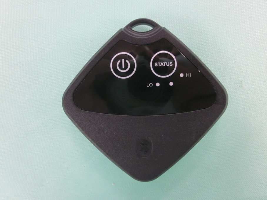
N9ZTLG002
Dec 03, 2015Temperature Logger
Equipment Class
DTS - Digital Transmission System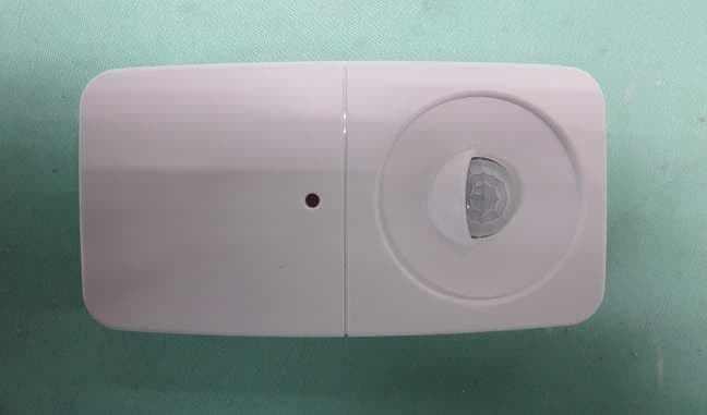
N9ZGRP001
Oct 22, 2015PIR Sensor
Equipment Class
DTS - Digital Transmission System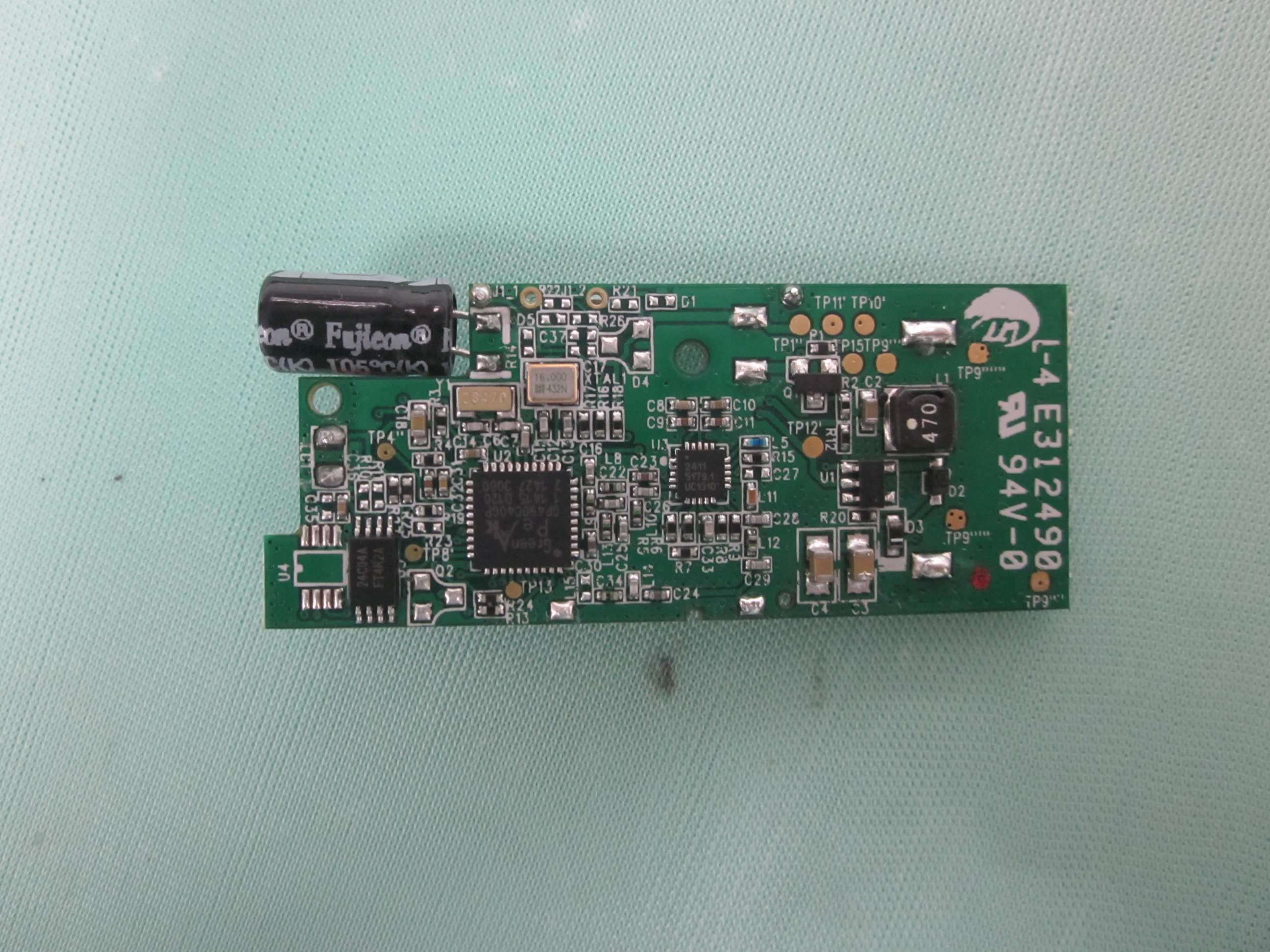
N9ZGRP002
Oct 22, 2015Door/Window Sensor
Equipment Class
DTS - Digital Transmission System
N9ZMAV233
Jul 02, 2015Wireless Kitchen Thermometer
Equipment Class
DSC - Part 15 Security/Remote Control Transmitter
N9ZTPX306
May 07, 2015Wireless Kitchen Thermometer
Equipment Class
DSC - Part 15 Security/Remote Control Transmitter