N9Z217S51Thermo Sensor Transmitter
Ewig Industries Macao Commercial Offshore Limited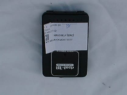
Click to zoom
Application Details
- Equipment Class
- DSC - Part 15 Security/Remote Control Transmitter
- Date of Grant
- Feb 17, 2003
- Application Purpose
- Original Equipment
- Date of Application
- Feb 17, 2003
- Equipment Note
- Thermo Sensor Transmitter
- Frequency Range
- 433.80000000 - 433.80000000
- Country
- Macau
Documents & Files
Document Text
Text extracted from the exhibit documents filed with the FCC. Open a document above to read the original.
Users Manual
RF 433Mhz Wireless Remote Sensor 217S51 Remote Sensor: Displays Outdoor Temperature Wireless Remote Sensor registration procedure 1. Place remote sensor near receiving unit. 2. Lift the click lock of the battery compartment and open the weatherproof battery cover. 3. Install 2 pcs of size AAA batteries according to polarity markings at the bottom of the battery compartment. 4. Once batteries are installed, push and hold the ìRESETî button for 3 seconds to send registration signal to the receiving unit. The LCD of the receiving unit will show the current temperature. 5. Once registration is complete, check that the rubber seal is in the cover groove, then close the battery cover tighly. Precautions a. Do not clean the units with abrasive or corrosive compound. It may scratch the plastic parts and corrode the electronic circuits. b. Do not subject the units to excessive force shock, dust, temperature or humidity, which may result in malfunctioning, shorter electronic life span, damage battery and distorted parts. c. Do not tamper with these unitsí internal components. Doing so will invalidate the warranty on the unit and may cause unnecessary damage battery and distorted parts. d. Do not subject the units to excessive exposure to direct sunlight. Although remote has splash proof design. Never immerse it in water or expose it to heavy rain. e. Always read the users manual thoroughly before operating the unit. Specification Recommended remote sensor operating range: Sensor with LCD display: -20∞C to +50∞C (-4∞F to +122∞F) Transmission range: Maximum 30 meters, open area Batteries: AAAsize x 2 pcs. (remote sensor) Battery life: 6 months Transmission frequency: 433.92 MHz ìModifications not authorized by the manufacturer may void users authority to operate this deviceî NOTE:This equipment has been tested and found to comply with the limits for a Class B digital device, pursuant to part 15 of the FCC Rules. These limits are designed to provide reasonable protection against harmful interference in a residential installation. This equipment generates, uses and can radiate radio frequency energy and, if not installed and used in accordance with the instructions, may cause harmful interference to radio communications. However, there is no guarantee that interference will not occur in a particular installation. If this equipment does not cause harmful interference to radio television reception, which can be determined by turning the equipment off and on, the user is encouraged to try to correct the interference by one or more of the following measures; -- Reorient or relocate the receiving antenna. -- Increase the separation between the equipment and receiver. -- Connect the equipment into an outlet on a circuit different from that to which the receiver is connected. -- Consult the dealer or an experienced radio/TV technician for help. CAUTION The above content is subject to change without prior notice. The displays printed in this manual may be different from the actual display because of printing limitations. The manufacturer and its suppliers hold no responsibility to you or any other person for any damage expenses, lost profits, or any other claims arisen by using this product. ï ï ï RF REMOTE SENSOR Lift off this part Bracket Stand AAA 1.5V AAA 1.5V
External Photos
PHOTOGRAPH OF THE PRODUCT FRONT VIEW OF THE PRODUCT REAR VIEW OF THE PRODUCT
Internal Photos
PHOTOGRAPH OF THE PRODUCT INNER CIRCUIT TOP VIEW INNER CIRCUIT BOTTOM VIEW
Test Report
Date: 2003-02-15 TEST REPORT Page 1 of 23 No.: HM109674 FCC PART 15 SUBPART C CERTIFICATION REPORT FOR LOW POWER TRANSMITTER TEST REPORT No.:HM109674 Equipment Under Test [EUT]:Thermo Sensor Transmitter Model Number:217S51 Applicant:Ewig Industries Co., Ltd. FCC ID :N9Z217S51 Date: 2003-02-15 TEST REPORT Page 2 of 23 No.: HM109674 CONTENT: Cover Page 1 of 23 Content Page 2-3 of 23 Conclusion Page 4 of 23 1.0 General Details 1.1Test Laboratory Page 5 of 23 1.2Applicant Details Page 5 of 23 Applicant HKSTC Code Number for Applicant Manufacturer 1.3Equipment Under Test [EUT] Page 6 of 23 Description of EUT operation 1.4Date of Order Page 6 of 23 1.5Submitted Sample Page 6 of 23 1.6Test Duration Page 6 of 23 1.7Country of Origin Page 6 of 23 1.8 Additional Information of EUT Page 7 of 23 2.0Technical Details 2.1Investigations Requested Page 8 of 23 2.2Test Standards and Results Summary Page 8 of 23 3.0Test Results 3.1Emission Page 9-14 of 23 3.2Bandwidth Measurement Page 15-16 of 23 Date: 2003-02-15 TEST REPORT Page 3 of 23 No.: HM109674 Appendix A List of Measurement Equipment Page 17 of 23 Appendix B Duty Cycle Correction During 100 msec Page 18-19 of 23 Appendix C Periodic Operation Page 20-21 of 23 Appendix D Photographs Page 22-23 of 23 Date: 2003-02-15 TEST REPORT Page 4 of 23 No.: HM109674 CONCLUSION The submitted product was deemed to have COMPLIED with the requirements of Federal Communications Commission [FCC] Rules and Regulations Part 15. The tests were performed in accordance with the standards described above and on Section 2.2 in this Test Report. Verify byPatrick Wong for Chief Executive Date: 2003-02-15 TEST REPORT Page 5 of 23 No.: HM109674 1.0 General Details 1.1Test Laboratory The Hong Kong Standards and Testing Centre Ltd. EMC Laboratory 10 Dai Wang Street, Taipo Industrial Estate New Territories, Hong Kong Telephone:852 2666 1888 Fax:852 2664 4353 1.2Applicant Details Applicant EWIG INDUSTRIES CO., LTD. 13/F., Houtex Ind’l Bldg., 16 Hung To Road, Kwun Tong, Kowloon, Hong Kong. Telephone:852 2951 6881 Fax:852 2343 5799 HKSTC Code Number for ApplicantEWI001 Manufacturer Q & S MANUFACTURING CO., LTD. Fu Gang District Xiang Mang Rd., Qing Xi Zhen, Dong Guang Shi, Guang Dong province, China Telephone:86 769 7733008 Fax:86 769 7731496 Date: 2003-02-15 TEST REPORT Page 6 of 23 No.: HM109674 1.3Equipment Under Test [EUT] Description of Sample Product:Thermo Sensor Transmitter Manufacturer:Ewig Industries Co., Ltd. Brand Name:Ewig Model Number:217S51 Input Voltage:3Vd.c (“AAA” size battery x 2) 1.3.1Description of EUT Operation The Equipment Under Test (EUT) is an Ewig Industries Co., Ltd., 433.8MHz remote control. The transmitter is an automatic transmitter. The EUT is to transmit RF signal while temperature measurement is changed. The EUT is for data transmission, Modulation by Data Code. Tape is pulses modulation. 1.4Date of Order 2003-01-17 1.5Submitted Sample(s): 2 Samples per model 1.6Test Duration 2003-01-25 1.7Country of Origin China Date: 2003-02-15 TEST REPORT Page 7 of 23 No.: HM109674 1.8Additional Information of EUT SubmittedNot Available User Manual Part List Circuit Diagram Printed Circuit Board [PCB] Layout Block diagram FCC ID Label Date: 2003-02-15 TEST REPORT Page 8 of 23 No.: HM109674 2.0Technical Details 2.1Investigations Requested Perform ElectroMagnetic Interference measurement in accordance with FCC 47CFR [Codes of Federal Regulations] Part 15 and ANSI C63.4:2000 for FCC Certification. 2.2Test Standards and Results Summary Tables EMISSION Results Summary Test ConditionTest RequirementTest MethodClass /Test Result Severit y PassFailedN/A Field Strength of Fundamental Emissions & Spurious Emissions FCC 47CFR 15.231eANSI C63.4:2000N/A Radiated Emissions, 30MHz to 1GHz FCC 47CFR 15.209ANSI C63.4:2000Class B Conducted Emissions on AC, 0.15MHz to 30MHz FCC 47CFR 15.207ANSI C63.4:2000Class B Note: N/A - Not Applicable Date: 2003-02-15 TEST REPORT Page 9 of 23 No.: HM109674 3.0 Test Results 3.1Emission 3.1.1Radiated Emissions Test Requirement:FCC 47CFR 15.231e Test Method:ANSI C63.4:2000 Test Date:2003-01-25 Mode of Operation:On mode Test Method: The sample was placed 0.8m above the ground plane on the OATS *. Measurements in both horizontal and vertical polarities were performed. During the test, each emission was maximized by: having the EUT continuously working, investigate all operating modes, rotated about all 3 axis (X, Y & Z) to obtain worst position, manipulating interconnecting cables, rotating turntable, varying antenna height from 1m to 4m in both horizontal and vertical polarization. The emissions worst-case are shown in Test Results of the following pages. *:OATS [Open Area Test Site] located at HKSTC with a metal ground plane on filed with the FCC pursuant to section 2.948 of the FCC rules, with Registration Number: 90657. Test Setup: EUT distance = 3m Pre -Amplifier Receiver Turn Table Computer Ground plane Date: 2003-02-15 TEST REPORT Page 10 of 23 No.: HM109674 Limits for Field Strength of Fundamental Emissions [FCC 47CFR 15.231e]: Frequency Range of Fundamental Field Strength of Fundamental Emission [Peak] Field Strength of Fundamental Emission [Average] [MHz] [μV/m][μV/m] 40.66-40.701,000100 70-13050050 130-174500 to 1,500 *50 to 150 * 174-2601,500150 260-4701,500 to 5,000 *150 to 500 * Above 4705,000500 ** Linear interpolations Where F is the frequency in MHz, the formula for calculating the maximum permitted fundamental field strengths are as follows: for the band 130-174 MHz, μV/m at meters=22.72727(F)-2454.545; for the band 260-470 MHz, μV/m at 3 meters =16.6667(F)-2833.3333. The maximum permissible unwanted emission level is 20dB below the maximum fundamental level. Results: CorrectionLimit **Antenna Factor @3mPolarity dB μ V/m μ V/m 433.8066.320.787.022387.243,466.8Vertical Field Strength Measured dB μ V/m μ V/m Field Strength of Fundamental Emissions Peak Value Frequency Level @3m Field Strength MHzdB μ V/m CorrectionLimit **Antenna Fact…
Text truncated - open the document above for the full version.
Test Setup Photos
TEST SET UP PHOTOGRAPH OF THE PRODUCT MEASUREMENT OF RADIATED EMISSION TEST SET UP
Contact Information
Applicant
Liu Binkky(Electronic Supervisor)
Test Firm
Hong Kong Standards & Testing Cen.Wilson Wong
Technical Specifications
| # | Rule Parts | Frequency Range | Power Output |
|---|---|---|---|
| 1 | 15.231(e) | 433.8 MHz - 433.8 MHz | - |
Other Applications from Ewig Industries Macao Commercial Offshore Limited
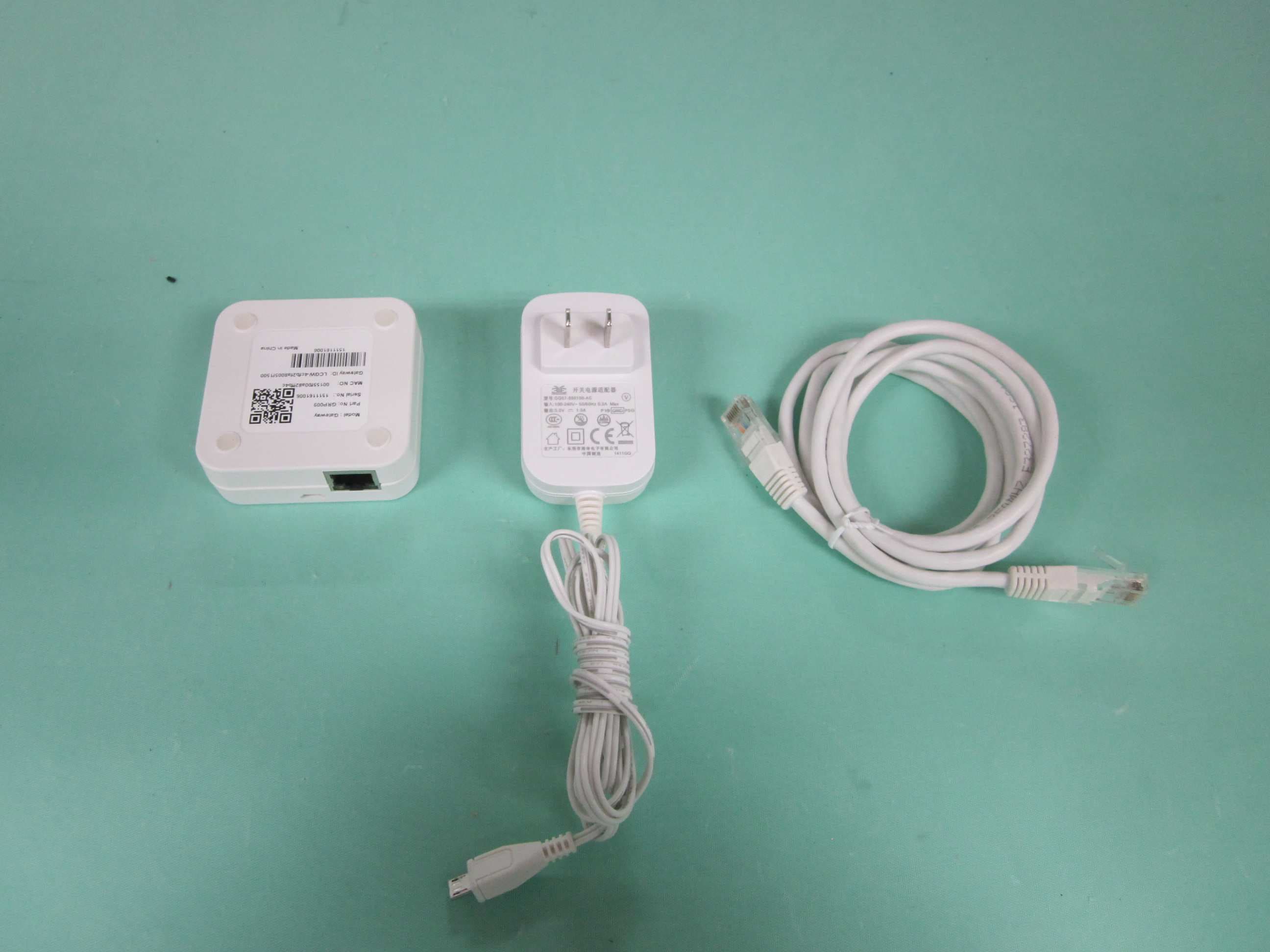
N9ZGRP009
Dec 22, 2015Gateway
Equipment Class
DTS - Digital Transmission System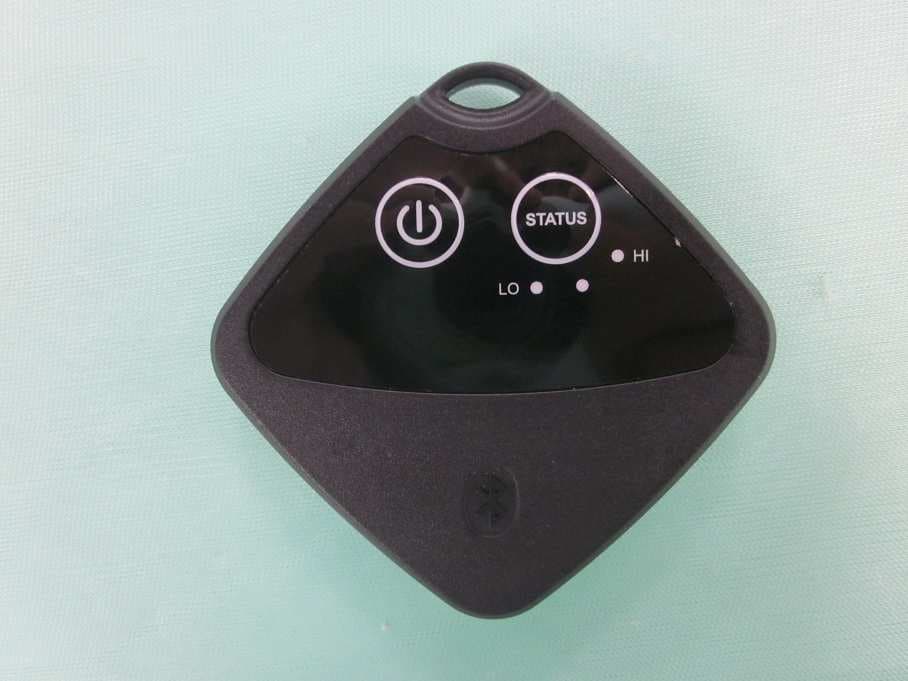
N9ZTLG002
Dec 03, 2015Temperature Logger
Equipment Class
DTS - Digital Transmission System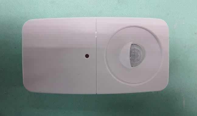
N9ZGRP001
Oct 22, 2015PIR Sensor
Equipment Class
DTS - Digital Transmission System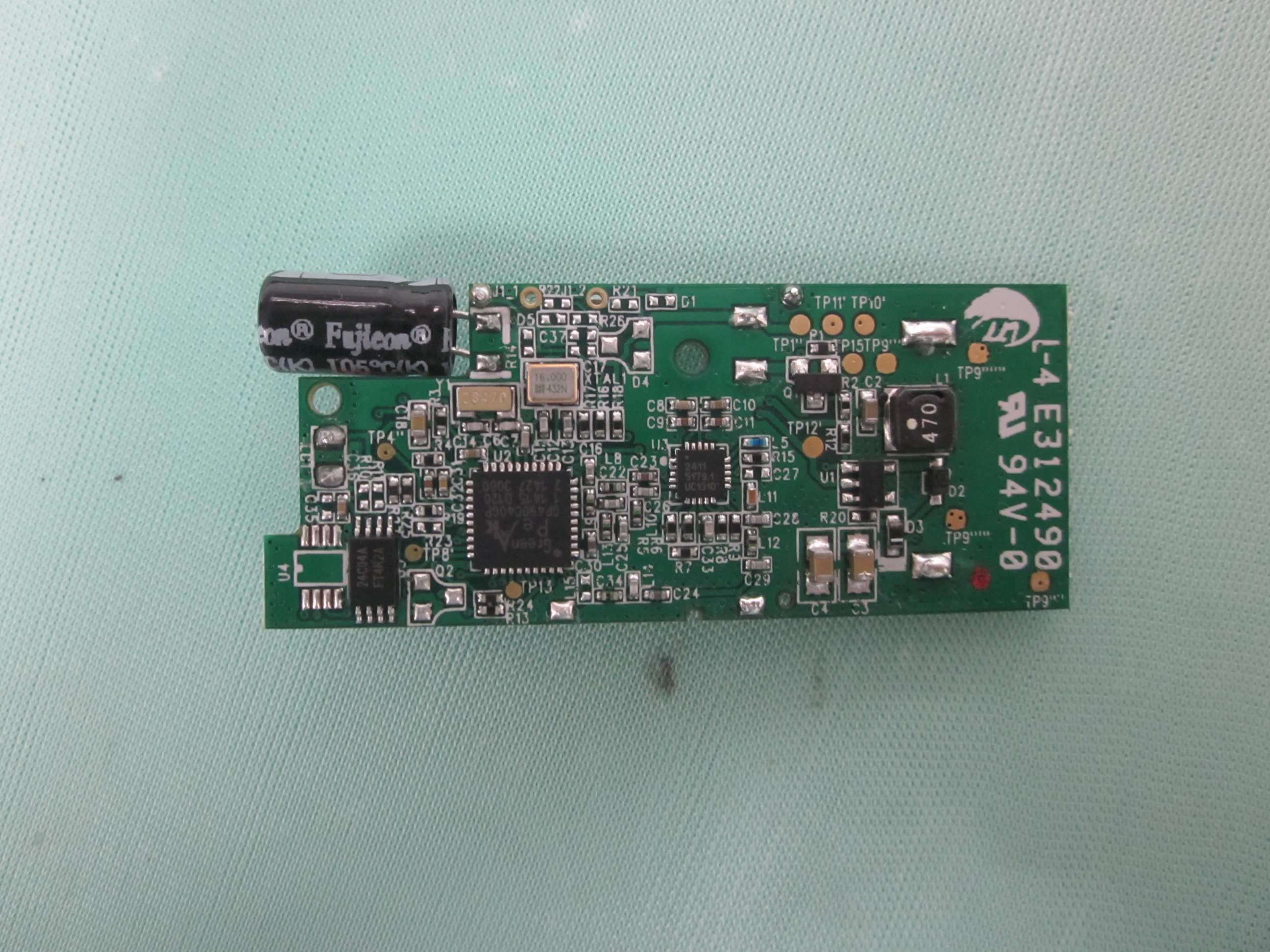
N9ZGRP002
Oct 22, 2015Door/Window Sensor
Equipment Class
DTS - Digital Transmission System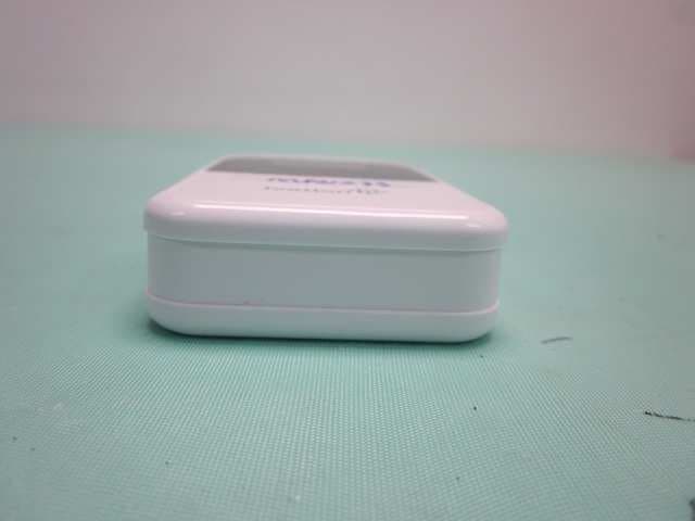
N9ZMAV233
Jul 02, 2015Wireless Kitchen Thermometer
Equipment Class
DSC - Part 15 Security/Remote Control Transmitter