N9Z693200Wireless Food Thermometer
Ewig Industries Macao Commercial Offshore Limited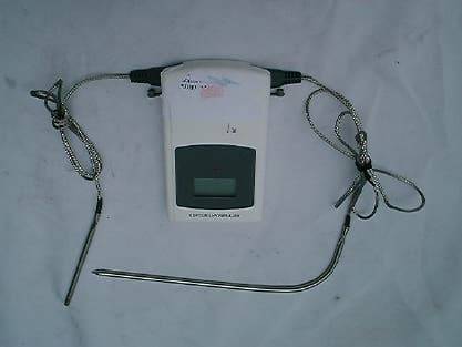
Click to zoom
Application Details
- Equipment Class
- DSC - Part 15 Security/Remote Control Transmitter
- Date of Grant
- May 22, 2003
- Application Purpose
- Original Equipment
- Date of Application
- May 22, 2003
- Equipment Note
- Wireless Food Thermometer
- Frequency Range
- 433.92000000 - 433.92000000
- Country
- Macau
Documents & Files
Document Text
Text extracted from the exhibit documents filed with the FCC. Open a document above to read the original.
Users Manual
Ewig Industries Co LtdSmoker thermometer Prepared By: Tony WuDated: March 26, 2003 1 OPERATION MANUAL Ideal for smoking, our remote thermometer allows you to monitor cooking progress from up to 100 feet away. Before using the remote thermometer, please read the Essential Safety Information. Inside this package, you will find: 1. Receiving unit (1) 2. Transmitter unit (1) 3. Detachable 3 feet stainless steel probe sensor and wire for food temperature measurement (1) 4. Detachable 2 feet stainless steel probe sensor and wire for smoker air temperature measurement (1) 5. AAA batteries (4) (Super Heavy Duty) Receiver Features: LCD (Liquid Crystal Display): This screen shows all icons, temperature readings and time displays. CLIP: The removable clip allows you to attach the receiver to you apron or belt, so you can keep the unit with you as you move around the house or yard. STAND: The sing-out stand allows you to stand the receiver on a counter or tabletop. BATTERY COMPARTMENT: Holds 2 AAA batteries Functions of Buttons on the Receiver: Thermometer mode (smoker/food) Timer mode (timer/food) 1SMOKER-HI/HRSet maximum Smoker temperature Set hours 2SMOKER-LO/MINSet minimum Smoker temperature Set minutes 3FOOD-HI/CLEARSet maximum Food temperature Clear timer 4Alert/ START/STOPAlarm on/off (hold to change °C/°F) Timer start/stop (hold to change °C/°F) 5Light/MODELight on for 5 seconds (hold to switch between 2 modes) Light on for 5 seconds (hold to switch between 2 modes) 6ON/OFFTo turn on/off receiver unitTo turn on/off receiver unit Transmitter Features: LCD (Liquid Crystal Display): Ewig Industries Co LtdSmoker thermometer Prepared By: Tony WuDated: March 26, 2003 2 This screen automatically toggles to displays the temperatures of the both probe sensors periodically (readings of probe only in °F). METAL HOOK for hanging, or reversed to use as a stand BATTERY COMPARTMENT: Holds 2 AAA batteries PLUG IN JACK for stainless steel FOOD probe sensor PLUG IN JACK for stainless steel SMOKER probe sensor Functions of Buttons on the Transmitter: 1. TX: Before first use, press and hold to register radio frequency with Receiver (see “Getting Started” below). 2. ON/OFF: Turn the transmitter unit on or off. Installing Batteries Make sure both receiver and transmitter units have the ON/OFF switch set to OFF. Open the battery compartments on the receiver and transmitter. Insert two AAA batteries into each compartment. Getting Started Before first use, you’ll need to set the receiver to register the radio frequency signal from the transmitter. This is called the “registration procedure”. 1. Plug the stainless steel probe sensors into the plug-in jacks on the transmitter matching the FOOD and SMOKER markings. 2. Using the ON/OFF switches, first turn on the receiver (ON/OFF switch at back) (display shows “- - - “ blinking). Then turn on the transmitter (ON/OFF switch inside battery compartment – which can be open using a coin). 3. The registration procedure is complete when the receiver beeps and the LCD displays the current temperatures for both smoker and food (provided both probes are inserted) If the registration procedure fails, the readings will show “- - - “ steady. Use ON/OFF switch to reset the receiver, and press the TX button (located on the rear of the transmitter) and hold for 2 seconds. This needs to be done within 60 seconds of turning the receiver on in order for the receiver to register the signal from the transmitter. Once TX is released. It will take several seconds for the receiver to register. If you don’t hear a beep within 5-10 seconds, press and hold TX again. Cooking According to Settings Our remote thermometer features programmable cooking temperature settings for foods safety. The temperatures displayed to the left of the LCD screen will show the set temperatures. To show and set maximum and minimum smoker temperature 1. Hold Light/MODE button to select smoker mode. The lower display will show a small SMOKER icon and temperature reading Ewig Industries Co LtdSmoker thermometer Prepared By: Tony WuDated: March 26, 2003 3 2. Press SMOKER-HI/HR or SMOKER-LO/MIN. The lower display will show a small HI icon (or LO icon) and the set maximum (or minimum) temperature for the smoker (automatically exit after 5 seconds) 3. Hold SMOKER-HI/HR (or SMOKER-LO/MIN) to enter setting mode (display flashing) 4. Press SMOKER-HI/HR (or SMOKER-LO/MIN) repeatedly to set the desired temperature (hold to fast forward) 5. Press MODE to confirm and return to normal mode To show and set max food temperature 1. Press FOOD-HI/CLEAR. The upper display will show a small HI icon and the set maximum temperature for the food (automatically exit after 5 seconds). 2. Hold FOOD-HI/CLEAR to enter setting mode (display flashing ) 3. Press FOOD-HI/CLEAR repeatedly to set the desired temperature (hold to fast forward) 4. Press MODE to confirm and return to normal mode To turn on the temperature alarm 1. Press Alert/ START/STOP to activate the temperature alarms for Smoker and Food. The alarm icons will be on at the upper and lower display. 2. For smoker cooking, insert the FOOD probe into the thickest part of the meat, place meat in the smoker and close the door. Make sure the probe is not touching a bone or any heavy fat areas. 3. The receiver will beep continuously, and the alarm icon and probe temperature display will blink when one of the following conditions happens: When the actual food temperature reached and exceeded the maximum FOOD set temperature, & When the actual smoker temperature reached and exceeded the maximum SMOKER set temperature, or fell below the minimum SMOKER set temperature. Note: The SMOKER – LO alarm will not happen if the first temperature reading is originally lower than the SMOKER set minimum temperature. 4. Press the Alert/ START/STOP to de-activate the alarm. Using the Timer Function The minimum setting for the timer is 1 minute, and the maximum setting is 24 hours. Times less than 10 hours are di…
Text truncated - open the document above for the full version.
External Photos
PHOTOGRAPH OF THE PRODUCT FRONT VIEW OF THE PRODUCT REAR VIEW OF THE PRODUCT
Internal Photos
PHOTOGRAPH OF THE PRODUCT INNER CIRCUIT TOP VIEW INNER CIRCUIT BOTTOM VIEW
Operational Description
FCC ID: N9Z693200 Circuit Description The 433MHz crystal oscillator drives the base of Q8 the final/buffer amplifier. The modulation provided by IC (W74IC260). The output of Q8 has the matching network consisting of L6 and C25 that limit the harmonic content and effect the proper coupling of the antenna to the output stage. Antenna, Ground and Power Source There is no external antenna. There is no external ground connection. The ground is only that of the printed circuit board. Electric current is supplied by a 3 Volt (“AAA” size battery x 2) primary battery
Test Report
Date: 2003-05-09 TEST REPORT Page 1 of 24 No.: HM110008 FCC PART 15 SUBPART C CERTIFICATION REPORT FOR LOW POWER TRANSMITTER TEST REPORT No.:HM110008 Equipment Under Test [EUT]:Smoker / Food RF Wireless Thermometer Model Number:693200 Applicant:Ewig Industries Co., Ltd. FCC ID :N9Z693200 Date: 2003-05-09 TEST REPORT Page 2 of 24 No.: HM110008 CONTENT: Cover Page 1 of 24 Content Page 2-3 of 24 Conclusion Page 4 of 24 1.0General Details 1.1Test Laboratory Page 5 of 24 1.2Applicant Details Page 5 of 24 Applicant HKSTC Code Number for Applicant Manufacturer 1.3Equipment Under Test [EUT] Page 6 of 24 Description of EUT operation 1.4Date of Order Page 6 of 24 1.5Submitted Sample Page 6 of 24 1.6Test Duration Page 6 of 24 1.7Country of Origin Page 6 of 24 1.8 Additional Information of EUT Page 7 of 24 2.0Technical Details 2.1Investigations Requested Page 8 of 24 2.2Test Standards and Results Summary Page 8 of 24 3.0Test Results 3.1Emission Page 9-14 of 24 3.2Bandwidth Measurement Page 15-16 of 24 Date: 2003-05-09 TEST REPORT Page 3 of 24 No.: HM110008 Appendix A List of Measurement Equipment Page 17 of 24 Appendix B Duty Cycle Correction During 100 msec Page 18-19 of 24 Appendix C Periodic Operation Page 20-21 of 24 Appendix D Photographs Page 23-24 of 24 Date: 2003-05-09 TEST REPORT Page 4 of 24 No.: HM110008 CONCLUSION The submitted product was deemed to have COMPLIED after modification by customer with the requirements of Federal Communications Commission [FCC] Rules and Regulations Part 15. The tests were performed in accordance with the standards described above and on Section 2.2 in this Test Report. Verified byPatrick Wong for Chief Executive Date: 2003-05-09 TEST REPORT Page 5 of 24 No.: HM110008 1.0General Details 1.1Test Laboratory The Hong Kong Standards and Testing Centre Ltd. EMC Laboratory 10 Dai Wang Street, Taipo Industrial Estate New Territories, Hong Kong Telephone:852 2666 1888 Fax:852 2664 4353 1.2Applicant Details Applicant EWIG INDUSTRIES CO., LTD. 13/F., Houtex Ind’l Bldg., 16 Hung To Road, Kwun Tong, Kowloon, Hong Kong. HKSTC Code Number for ApplicantEWI001 Manufacturer EWIG INDUSTRIES CO., LTD. 13/F., Houtex Ind’l Bldg., 16 Hung To Road, Kwun Tong, Kowloon, Hong Kong. Date: 2003-05-09 TEST REPORT Page 6 of 24 No.: HM110008 1.3Equipment Under Test [EUT] Description of Sample Product:Smoker / Food RF Wireless Thermometer Manufacturer:Ewig Industries Co., Ltd. Brand Name:Ewig Model Number:693200 Input Voltage:3Vd.c (“AAA” size battery x 2) 1.3.1Description of EUT Operation The Equipment Under Test (EUT) is an Ewig Industries Co., Ltd., 433.8MHz remote control. The transmitter is an automatic transmitter. The EUT is to transmit RF signal while temperature measurement is changed. The EUT is for data transmission, Modulation by Data Code. Tape is pulses modulation. 1.4Date of Order 2003-03-17 1.5Submitted Sample(s): 2 Samples per model 1.6Test Duration 2003-05-07 1.7Country of Origin China Date: 2003-05-09 TEST REPORT Page 7 of 24 No.: HM110008 1.8Additional Information of EUT SubmittedNot Available User Manual Part List Circuit Diagram Printed Circuit Board [PCB] Layout Block diagram FCC ID Label Date: 2003-05-09 TEST REPORT Page 8 of 24 No.: HM110008 2.0Technical Details 2.1Investigations Requested Perform ElectroMagnetic Interference measurement in accordance with FCC 47CFR [Codes of Federal Regulations] Part 15 and ANSI C63.4:2000 for FCC Certification. 2.2Test Standards and Results Summary Tables EMISSION Results Summary Test ConditionTest RequirementTest MethodClass /Test Result SeverityPassFailedN/A Field Strength of Fundamental Emissions & Spurious Emissions FCC 47CFR 15.231eANSI C63.4:2000N/A Radiated Emissions, 30MHz to 1GHz FCC 47CFR 15.209ANSI C63.4:2000Class B Conducted Emissions on AC, 0.15MHz to 30MHz FCC 47CFR 15.207ANSI C63.4:2000Class B Note: N/A - Not Applicable Date: 2003-05-09 TEST REPORT Page 9 of 24 No.: HM110008 3.0Test Results 3.1Emission 3.1.1Radiated Emissions Test Requirement:FCC 47CFR 15.231e Test Method:ANSI C63.4:2000 Test Date:2003-05-07 Mode of Operation:On mode Test Method: The sample was placed 0.8m above the ground plane on the OATS *. Measurements in both horizontal and vertical polarities were performed. During the test, each emission was maximized by: having the EUT continuously working, investigate all operating modes, rotated about all 3 axis (X, Y & Z) to obtain worst position, manipulating interconnecting cables, rotating turntable, varying antenna height from 1m to 4m in both horizontal and vertical polarization. The emissions worst-case are shown in Test Results of the following pages. *:OATS [Open Area Test Site] located at HKSTC with a metal ground plane on filed with the FCC pursuant to section 2.948 of the FCC rules, with Registration Number: 90657. Test Setup: EUT distance = 3m Pre -Amplifier Receiver Turn Table Computer Ground plane Date: 2003-05-09 TEST REPORT Page 10 of 24 No.: HM110008 Limits for Field Strength of Fundamental Emissions [FCC 47CFR 15.231e]: Frequency Range of Fundamental Field Strength of Fundamental Emission [Peak] Field Strength of Fundamental Emission [Average] [MHz][μV/m][μV/m] 40.66-40.701,000100 70-13050050 130-174500 to 1,500 *50 to 150 * 174-2601,500150 260-4701,500 to 5,000 *150 to 500 * Above 4705,000500 ** Linear interpolations Where F is the frequency in MHz, the formula for calculating the maximum permitted fundamental field strengths are as follows: for the band 130-174 MHz, μV/m at meters=22.72727(F)-2454.545; for the band 260-470 MHz, μV/m at 3 meters =16.6667(F)-2833.3333. The maximum permissible unwanted emission level is 20dB below the maximum fundamental level. Results: CorrectionLimit **Antenna Factor @3mPolarity dB μ V/m μ V/m 433.8161.420.782.112735.043,968.5Vertical μ V/m Field Strength of Fundamental Emissions Peak Value Frequency Level @3m Field Strength MHzdB μ V/m Field Strength Measured dB μ V/m According to FCC 47CFR15.35, the limit on the radio frequency emissions as measured …
Text truncated - open the document above for the full version.
Test Setup Photos
TEST SET UP PHOTOGRAPH OF THE PRODUCT MEASUREMENT OF RADIATED EMISSION TEST SET UP
Contact Information
Applicant
Liu Binkky(Electronic Supervisor)
Technical Contact
MET Laboratories Inc.Chris Harvey
[email protected]410-354-3300
914 W. Patapsco Avenue · Baltimore, Maryland · United States
Test Firm
Hong Kong Standards & Testing Cen.Wilson Wong
Technical Specifications
| # | Rule Parts | Frequency Range | Power Output |
|---|---|---|---|
| 1 | 15.231(e) | 433.92 MHz - 433.92 MHz | - |
Other Applications from Ewig Industries Macao Commercial Offshore Limited
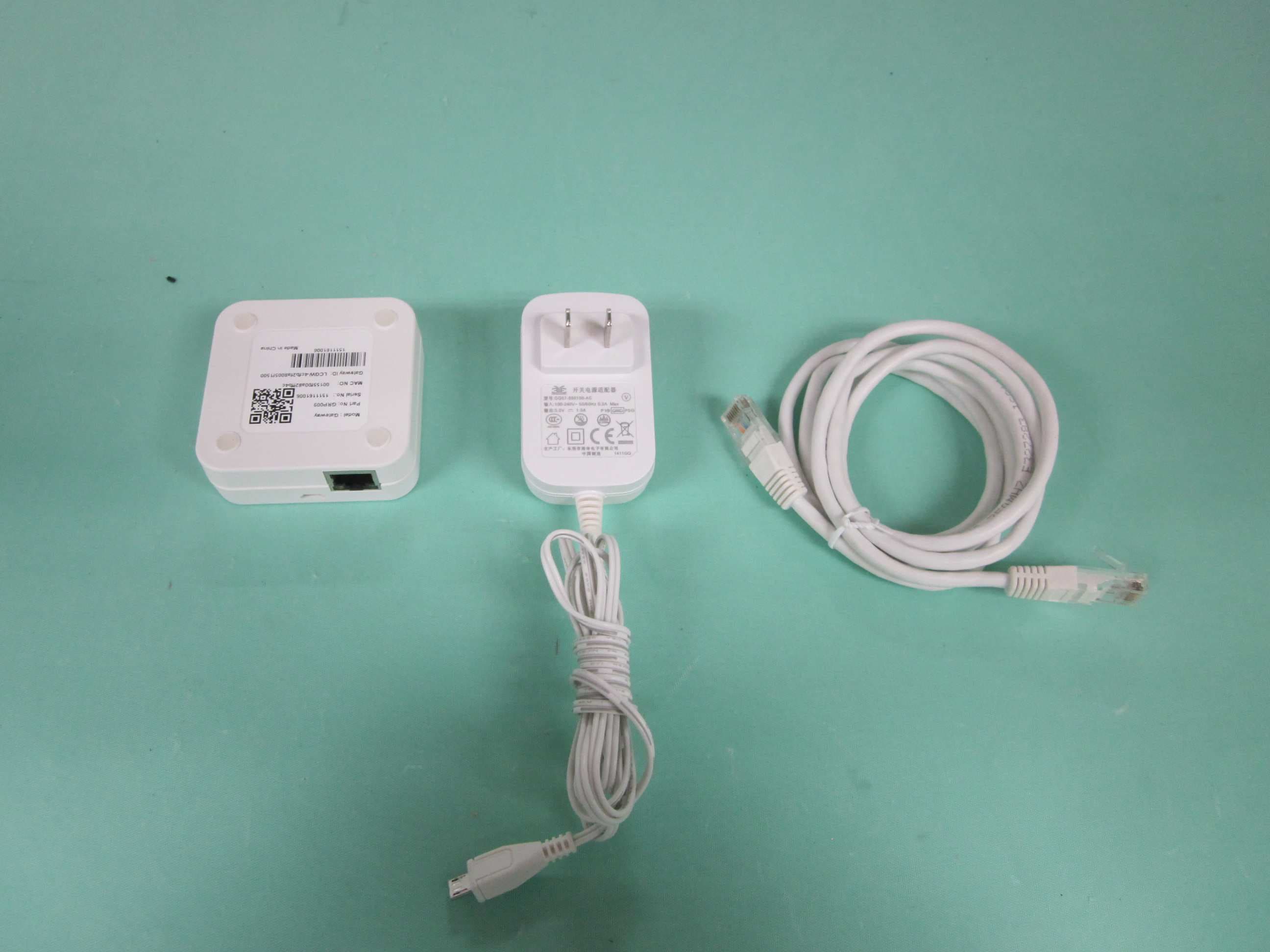
N9ZGRP009
Dec 22, 2015Gateway
Equipment Class
DTS - Digital Transmission System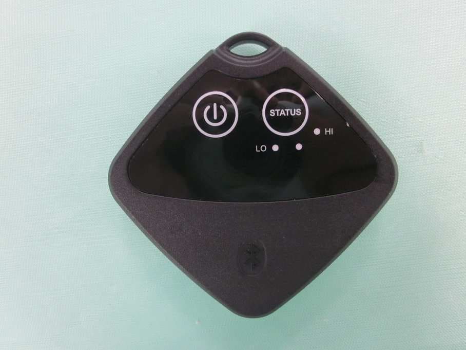
N9ZTLG002
Dec 03, 2015Temperature Logger
Equipment Class
DTS - Digital Transmission System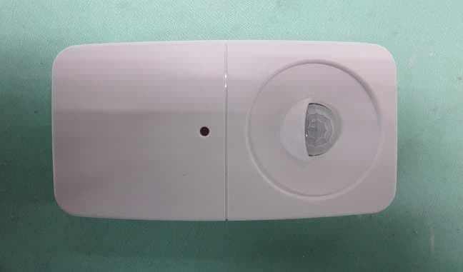
N9ZGRP001
Oct 22, 2015PIR Sensor
Equipment Class
DTS - Digital Transmission System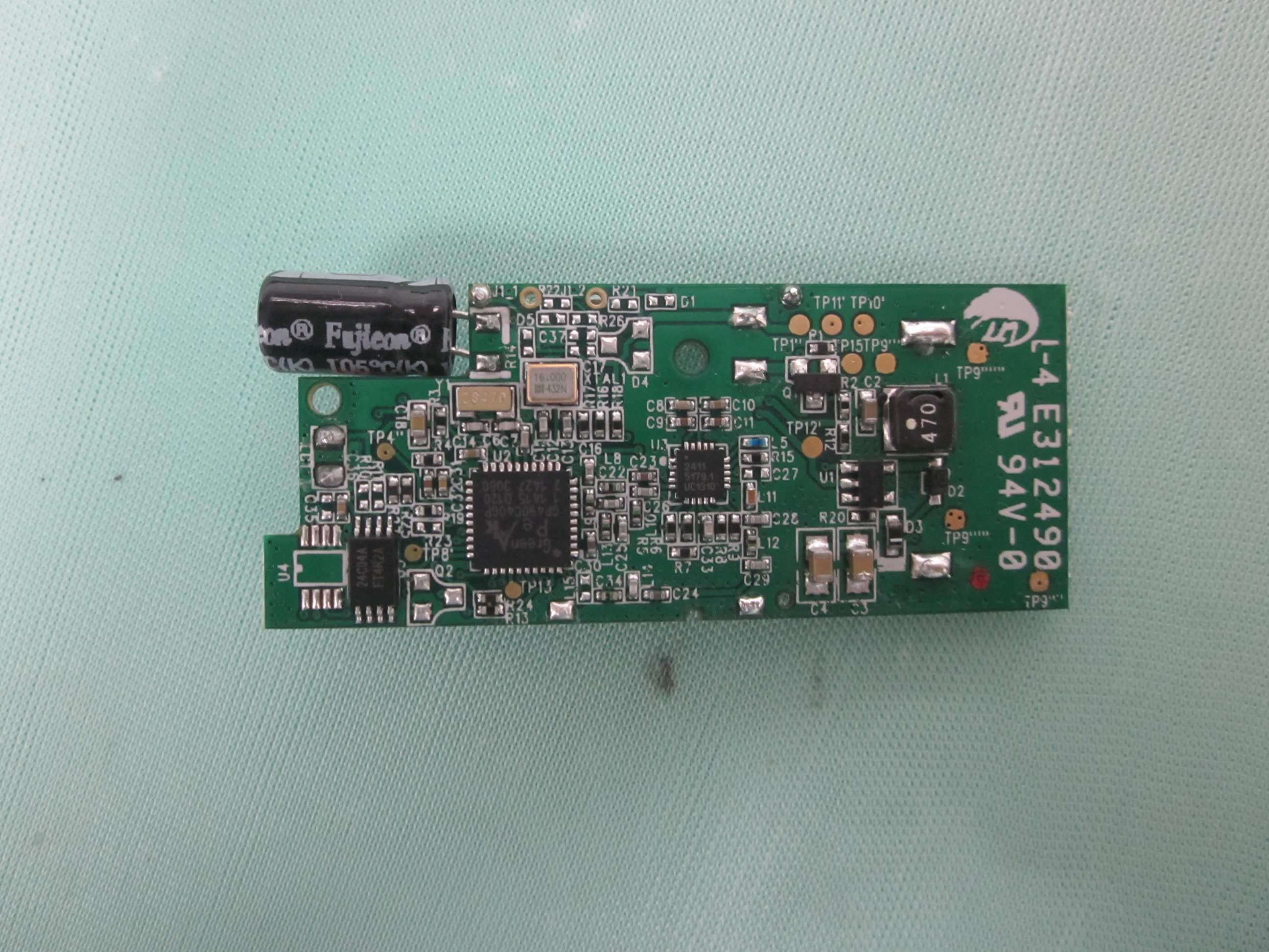
N9ZGRP002
Oct 22, 2015Door/Window Sensor
Equipment Class
DTS - Digital Transmission System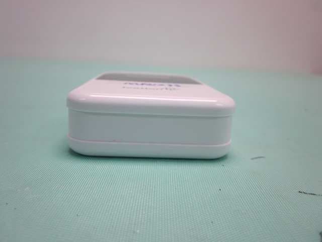
N9ZMAV233
Jul 02, 2015Wireless Kitchen Thermometer
Equipment Class
DSC - Part 15 Security/Remote Control Transmitter