N9Z882F01RF Wireless In/Out Thermo Clock
Ewig Industries Macao Commercial Offshore Limited
Click to zoom
Application Details
- Equipment Class
- CRR - Superregenerative Receiver
- Date of Grant
- May 17, 2006
- Application Purpose
- Original Equipment
- Date of Application
- May 17, 2006
- Equipment Note
- RF Wireless In/Out Thermo Clock
- Frequency Range
- 433.00000000 - 433.00000000
- Country
- Macau
Documents & Files
Document Text
Text extracted from the exhibit documents filed with the FCC. Open a document above to read the original.
Users Manual
3.BATTERY INSTALLATION – Very Important Note:The batteries must be installed in the following sequence in order to activate the outdoor temperature sensor. 1 st . Insert the batteries into the indoor receiving unit. 2 nd . Insert the batteries into the outdoor remote sensor. NOTE:When replacing the batteries, in the receiving unit, please repeat all steps in point 3. When replacing the batteries, in any of the remote sensor units (if more than 1), please refer to point 13. It is important to note that new batteries are always to be used. Do not mix old and new batteries as the old ones may leak. Furthermore, in order to protect our environment, please dispose the old batteries promptly and properly. Please do not burn or bury them. Set Up instructions for: For the receiving unit a.Press the cover tab, and slide down the battery compartment cover at the back of the receiving unit. b.Insert 2 AAA size batteries according to the polarity marks “+” and “-” shown in the battery compartment. c.The (OUT) icon and the dash (---) icon will flash at the bottom of the LCD display. The receiving unit is now ready to receive a signal from the RF remote sensor unit. For the remote sensor unit a.Remove the removable stand and wall-mount of the remote sensor unit by releasing the 2 fixing snaps at the bottom of the unit and pulling it so as to lift it off the sensor. b.Using a small Philips screwdriver, unscrew the 4 screws that allow the battery compartment cover to stay in place. c.Once the 4 screws are completely loosened, remove the cover. d.Insert 2 AAA size batteries according to the polarity marks shown in the battery compartment. e.Once the batteries are inserted in the battery compartment, the sensor will automatically transmit a temperature signal to the receiving unit at 30- second intervals. The sensor is also equipped with a manual transmission button (TX/HOLD RESET). If auto-registration is not successful, press this button for 2 seconds, the remote sensor will automatically send a temperature signal to the receiving unit. f.The temperature read by the remote sensor will appear at the bottom of the LCD display. If it does not, repeat all steps of point 3. BATTERY INSTALLATION. g.Once registration of the signal is confirmed, the icon “1” will appear in the upper left corner of the bottom part of the LCD. Reinstall the rubber seal into the cover groove, and close the battery cover. Tighten the screws, and snap on the removable stand and wall-mount. Note:After placing the remote sensor in its desired location, it may take up to 5 minutes for the receiving unit to display the temperature read by that particular remote. If the (---) dash icon appears and flashes, this indicates that the signal has been interrupted. In this case, rotate the sensor in steps of 45°, and wait at least 3 minutes at each step. If the (---) dash icon stops flashing, press and hold the [SNOOZE/LIGHT] button for 5 seconds so as to allow the receiving unit to re-register the temperature read by the remote. The (---) dash icon will flash again. If the receiving unit is still not registering after this proce dure, please move the remote closer to the receiving units or reposition both units until the receiving unit registers the remote sensor’s readings. For better results, the transmission range should not exceed 100 feet (30meters) in a relatively open space area. Do not confine either unit in a steel container or heavily insulated room. 4.ADDING ADDITIONAL REMOTE TEMPERATURE SENSORS (OPTIONAL) The 883F01 is designed to receive signals from a maximum 3 different remote temperature sensors. Following are some brief instructions for the basic setup of remote temperature sensor units with the 883F01. These extra sensors can be purchased by contacting Springfield Instruments Company of Canada directly at (514) 748-6721. Note: When setting up multiple units it is important to remove the batteries from all existing units in operation, then to insert batteries first into the receiving unit, and second into all the remote temperature sensor units in numeric sequence. Transmission problems will arise if this is not done correctly and if the total time for set-up exceeds 6 minutes. 1.It is necessary to remove the batteries from all units currently in operation. 2.Remove the battery covers of the receiving unit and all remote temperature sensor units. 3.Place all remote temperature sensor units in a numeric sequential order. 4.Insert batteries in the receiving unit as described in point 3. 5.In sequential order, install batteries in the remote sensor units as described in point 3. Please do not insert batteries in all remote sensors at the same time, otherwise this will cause unsuccessful registration. So, you must wait for the registration of the first remote to be completed (i.e. the temperature read by the first remote will be displayed at the bottom of the LCD and the icon “1” will appear indicating that the first remote has registered). Then insert the batteries in the second remote sensor, and wait for the registration to be completed (i.e. the temperature read by the second remote will be displayed at the bottom of the LCD and the icon “2” will appear indicating that the second remote has registered). If you have a third remote, only after the second remote has registered can you install the batteries in the third one, and wait for registering. If either one of the remotes fails to register, please repeat all steps of point 4. Note:After placing the remote sensors in their desired location, it may take up to 5 minutes for the receiving unit to display the temperature read by a particular remote. If the (---) dash icon appears and flashes for a particular remote, this indicates that the signal has been interrupted. In this case, rotate the sensor in steps of 45°, and wait at least 3 minutes at each step. If the (---) dash icon stops flashing, press and hold the [SNOOZE/LIGHT] button for 5 seconds so as to allow the receiving …
Text truncated - open the document above for the full version.
Block Diagram
MODEL:882F01 BLOCK DIAGRAM LCD DISPLAY CPU SPL081A KEY BOARD CRYSTAL 32768Hz OSCILLATOR BUZZER ALARM 1.5 V Zener Circuit Amplifier O 3.0V BATTERY SUPPLY Low Voltage Detector Temperature Sensor
External Photos
Test Setup FCC ID : N9Z882F01 External Photo - Front External Photo - Rear
ID Label/Location Info
Silkscre en color in PMS 426C THERMOMETER882F01 F C C I D : N 9 Z 8 8 2 F 0 1 Silkscre en color in PMS 426C THERMOMETER882F01 F C C I D : N 9 Z 8 8 2 F 0 1 Silkscre en color in PMS 426C THERMOMETER882F01 F C C I D : N 9 Z 8 8 2 F 0 1 Silkscre en color in PMS 426C THERMOMETER882F01 F C C I D : N 9 Z 8 8 2 F 0 1
Internal Photos
Test Setup FCC ID : N9Z882F01 Internal Photo - 1 Internal Photo - 2 Test Setup FCC ID : N9Z882F01 Internal Photo - 3 Internal Photo - 4 Test Setup FCC ID : N9Z882F01 Internal Photo - 5
Operational Description
Circuit Description RF Receiver Section : Transistor Q9 functions as an RF pre-amplifier and Q10 forms the major part of the conventional super regenerative detector stage. The detected output is input to the LM324 operational amplifier with the first stage extracting the data from the very weak signal. Its second stage operational amplifier provides gain to the extracted data. The last stage purely compares the amplified data and makes the weak signal data to be square ware in order to let the MCU recognize the data easily. 1.5V Zener Circuit: Transistor Q5 and Q7 combine together to form the a DC regulator. Q5 is the pass transistor to delivery enough power to the MCU while Q7 samples the Q5’s emitter voltage and stabilizes the Q5’s base voltage in order to keep the Q5 emitter output voltage to be fairly constant. Thus the power supply voltage of the MCU becomes 1.5V and suitable for the MCU to function properly. Low voltage detector: Transistor Q1, D2,R7,R50 and R6 are combined together to form the low battery detector. Since the minimum operating voltage of the RF receiver is 2.65V, we have to set the low voltage detector to be activated before 2.65V and our design have set this value between 2.85V and 2.65V. In this circuit section, R7 and R50 provide an unconventional (but precise) resistance value and combine with R6 to make a voltage divider to the battery voltage after the voltage drop due to the silicon PN junction threshold voltage of the diode D2. Thus at a voltage slightly lower than 2.85V, Q1 is being cut off and a zero voltage is then input to the low-battery detection input of the MCU in order to switch on the Low-Battery icon on the LCD display. Temperature Sensor: This temperature sensor circuit section is achieved by the charging the C5 through R5 as the reference time constant and R1,Th and R3 form the temperature dependent charging path to C5. These two charging paths can then form two different time interval and thus the MCU can calculate the difference to convert it into temperature value. The reason why we need a reference charging path is for eliminating the temperature effect of this circuit components especially the capacitor C5.
Test Report
• The test results reported in this test report shall refer only to the sample actually tested and shall not refer or be deemed to refer to bulk from which such a sample may be said to have been obtained. • This report shall not be reproduced except in full without prior authorization from Intertek Testing Services Hong Kong Limited. • For Terms And Conditions of the services, it can be provided upon request. • The evaluation data of the report will be kept for 3 years from the date of issuance. Intertek Testing Services Hong Kong Ltd. 2/F., Garment Centre, 576 Castle Peak Road, Kowloon, Hong Kong. Tel: (852) 2173 8888 Fax: (852) 2371 0521 Website: www.hk.intertek-etlsemko.com Ewig Industries Macao Commercial Offshore Ltd. Application For Certification (FCC ID: N9Z882F01) Superregenerative Receiver 0526626 DL/ Sandy Lee January 16, 2006 INTERTEK TESTING SERVICES FCC ID: N9Z882F01 i LIST OF EXHIBITS INTRODUCTION EXHIBIT 1: General Description EXHIBIT 2: System Test Configuration EXHIBIT 3: Emission Results EXHIBIT 4: Equipment Photographs EXHIBIT 5: Product Labelling EXHIBIT 6: Technical Specifications EXHIBIT 7: Instruction Manual EXHIBIT 8: Miscellaneous Information INTERTEK TESTING SERVICES FCC ID: N9Z882F01 ii MEASUREMENT/TECHNICAL REPORT Ewig Industries Macao Commercial Offshore Ltd. - MODEL: 882F01 FCC ID: N9Z882F01 This report concerns (check one:) Original Grant X Class II Change _____ Equipment Type: Superregenerative Receiver (example: computer, printer, modem, etc.) Deferred grant requested per 47 CFR 0.457(d)(1)(ii)? Yes No X If yes, defer until: date Company Name agrees to notify the Commission by: date of the intended date of announcement of the product so that the grant can be issued on that date. Transition Rules Request per 15.37? Yes No X If no, assumed Part 15, Subpart B for unintentional radiator - the new 47 CFR [10-01-04 Edition] provision. Report prepared by: Derek Leung Intertek Testing Services Hong Kong Ltd. 2/F., Garment Centre, 576, Castle Peak Road, Kowloon, Hong Kong. Phone: 852-2173-8539 Fax: 852-2371-0521 INTERTEK TESTING SERVICES FCC ID: N9Z882F01 iii Table of Contents 1.0 General Description .......................................................................................... 2 1.1 Product Description ............................................................................................. 2 1.2 Related Submittal(s) Grants ................................................................................ 2 1.3 Test Methodology................................................................................................ 3 1.4 Test Facility ......................................................................................................... 3 2.0 System Test Configuration ............................................................................... 5 2.1 Justification ......................................................................................................... 5 2.2 EUT Exercising Software .................................................................................... 5 2.3 Special Accessories ............................................................................................ 5 2.4 Equipment Modification ....................................................................................... 6 2.5 Measurement Uncertainty ................................................................................... 6 2.6 Support Equipment List and Description ............................................................. 6 3.0 Emission Results .............................................................................................. 8 3.1 Field Strength Calculation ................................................................................... 9 3.2 Radiated Emission Configuration Photograph ................................................... 10 3.3 Radiated Emission Data.................................................................................... 11 4.0 Equipment Photographs ................................................................................. 14 5.0 Product Labelling ............................................................................................ 16 6.0 Technical Specifications ................................................................................ 18 7.0 Instruction Manual .......................................................................................... 20 8.0 Miscellaneous Information ............................................................................. 22 8.1 Stabilization Waveform...................................................................................... 23 8.2 Discussion of Pulse Desensitization .................................................................. 24 8.3 Calculation of Average Factor ........................................................................... 25 8.4 Emissions Test Procedures............................................................................... 26 INTERTEK TESTING SERVICES FCC ID: N9Z882F01 iv List of attached file Exhibit type File Description filename Test Report Test Report report.pdf Operation Description Technical Description descri.pdf Test Setup Photo Radiated Emission radiated photos.doc External Photo External Photo external photos.doc Internal Photo Internal Photo internal photos.doc Block Diagram Block Diagram block.pdf Schematics Circuit Diagram circuit.pdf ID Label/Location Label Artwork and Location label.pdf User Manual User Manual manual.pdf Test Report Stabilization Waveform superreg.pdf INTERTEK TESTING SERVICES FCC ID: N9Z882F01 1 EXHIBIT 1 GENERAL DESCRIPTION INTERTEK TESTING SERVICES FCC ID: N9Z882F01 2 1.0 General Description 1.1 Product Description The Equipment Under Test (EUT) is a Receiver operating at 433MHz. The EUT is powered by 3V d.c. (2 x 1.5V “AAA” battery). It receives temperature signal from remote sensor and displays the reading on the unit. Also, it has internal sensor to mea…
Text truncated - open the document above for the full version.
Test Setup Photos
Test Setup FCC ID : N9Z882F01 Radiated Photo - Front Radiated Photo - Rear RADIATED Model: 882F01 Job No.: 0526626 RADIATED Model: 882F01 Job No.: 0526626
Contact Information
Applicant
Liu Binkky(Electronic Supervisor)
Technical Contact
Intertek Testing Services Hong Kong Ltd.Derek Leung
[email protected]852-2173-8539
2/F., Garment Centre, · Kowloon · Hong Kong
Non-Technical Contact
Intertek Testing Services Hong Kong Ltd.Derek Leung
[email protected]852-2173-8539
Test Firm
Intertek Testing Services Hong KongBilly Chow
Technical Specifications
| # | Rule Parts | Frequency Range | Power Output |
|---|---|---|---|
| 1 | 15B | 433 MHz - 433 MHz | - |
Other Applications from Ewig Industries Macao Commercial Offshore Limited
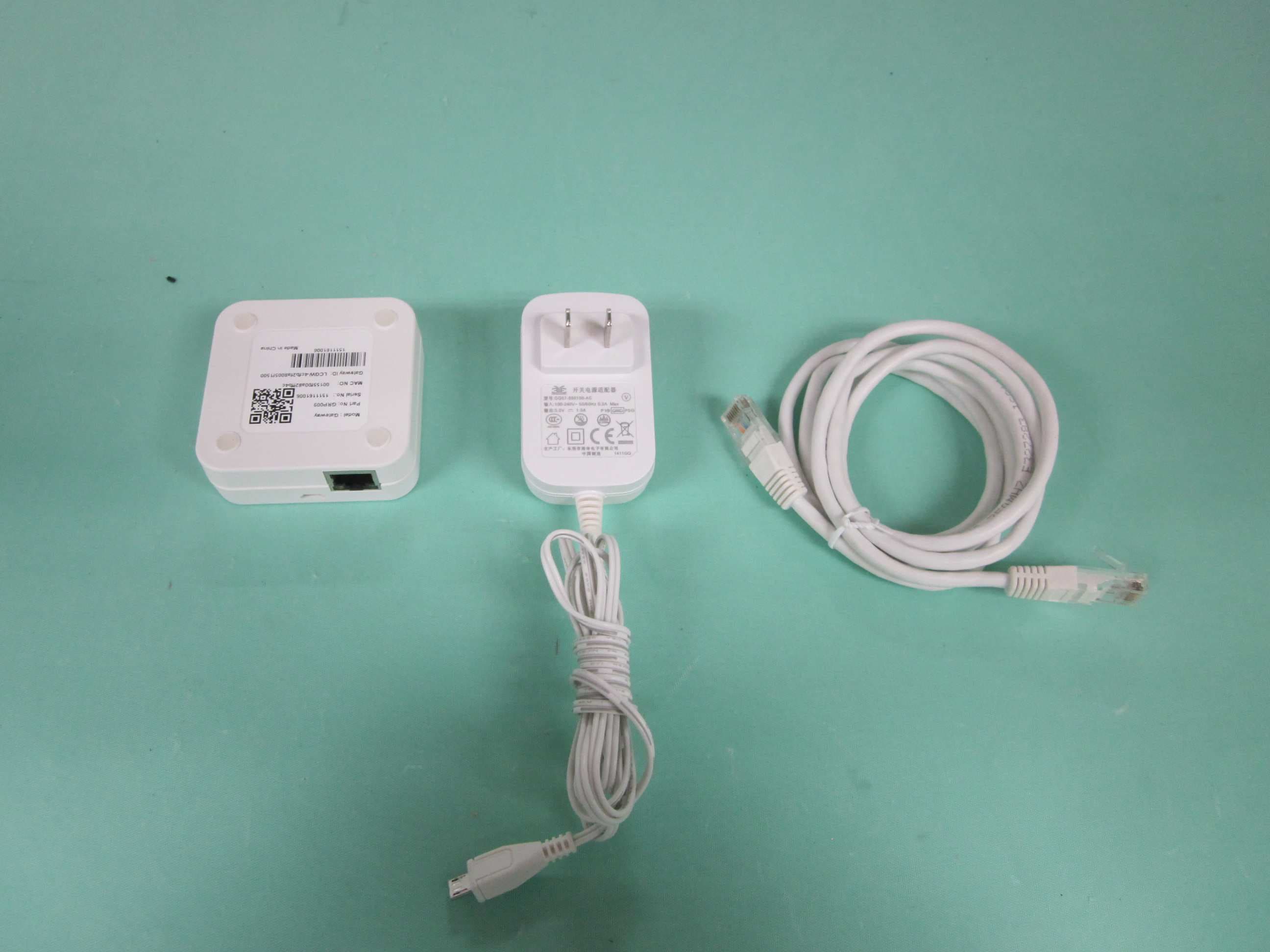
N9ZGRP009
Dec 22, 2015Gateway
Equipment Class
DTS - Digital Transmission System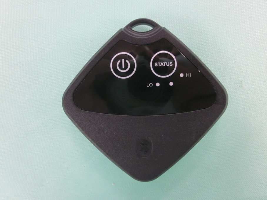
N9ZTLG002
Dec 03, 2015Temperature Logger
Equipment Class
DTS - Digital Transmission System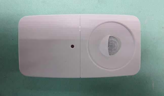
N9ZGRP001
Oct 22, 2015PIR Sensor
Equipment Class
DTS - Digital Transmission System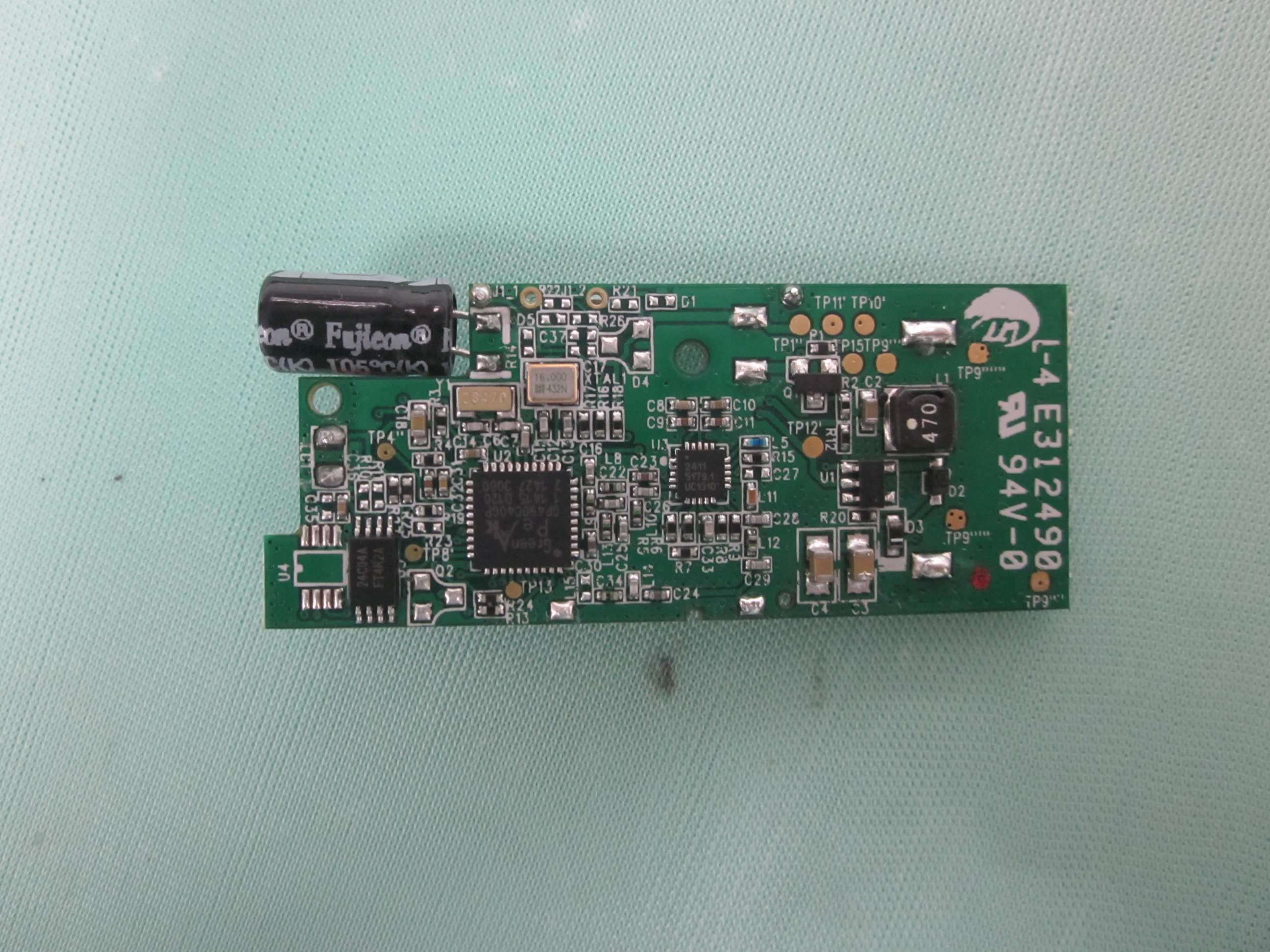
N9ZGRP002
Oct 22, 2015Door/Window Sensor
Equipment Class
DTS - Digital Transmission System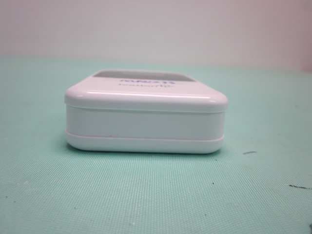
N9ZMAV233
Jul 02, 2015Wireless Kitchen Thermometer
Equipment Class
DSC - Part 15 Security/Remote Control Transmitter