N9ZTTX302RF Wireless Transmitter/Long Range Thermo Sensor
Ewig Industries Macao Commercial Offshore Limited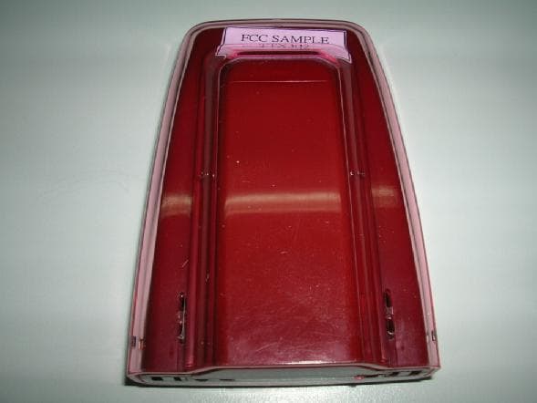
Click to zoom
Application Details
- Equipment Class
- DSC - Part 15 Security/Remote Control Transmitter
- Date of Grant
- Mar 28, 2007
- Application Purpose
- Original Equipment
- Date of Application
- Mar 28, 2007
- Equipment Note
- RF Wireless Transmitter/Long Range Thermo Sensor
- Frequency Range
- 433.90000000 - 433.90000000
- Country
- Macau
Documents & Files
Document Text
Text extracted from the exhibit documents filed with the FCC. Open a document above to read the original.
Users Manual
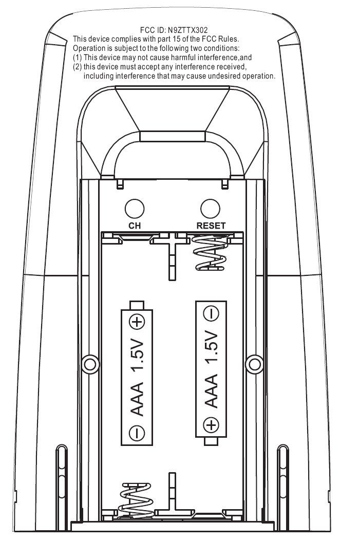
Thermo sensor Model: TTX302 Instruction Manual Congratulations on your of purchasing our new long range outdoor thermo senor which can cover up to 75m range in an open area. This sensor is designed for everyday use for the home or office and used to monitor the temperature change of outdoor sites. Features A. LED indicator Flashes when remote unit transmits a reading. B. Channel number Indicates the remote sensor is set to which channel and the user can find the corresponding reading in the same channel in the linked receiving unit. C. Temperature display Displays the measured temperature. Description of buttons The remote sensor has 3 function buttons inside the battery compartment 1. [CH] button After the battery installation, the LED blinks slowly every 1.5 seconds and channel number shows ‘1’ to indicate it is now under channel setting mode and is set to channel 1 by default. If the user presses no key within ten seconds, the unit will auto-exit the channel setting. If the user press [CH] button once during the channel setting, the channel number A B C is changed to ‘2’ to indicate the unit is set to channel 2. If the user press [CH] button again, the channel number will be advanced to channel ‘3’ and so on. The maximum channel number is ‘5’ and the unit will be scrolled back to channel ‘1’ at the 5 th press of the [CH] button. 2. [C/F] button Press to toggle unit °C or °F 3. [ RESET ] Button Press to hardware reset the unit to factory setting Setting procedure to link up with a receiving unit This device is designed for easy set up with no wire installation. The following steps are required to be done in proper sequence to link up with a receiving unit. Please insert batteries for the receiving unit before doing so for the remote unit. 1. Remove the bracket stand. 2. Unlock two latches in the bottom to release the semi-transparent jacket. 3. Slide down the battery door in the back. 4. Insert 2 pieces AAA size batteries according to polarity marking on the battery compartment. 5. The LED blinks slowly to indicate it is under the channel setting mode and the user can set it to other channel by press [CH] key. 6. The temperature of the sensor will appear on the selected channel of the receiving unit if it is linked up with the receiving unit successfully. 7. Close the battery door and use two latches in the bottom to lock it with the semi-transparent jacket. Follow the same procedure (1 to 7) to register other remote sensors. Note: For the user purchasing more than one remote sensor, he must set the sensors to different channel in the start up to avoid conflicts. Precautions a. Do not clean the unit with abrasive or corrosive compound. It may scratch the plastic parts and corrode the electronic circuits. b. Do not subject the unit to excessive force shock, dust, temperature or humidity, which may result in malfunctioning, shorter electronic life span, damaged battery and distorted parts. c. Do not tamper with these units’ internal components. Doing so will invalidate the warranty on the unit and may cause unnecessary damage battery and distorted parts. d. Do not subject the unit to excessive exposure to direct sunlight. The remote sensor is splash proof. Never immerse it in water or expose to heavy rain. e. Always read the users manual thoroughly before operating the unit. Specification Displayed range : -20.0°C to +60.0°C (-4.0°F to 140.0°F) Proposed operating range : -10.0°C to +50.0°C (14.0°F to 122.0°F) Temperature resolution : 0.1°C (0.1°F) RF Transmission Frequency : 433 MHz RF Transmission Range : Maximum 75 meters Temperature sensing cycle : 60 - 75 seconds Batteries : Use 2 pieces UM-4 AAA size 1.5V alkaline battery Information to user NOTE: THE MANUFACTURER IS NOT RESPONSIBLE FOR ANY RADIO OR TV INTERFERENCE CAUSED BY UNAUTHORIZED MODIFICATIONS TO THIS EQUIPMENT. SUCH MODIFICATIONS COULD VOID THE USER AUTHORITY TO OPERATE THE EQUIPMENT Note: This equipment has been tested and found to comply with the limits for a Class B digital device, pursuant to part 15 of the FCC Rules. These limits are designed to provide reasonable protection against harmful interference in a residential installation. This equipment generates, uses and can radiate radio frequency energy and, if not installed and used in accordance with the instructions, may cause harmful interference to radio communications. However, there is no guarantee that interference will not occur in a particular installation. If this equipment does cause harmful interference to radio or television reception, which can be determined by turning the equipment off and on, the user is encouraged to try to correct the interference by one or more of the following measures: --Reorient or relocate the receiving antenna. --Increase the separation between the equipment and receiver. --Connect the equipment into an outlet on a circuit different from that to which the receiver is connected. --Consult the dealer or an experienced radio/TV technician for help.
External Photos
PHOTOGRAPH OF THE PRODUCT FRONT VIEW OF THE PRODUCT REAR VIEW OF THE PRODUCT
Internal Photos
PHOTOGRAPH OF THE PRODUCT INNER CIRCUIT TOP VIEW INNER CIRCUIT BOTTOM VIEW
Operational Description
FCC ID: N9ZTTX302 Circuit Description The 433.9 MHz crystal oscillator drives the base of Q2 the final/buffer amplifier. The modulation provided by IC. The output of Q2 has the matching network consisting of L3, L4, L5 and C17, C18 that limit the harmonic content and effect the proper coupling of the antenna to the output stage. Antenna, Ground and Power Source There is no external ground connection. The ground is only that of the printed circuit board. Electric current is supplied by a 3 Volt (“AAA” size battery x 2) primary battery Operation Descriptions The transmitter is a thermometer operating at 433.9MHz band. The transmitter is powered by a 3V battery (“AAA” size battery x2) and the transmitting frequency is crystal controlled. The operation is achieved by different combinations of form pulse modulating signal on the 433.9MHz carrier frequency. Remarks: It is Pulse transmitter, Modulation by IC; and type is Pulse modulation.
Test Setup Photos
TEST SET UP PHOTOGRAPH OF THE PRODUCT MEASUREMENT OF RADIATED EMISSION TEST SET UP
Contact Information
Applicant
Liu Binkky(Electronic Supervisor)
Test Firm
Hong Kong Standards and Testing CenterWison Wong
Technical Specifications
| # | Rule Parts | Frequency Range | Power Output |
|---|---|---|---|
| 1 | 15.231(e) | 433.9 MHz - 433.9 MHz | - |
Other Applications from Ewig Industries Macao Commercial Offshore Limited
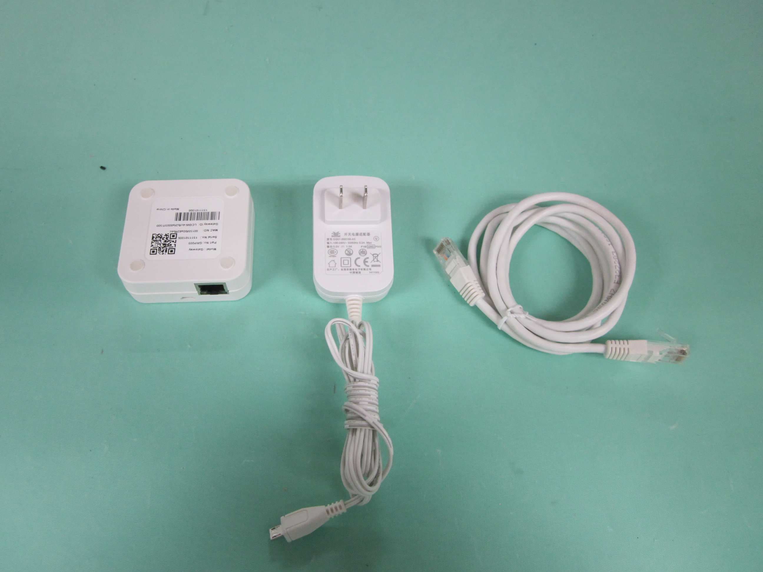
N9ZGRP009
Dec 22, 2015Gateway
Equipment Class
DTS - Digital Transmission System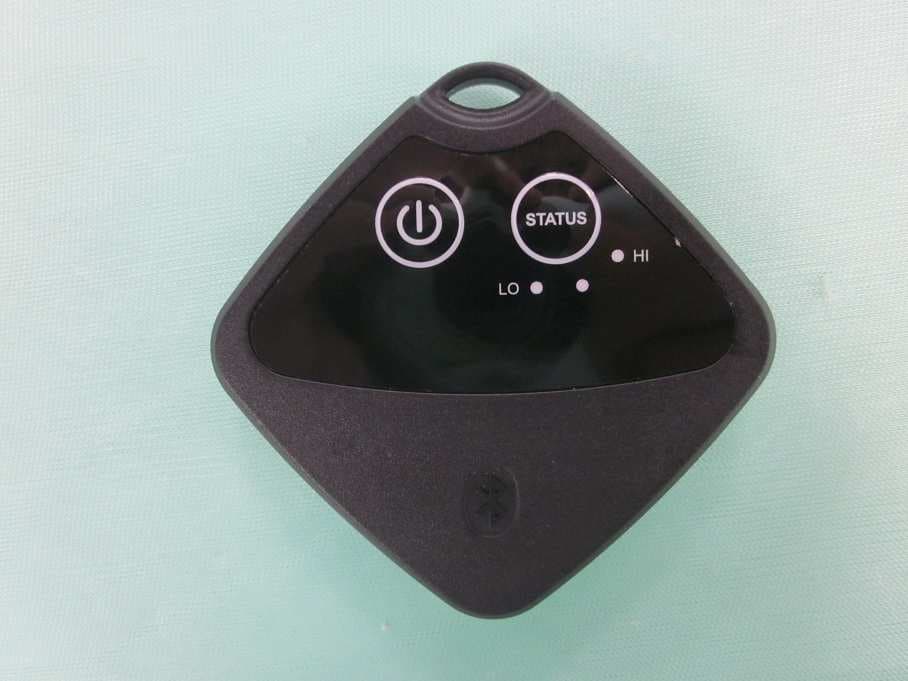
N9ZTLG002
Dec 03, 2015Temperature Logger
Equipment Class
DTS - Digital Transmission System
N9ZGRP001
Oct 22, 2015PIR Sensor
Equipment Class
DTS - Digital Transmission System
N9ZGRP002
Oct 22, 2015Door/Window Sensor
Equipment Class
DTS - Digital Transmission System
N9ZMAV233
Jul 02, 2015Wireless Kitchen Thermometer
Equipment Class
DSC - Part 15 Security/Remote Control Transmitter