NBF-PT9130Mobile Computer
Argox Information Co Ltd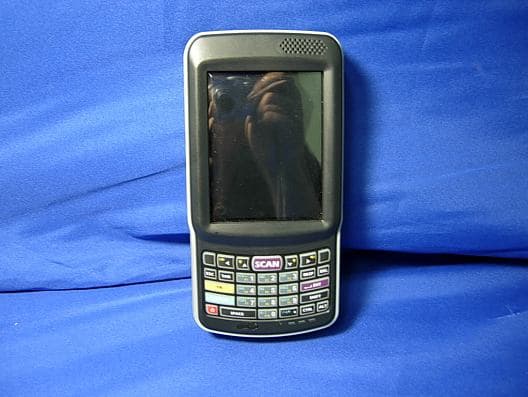
Click to zoom
Application Details
- Equipment Class
- DSS - Part 15 Spread Spectrum Transmitter
- Date of Grant
- Sep 16, 2010
- Application Purpose
- Original Equipment
- Date of Application
- Sep 03, 2010
- Equipment Note
- Mobile Computer
- Frequency Range
- 2402.00000000 - 2480.00000000
- Company
- Argox Information Co Ltd
- Country
- Taiwan
Documents & Files
Document Text
Text extracted from the exhibit documents filed with the FCC. Open a document above to read the original.
Users Manual
User’s Manual PT-9XXX-X-X Mobile Computer (WinCE 6.0 version) DOC NO. UM-P9005-01 Mar . 2010 Version 1.0 Empower the Bar Code User’s Manual II NOTICE: This user’s manual may be revised or withdrawn at any time without prior notice. Copyright 2009, Argox Information Co., Ltd. All rights reserved. This manual may not, in whole or in part, be copied, photocopied, reproduced, translated or converted to any electronic or machine readable form without the prior written consent of Argox. Limited warranty and disclaimers By opening the package of this product you agree to become bound by the liability and warranty conditions as described below. Under all circumstances this manual should be read attentively before installing and or using the product. In no event, will Argox be liable for any direct, indirect, consequential or incidental damages arising out of use or inability to use both the hardware and software, even if Argox has been informed about the possibility of such damages. A serial number appears on all Argox products. This official registration number is strictly related to the device purchased. Make sure that the serial number appearing on your Argox device has not been removed. Servicing by our service department can only be carried out under warranty. All Argox products are warranted for the legal warranty period after purchase, covering defects in material and workmanship. Argox will repair or, at its opinion, replace products that prove to be defective in material or workmanship under proper use during the warranty period. Argox will not be liable in case modifications are made by the customer. In such case the standard repair charge will be applicable. The standard charge for repair will also be applicable in case no defect is found at all. These rules also apply for products that are still under warranty. Therefore, you are advised to have the product specifications always at hand. Trademarks used are property of their respective owners. User’s Manual I Table of Contents 1. INTRODUCTION........................................................................................................1 1.1 ABOUT THIS MANUAL............................................................................................1 1.2 USER AND PRODUCT SAFETY.................................................................................2 1.3 SPECIFICATIONS....................................................................................................4 2. GETTING STARTED..................................................................................................6 2.1 CHECK THE PACKAGE............................................................................................6 2.1.1 Compact Package........................................................................................6 2.1.2 Cadle & Pistol grip Package (Optional)......................................................7 2.2 DETAILED VIEW.....................................................................................................8 2.2.1 PT-90 Mobile Computer..............................................................................8 2.2.2 Cradle.........................................................................................................9 2.3 INSTALLING, REPLACING AND CHARGING BATTERIES........................................10 2.3.1 Installing / Replacing the Battery Pack......................................................12 2.3.2 Charging the Battery Pack with a Power Adapter......................................12 2.3.3 Charging the Battery Pack with Cradle......................................................13 2.4 INSTALLING IN A SYSTEM.....................................................................................14 2.4.1 Via USB /RS-232 Cable.............................................................................14 2.4.2 Via CRD-90 Cradle...................................................................................14 3. OPERATION OF THE MOBILE COMPUTER.......................................................15 3.1 KEYPAD DESCRIPTION.........................................................................................15 3.2 FUNCTION KEY DESCRIPTION..............................................................................16 3.3 INSTALL MICRO SD CARD INTO PT-90.................................................................17 3.4 CONFIGURING PT-90 SETTINGS...........................................................................18 3.4.1 Calibrating Touch Screen Alignment.........................................................18 3.4.2 Adjusting Brightness..................................................................................19 3.4.3 Muting Sound............................................................................................19 3.4.4 Using the Stylus.........................................................................................19 3.5 ENTERING INFORMATION....................................................................................20 3.5.1 Entering Information Using a Keypad........................................................20 3.5.2 Entering Information Using the Keyboard Input Panel...............................20 3.5.3 Entering Data via the Bar Code Scanner...................................................20 3.6 POWER MANAGEMENT........................................................................................21 3.6.1 Power Status Indication.............................................................................21 3.6.2 Saving Battery Power................................................................................23 3.6.3 Suspend Mode...........................................................................................24 3.6.4 Resume.....................................................................................................25 3.7 RESETTING THE PT-90..................................................................…
Text truncated - open the document above for the full version.
Users Manual
User’s Manual 37 Figure 4-3 Scan Configuration-3 After you change settings, press the OK button to configure, or press Restore Default to return to the scan default settings. 4.2 Scan driver Scan driver lets you put data into Microsoft Wordpad. Open scan driver and the scan module powers on the scanner. You can then scan barcode. To turn off the power, press Exit on the task bar. Figure 4-4 Scan Driver User’s Manual 38 4.3 Scan test The PT-90 has a Scan Test.exe program that allows you to test the barcode scan function. Scan Test.exe is located in directory Desktop→Utility→Scan Test.exe. This program shows barcode type and barcode data when pressing the Scan key. Figure 4-5 Scan Test 4.4 Reading barcode Note: Observe handling precautions. Make sure the mobile computer is installed according to instructions. Never remove the main batteries or battery pack while the mobile computer is turned on. Doing so can cause loss of data in the mobile computer. Avoid looking directly into the LED light beam emitter, or pointing the LED light beam directly into someone’s eyes. Position the LED light beam over the bar code from margin to margin and pass the scanner downward over the bar code, as shown in the scan position illustration Good read scan position Incorrect read scan positions User’s Manual 39 The scanning sequence is defined by the user’s application. A typical sequence is: Point the mobile computer at the barcode and press the Trigger key . Point the LED lightbeam at barcode as shown in the scan position illustration above. The scanner reads the barcode and the results are indicated. A “Good Read” means that the scanner has effectively recognized and decoded the bar code. In most cases, the application program provides an indicator signal to indicate a good read. If the read is incorrect, try again paying close attention to the instructions. When reading a small bar code, decrease the distance between the mobile computer and the bar code. For larger bar codes, position the mobile computer so that the bar code fits into the LED light beam. When reading a very high density bar code, decrease the distance between the mobile computer and the bar code. For a low density bar code, increase the distance between the mobile computer and the bar code. 4.5 Barcode reading problems When the barcode can NOT be read, try the following: Change the angle between the bar code and the mobile computer. Change the distance between the bar code and the mobile computer. If the bar code is larger than the LED light beam, try moving the mobile computer a bit further away from the bar code. User’s Manual 40 5. Utilities 5.1 Function Key Setting To assign your favorite application program or virtual key from F1 ~ F10 and P1~P4 hot keys. Function Key.exe is located in directory Desktop→Utility→Function_Key.exe. 1. Choose F1~F10 or P1~P4 from list. 2. Tap Define to define application or virtual key. 3. Tap Apply or OK to set function key setting. 4. Tap the Default to return to default setting. Figure 5-1 Function Key Setting Figure 5-2 Function Key Define User’s Manual 41 5.2 Timeout & Brightness Timeout&Brightness setting is a tool for changing the LCD backlight and keypad LED. If you wish to save power use this program to change LCD backlight and keypad LED settings. This application supports battery power and external power settings. Figure 5-3 Timeout & Brightness User’s Manual 42 6. Software Applications The PT-90 includes software applications such as Internet Explorer, Media player, Microsoft WordPad, Remote Desktop Connection, Transcriber, and Windows Explorer. Figure 6-1 Software Applications 6.1 Internet Explorer With Internet Explorer, you can view Web or intranet Web pages on your device. You will need to use WLAN to connect to an Internet server provider (ISP) or network. Figure 6-2 Internet Explorer 6.2 Media Player The PT-90 comes with Media Player for Windows CE installed. Open Media Player by selecting Start → Programs →Media Player from the desktop. Select File → Open to open a new media file. Please refer to www.microsoft.com for additional information and help with your Microsoft Windows Media Player. Figure 6-3 Media Player User’s Manual 43 6.3 Microsoft WordPad You can create and edit documents and templates in WordPad, using buttons and menu commands that are similar to those used in the desktop version of Microsoft Word. You can work with files Normal or Outline view. WordPad documents are usually saved as .pwd files, but you can also save documents in other file formats, such as .rtf or .doc. Figure 6-4 Microsoft Wordpad 6.4 Remote Desktop Connection Using Remote Desktop Connection, you can log on to Windows Mobile computer Server and use all programs installed on this server. For example, instead of running Microsoft Pocket Word, you can run the desktop version of Microsoft Word. Figure 6-5 Remote Desktop Connection 6.5 Transcriber Features: Microsoft Transcriber is the natural handwriting recognition solution for your Windows CE device. It recognizes words from its integrated dictionary, and allows you to write in cursive, print or mixed handwriting. The letter Shapes Selector (note 1) is for optimizing recognition to your own handwriting style Transcriber works transparently in the background of all Windows CE applications providing handwriting input, while taking away no precious screen space. Figure 6-6 Transcriber User’s Manual 44 6.6 Windows Explorer Windows Explorer works almost the same on your PDA as it does on your PC. See the topics below for information about the difference in Windows Explorer on your device. Figure 6-7 Windows Explorer User’s Manual 45 7. Communication Argox PT-90 lets you link to a host computer via RS-232 or USB port for data communication. This chapter gives an overview of PT-90’s communication capabilities.(remove) The Argox PT-90 lets you link to a host computer via RS-232 or USB port for data communication with cable or cra…
Text truncated - open the document above for the full version.
Attestation Statements
Argox Information CO.,Ltd. 7F,NO.126,Lane 235,Pao-Chiao Rd., Hsin Tien , Taipei, Taiwan Tel: 886-89124000 FAX: 886-89126322 Data: Sep.07, 2010 Below are symbol index for multi listing of model number. Model: PT-9XXX-X-X = PT-9ABC-D-E “A” can be 0, 1, 2 or 3 for Scan engine type. 0: CCD, 1: Laser, 2: 2D imager, 3: CCD -Liner stacked “B” can be 0, 1, 2 or 3 for communication type. 0: Batch, 1: BT, 2: 802.11b/g, 3: BT & WIFI “C” can be 0, 1, 2 or 3 for accessory type. 0: N/A, 1: with gun “D” can be 0 or 1 for TEL – Edge. 0: N/A “E” can be 0 or 1 for TEL – GPS. 0: N/A, 1: GPS Sincerely, Gordon Hsu 7F,NO.126,Lane 235,Pao-Chiao Rd., Hsin Tien , Taipei, Taiwan Argox Information CO.,Ltd.
External Photos
Report No.: 101427R-RFUSP43V01 Page : 1 of 12 Attachment 2 : EUT Detailed Photographs (1) EUT Photo (2) EUT Photo Report No.: 101427R-RFUSP43V01 Page : 2 of 12 (3) EUT Photo (4) EUT Photo Report No.: 101427R-RFUSP43V01 Page : 3 of 12 (5) EUT Photo (6) EUT Photo
ID Label/Location Info
Argox Information Co.,Ltd. FCC ID.: NBF-PT9130 7F,NO.126,Lane 235,Pao-Chiao Rd., Hsin Tien , Taipei, Taiwan.Tel : 886-2-8912-1121 FCC ID Label The FCC ID and DoC Label will be placed on the equipment as shown in the photograph below.
ID Label/Location Info
Argox Information Co.,Ltd. FCC ID.: NBF-PT9130 7F,NO.126,Lane 235,Pao-Chiao Rd., Hsin Tien , Taipei, Taiwan.Tel : 886-2-8912-1121 FCC ID Label The FCC ID and DoC Label will be placed on the equipment as shown in the photograph below.
Internal Photos
Report No.: 101427R-RFUSP43V01 Page : 4 of 12 (7) EUT Photo (8) EUT Photo Report No.: 101427R-RFUSP43V01 Page : 5 of 12 (9) EUT Photo (10) EUT Photo Report No.: 101427R-RFUSP43V01 Page : 6 of 12 (11) EUT Photo (12) EUT Photo WLAN Module Report No.: 101427R-RFUSP43V01 Page : 7 of 12 (13) EUT Photo (14) EUT Photo WLAN Antenna Report No.: 101427R-RFUSP43V01 Page : 8 of 12 (15) EUT Photo (16) EUT Photo Bluetooth Module Report No.: 101427R-RFUSP43V01 Page : 9 of 12 (17) EUT Photo (18) EUT Photo Report No.: 101427R-RFUSP43V01 Page : 10 of 12 (19) EUT Photo (20) EUT Photo Bluetooth Antenna Report No.: 101427R-RFUSP43V01 Page : 11 of 12 (21) EUT Photo (22) EUT Photo Report No.: 101427R-RFUSP43V01 Page : 12 of 12 (23) EUT Photo 6cm WLAN Antenna Bluetooth Antenna
Operational Description
Report No. 101427R-RFUSP43V01 Page: 7 of 72 1.2. Operational Description The EUT is a Mobile Computer with built-in 2.4GHz Bluetooth V2.1+EDR transceiver. The number of the channels is 79 in 2402-2480MHz. The device adapts the frequency hopping spread spectrum modulation. The antenna is chip antenna and provides diversity function to improve the receiving function. The system receivers have input bandwidths that match the hopping channel bandwidths of their corresponding transmitters and shift frequencies in synchronization with the transmitted signals Frequency hopping spread spectrum systems are not required to employ all available hopping channels during each transmission. The transmitter is presented with a continuous data stream. In addition, a system employing short transmission bursts must comply with the definition of a frequency hopping system and must distribute its 79 channels and over the minimum number of hopping channels (75 channels). The incorporation of intelligence within a frequency hopping spread spectrum system that permits the system to recognize other users within the spectrum band so that it individually and independently chooses and adapts its hopsets to avoid hopping on occupied channels is permitted. The coordination of frequency hopping systems in any other manner for the express purpose of avoiding the simultaneous occupancy of individual hopping frequencies by multiple transmitters is not permitted.
RF Exposure Info
RF Exposure Statement 1. Standard Applicable According to 1.1307 (b)(1), systems operating under the provisions of this section shall be operated in a manner that ensure that the public is not exposed to radio frequency energy level in excess of the Commission’s guideline. This is a portable device. 2. Measurement Result: This a portable device and the max peak output power is 4.21 dBm = (.0026 W). The Max. Antenna Gain is 4.1 dBi. Therefore, the EIRP = 8.31 dBm (6.77mW), which lower than the threshold of 60/f GHz mW = (24.19 mW) The SAR/MPE measurement is not necessary. The device have include WLAN and Bluetooth function but WLAN antenna separation Bluetooth antenna more than 5cm. Refer to KDB 648474 there are no SAR collation requirement.
Test Report
Report No. 101427R-RFUSP43V01 Page: 1 of 72 Test Report Product Name Mobile Computer Model No. PT-9XXX-X-X (X=0~9,A~Z) FCC ID. NBF-PT9130 Applicant Argox Information Co.,Ltd. Address 7F,NO.126,Lane 235,Pao-Chiao Rd., Hsin Tien , Taipei, Taiwan Date of Receipt Jan. 25, 2010 Issued Date July 20, 2010 Report No. 101427R-RFUSP43V01 Report Version V1.0 The Test Results relate only to the samples tested. The test report shall not be reproduced except in full without the written approval of QuieTek Corporation. This report must not be used to claim product endorsement by NVLAP any agency of the U.S. Government Report No. 101427R-RFUSP43V01 Page: 2 of 72 Test Report Certification Issued Date: July 20, 2010 Report No.: 101427R-RFUSP43V01 Product Name Mobile Computer Applicant Argox Information Co.,Ltd. Address 7F,NO.126,Lane 235,Pao-Chiao Rd., Hsin Tien , Taipei, Taiwan Manufacturer Argox Information Co.,Ltd. Model No. PT-9XXX-X-X (X=0~9,A~Z) FCC ID. NBF-PT9130 EUT Rated Voltage AC 100-240 V, 50-60 Hz EUT Test Voltage AC 120V/ 60Hz Trade Name ARGOX Applicable Standard FCC CFR Title 47 Part 15 Subpart C: 2009 ANSI C63.4: 2003 Test Result Complied The Test Results relate only to the samples tested. The test report shall not be reproduced except in full without the written approval of QuieTek Corporation. This report must not be used to claim product endorsement by NVLAP any agency of the U.S. Government Documented By : ( Senior Adm. Specialist / Rita Huang ) Tested By : ( Engineer / Joe Guo ) Approved By : (Manager / Vincent Lin ) Report No. 101427R-RFUSP43V01 Page: 3 of 72 TABLE OF CONTENTS Description Page 1. GENERAL INFORMATION ...............................................................................................................5 1.1. EUT Description......................................................................................................................................5 1.2. Operational Description...........................................................................................................................7 1.3. Tested System Details..............................................................................................................................8 1.4. Configuration of Tested System ..............................................................................................................9 1.5. EUT Exercise Software .........................................................................................................................10 1.6. Test Facility ...........................................................................................................................................11 2. CONDUCTED EMISSION ................................................................................................................12 2.1. Test Equipment ......................................................................................................................................12 2.2. Test Setup ..............................................................................................................................................12 2.3. Limits.....................................................................................................................................................13 2.4. Test Procedure .......................................................................................................................................13 2.5. Uncertainty ............................................................................................................................................13 2.6. Test Result of Conducted Emission .......................................................................................................14 3. PEAK POWER OUTPUT ..................................................................................................................16 3.1. Test Equipment ......................................................................................................................................16 3.2. Test Setup ..............................................................................................................................................16 3.3. Limit.. .... ............................................................................................................16 3.4. Test Procedure .......................................................................................................................................16 3.5. Uncertainty ............................................................................................................................................16 3.6. Test Result of Peak Power Output .........................................................................................................17 4. RADIATED EMISSION .....................................................................................................................19 4.1. Test Equipment ......................................................................................................................................19 4.2. Test Setup ..............................................................................................................................................19 4.3. Limits.....................................................................................................................................................20 4.4. Test Procedure .......................................................................................................................................21 4.5. Uncertainty ............................................................................................................................................21 4.6. Test Result of Radiated Emission ..........................................................................................................22 5. RF ANTENNA CONDUCTED TEST.......................................................................…
Text truncated - open the document above for the full version.
Test Report
Report No. 101427R-RFUSP43V01 Page: 53 of 72 8. Channel Separation 8.1. Test Equipment Equipment Manufacturer Model No./Serial No. Last Cal. Spectrum Analyzer R&S FSP40 / 100170 Jun, 2010 Spectrum Analyzer Agilent E4407B / US39440758 Jun, 2010 X Spectrum Analyzer Agilent N9010A / MY48030495 Apr., 2010 Note: 1. All equipments are calibrated every one year. 2. The test instruments mark by “X” are used to measure the final test results. 8.2. Test Setup 8.3. Limit Frequency hopping systems shall have hopping channel carrier frequencies separated by a minimum of 25 kHz or the 20 dB bandwidth of the hopping channel, whichever is greater. 8.4. Test Procedure The EUT was setup to ANSI C63.4, 2003; tested to FHSS test procedure of FCC Public Notice DA 00-705 for compliance to FCC 47CFR 15.247 requirements. 8.5. Uncertainty ± 150Hz SMA Connecter EUT Spectrum Analyzer RF Cable Report No. 101427R-RFUSP43V01 Page: 54 of 72 8.6. Test Result of Channel Separation Limit Limit of (2/3)*20dB Channel No. Frequency (MHz) Measurement Level (kHz) (kHz) Bandwidth (kHz) Result 00 2402 1080 >25 kHz 753.3 Pass 39 2441 1160 >25 kHz 753.3 Pass 78 2480 1060 >25 kHz 753.3 Pass NOTE: The 20dB Bandwidth is refer to section 10. Channel 00 2402MHz Product : Mobile Computer Test Item : Channel Separation Test Site : No.3 OATS Test Mode : Mode 1: Transmit - 1Mbps (GFSK) Report No. 101427R-RFUSP43V01 Page: 55 of 72 Channel 39 2441MHz Channel 78 2480 MHz Report No. 101427R-RFUSP43V01 Page: 56 of 72 Limit Limit of (2/3)*20dB Channel No. Frequency (MHz) Measurement Level (kHz) (kHz) Bandwidth (kHz) Result 00 2402 1140 >25 kHz 920.0 Pass 39 2441 1340 >25 kHz 920.0 Pass 78 2480 1000 >25 kHz 920.0 Pass NOTE: The 20dB Bandwidth is refer to section 10. Channel 00 2402MHz Product : Mobile Computer Test Item : Channel Separation Test Site : No.3 OATS Test Mode : Mode 2: Transmit - 3Mbps (8DPSK) Report No. 101427R-RFUSP43V01 Page: 57 of 72 Channel 39 2441MHz Channel 78 2480 MHz Report No. 101427R-RFUSP43V01 Page: 58 of 72 9. Dwell Time 9.1. Test Equipment Equipment Manufacturer Model No./Serial No. Last Cal. Spectrum Analyzer R&S FSP40 / 100170 Jun, 2010 Spectrum Analyzer Agilent E4407B / US39440758 Jun, 2010 X Spectrum Analyzer Agilent N9010A / MY48030495 Apr., 2010 Note: 1. All equipments are calibrated every one year. 2. The test instruments marked by “X” are used to measure the final test results. 9.2. Test Setup 9.3. Limit The dwell time shall be the average time of occupancy on any frequency shall not be greater than 0.4 seconds within a 30 second period. 9.4. Test Procedure The EUT was setup to ANSI C63.4, 2003; tested to FHSS test procedure of FCC Public Notice DA 00-705 for compliance to FCC 47CFR 15.247 requirements. 9.5. Uncertainty ± 25msec SMA Connecter EUT Spectrum Analyzer RF Cable Report No. 101427R-RFUSP43V01 Page: 59 of 72 9.6. Test Result of Dwell Time Product : Mobile Computer Test Item : Dwell Time Test Site : No.3 OATS Test Mode : Mode 1: Transmit - 1Mbps (GFSK) (Channel 00,39,78 –DH5) Frequency (MHz) Time slot length (ms) Hopping of Number Sweep time (ms) Duty cycle Dwell Time (Sec) Limit (Sec) Result 2402 2.890 13 50 0.75 0.301 0.4 Pass 2441 2.870 13 50 0.75 0.298 0.4 Pass 2480 2.890 13 50 0.75 0.301 0.4 Pass Duty cycle =((Time slot length(ms)*Hopping of Number) / Sweep time (ms) Dwell time = (Duty cycle /79) * (79*0.4) CH 00 Time Interval between hops CH 00 Transmission Time CH39 Time Interval between hops CH 39Transmission Time Report No. 101427R-RFUSP43V01 Page: 60 of 72 CH 78 Time Interval between hops CH 78 Transmission Time Note: The dwell times of the packet type of DH1, DH3, and DH5 are tested. Only the worst case is shown on the report. Report No. 101427R-RFUSP43V01 Page: 61 of 72 Product : Mobile Computer Test Item : Dwell Time Test Site : No.3 OATS Test Mode : Mode 2: Transmit - 3Mbps (8DPSK) (Channel 00,39,78 –DH5) Frequency (MHz) Time slot length (ms) Hopping of Number Sweep time (ms) Duty cycle Dwell Time (Sec) Limit (Sec) Result 2402 2.900 13 50 0.75 0.302 0.4 Pass 2441 2.900 13 50 0.75 0.302 0.4 Pass 2480 2.900 13 50 0.75 0.302 0.4 Pass Duty cycle =((Time slot length(ms)*Hopping of Number) / Sweep time (ms) Dwell time = (Duty cycle /79) * (79*0.4) CH 00 Time Interval between hops CH 00 Transmission Time CH39 Time Interval between hops CH 39Transmission Time Report No. 101427R-RFUSP43V01 Page: 62 of 72 CH 78 Time Interval between hops CH 78 Transmission Time Note: The dwell times of the packet type of DH1, DH3, and DH5 are tested. Only the worst case is shown on the report. Report No. 101427R-RFUSP43V01 Page: 63 of 72 10. Occupied Bandwidth 10.1. Test Equipment Equipment Manufacturer Model No./Serial No. Last Cal. Spectrum Analyzer R&S FSP40 / 100170 Jun, 2010 Spectrum Analyzer Agilent E4407B / US39440758 Jun, 2010 X Spectrum Analyzer Agilent N9010A / MY48030495 Apr., 2010 Note: 1. All equipments are calibrated every one year. 2. The test instruments marked by “X” are used to measure the final test results. 10.2. Test Setup 10.3. Limits N/A 10.4. Test Procedure The EUT was setup to ANSI C63.4, 2003; tested to FHSS test procedure of FCC Public Notice DA 00-705 for compliance to FCC 47CFR 15.247 requirements. 10.5. Uncertainty ± 150Hz SMA Connecter EUT Spectrum Analyzer RF Cable Report No. 101427R-RFUSP43V01 Page: 64 of 72 10.6. Test Result of Occupied Bandwidth Product : Mobile Computer Test Item : Occupied Bandwidth Data Test Site : No.3 OATS Test Mode : Mode 1: Transmit - 1Mbps (GFSK)(2402MHz) Channel No. Frequency (MHz) Measurement Level (kHz) Required Limit (kHz) Result 00 2402 1130 -- NA Figure Channel 00: Report No. 101427R-RFUSP43V01 Page: 65 of 72 Product : Mobile Computer Test Item : Occupied Bandwidth Data Test Site : No.3 OATS Test Mode : Mode 1: Transmit - 1Mbps (GFSK)(2441MHz) Channel No. Frequency (MHz) Measurement Level (kHz) Required Limit (kHz) Result 39 2441 1130 -- NA Figure Channel 39: Report No. 101427R-RFUSP43V01 Page: 66 of 72 Product : Mobile Computer Test Item : Occupied B…
Text truncated - open the document above for the full version.
Test Setup Photos
Report No.: 101427R-RFUSP43V01 Page : 1 of 3 Attachment 1: EUT Test Setup Photographs Front View of Conducted Test Back View of Conducted Test Report No.: 101427R-RFUSP43V01 Page : 2 of 3 Front View of Radiated Test Back View of Radiated Test Report No.: 101427R-RFUSP43V01 Page : 3 of 3 Front View of Radiated Test (Horn) Back View of Radiated Test (Horn)
Contact Information
Applicant
Bob Wang(Manager)
Technical Contact
QuieTekLea Chen
[email protected]886 2 86013788
No. 5-22, Ruei-Shu Valley, Ruei-Ping Tsuen, · Taipei · Taiwan
Test Firm
Quietek Linkou EMC LabotortyJames Chang
Technical Specifications
| # | Rule Parts | Frequency Range | Power Output |
|---|---|---|---|
| 1 | 15C | 2.40 GHz - 2.48 GHz | 3.00 mW |
Other Applications from Argox Information Co Ltd

NBF-AS-9400BT
Nov 22, 2022Barcode Scanner
Equipment Class
DTS - Digital Transmission System
NBF-AI-68X1
Sep 20, 2015Handheld Barcode Scanner
Equipment Class
DSS - Part 15 Spread Spectrum Transmitter
NBF-PA-2X10
Feb 25, 2014Mobile Computer
Equipment Class
DSS - Part 15 Spread Spectrum Transmitter
NBF-9X30-1-1
Apr 23, 2013Mobile Computer
Equipment Class
DSS - Part 15 Spread Spectrum Transmitter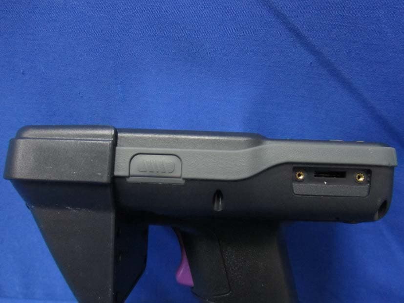
NBF-9X32-0-0
Apr 02, 2013Mobile Computer
Equipment Class
DSS - Part 15 Spread Spectrum Transmitter