NBFAS-8510Handheld Bar Code Scanner
Argox Information Co Ltd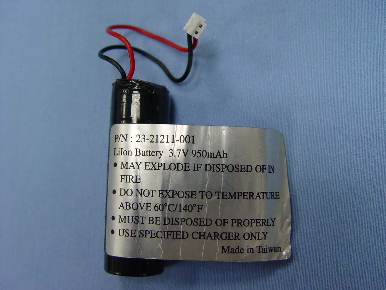
Click to zoom
Application Details
- Equipment Class
- DSS - Part 15 Spread Spectrum Transmitter
- Date of Grant
- Mar 10, 2005
- Application Purpose
- Original Equipment
- Date of Application
- Mar 10, 2005
- Equipment Note
- Handheld Bar Code Scanner
- Frequency Range
- 2402.00000000 - 2480.00000000
- Company
- Argox Information Co Ltd
- Country
- Taiwan
Documents & Files
Document Text
Text extracted from the exhibit documents filed with the FCC. Open a document above to read the original.
Users Manual
User’s Manual Argox Handheld Bar Code Scanner Model No.: 1 USING AS-8510/8512 RADIO CRADLE The AS-8510/8512 radio cradle paired with one AS-8510/8512 scanner, builds a Cordless Reading System for the collection, decoding and transmission of barcoded data. It can be connected to a Host PC through an RS232, Keyboard wedge or USB cable and is suited for a single-cradle layout. The LEDs signal of the AS-8510/8512 radio cradle status, as described in the following: BATTERY: - Green LED blinking: the batter charge is in progress. - Green LED On: the battery is completely charged. TRANSMISSION: - Green LED On: the radio cradle is powered. - Orange LED blinking: the radio cradle receives data and commands from the Host or the scanner. CONNECTING AND DISCONNECTING THE RADIO CARDLE INTERFACE CABLE The radio cradle can be connected to a Host by means of an RS232, Keyboard wedge or USB cable which must be simply plugged into the Host connector, placed on the base of the cradle. In addition the cradle must be connected to an external power supply. To disconnect the cable, insert a paper clip or other small similar object into the hole at the back of the cradle. Push down on the clip while unplugging the cradle. 2 Default setting For each barcode shown as below: Read Enable Code Type 8510 8512 Checksum Verification Enable Checksum Transmission Enable Code ID UPC-A A UPC-E E EAN-13 F EAN-8 FF Code-39 * Interleaved 2 of 5 i Industrial 2 of 5 - - i Matrix 2 of 5 B Codabar % Code-128 # Code-93 & Code-11 One digit O MSI/Plessey @ UK/Plessey @ Telepen S Standard 2 of 5 i China Post t Italian Pharmacode. p Code-16K - - PDF417 - - EAN UCC Composite - - RC 3 Depth-head 35 mm Weight Less than 250g (with a battery) ArgoScan 8510/8512 Specification Model 8510 / 8512 Operational Light Source 635 nm Visible Red LED Optical System 2048 pixel CCD (Charge-coupled device) Depth of Scan Field Up to 600mm (CODE 39, PSC=90%, 20mils) Scanning Width 160mm Scan Speed 400 scans/sec Resolution 0.1mm(4mils) Code39,PCS=90% Print Contrast 25% or more Scanning Angle Front: 60° Rear: 60° Yaw: 70° Decode Capability Autodiscriminates all standard barcodes; Other symbologies can be ordered optionally (2D symbologies for 8512 only) Beeper Operation 7 tones or no beep Indicator Green & Red led Mechanical Length 164 mm Width-handle 30 mm Width-head 78 mm Depth-handle 56 mm 4 Case material ABS (over molded at contact pointed) Cushion material Double injection Cradle interface RS232, Keyboard wedge, USB Electrical Input Voltage (Cradle) 5 VDC ± 10% VDC Power - Operating (Cradle) 5 VDC Power – Standby (Cradle) 5 VDC Current – Operating (Cradle) 132 mA Current – Standby (Cradle) 132 mA Charge Current (Cradle) 340 mA Input Voltage (Scanner) 3.4V ~ 4.2V Power - Operating (Scanner) 3.2V ~ 4.0V Power – Standby (Scanner) 3.4V ~ 4.2V Current – Operating (Scanner) 225 mA Current – Standby (Scanner) 13 mA Light Level Up to 70000 Lux Shock 1.5m drop onto concrete Contaminants Seals to resist airborne particulate contaminants (IP42) 5 Ventilation None required Programming Programming method Manual (Reading special barcode) DOS command through RS-232, Windows configuration program Program upgrade Enabled by built-in flash memory Programmable characteristics Code type selection, check digit selection Decoding option Decoding option Transmitted character delay, Header selection, trailer selection, message suffix, good read beep tone and volume, scanner trigger selection Keyboard emulation type (intermessage delay, keyboard type and keyboard language) Serial interface type (ACK/NAK, Xon/Xoff, RTS/CTS, good read LED control, start/stop bits) 6 Programming the AS-8510 / 8512 To program the 8510 or 8512, you must scan a series of programming barcode in the correct order. Fold out the back cover of this manual. You will see a table of alphanumeric barcodes, which are used to program the various options presented. To program each option, you must: 1. Scan the Program barcode on the parameter setting part. 2. Enter the option mode by scanning the Option Bar Code (also on the Parameter setting part). 3. To the right of the option barcode, the necessary alphanumeric inputs are listed. Scan these alphanumeric entries from the back fold out page. To confirm above steps, you must scan the Finish barcode on the back fold out page. 4. Once you have finished programming. Scan the Exit barcode, listed on the lower right hand corner of each parameter setting part. 7 Option Bar Code Option Alphanumeric Entry Interface selection Keyboard Wedge RS-232 Wand emulation USB Keyboard/RS-232 Auto detection Reserved 00* 01 02 03 04 05 Program Exit Program Barcode Option Barcode Exit Barcode Back Fold Out Finish barcode 8 Exit Interface Selection This decoder built-in scanner comes in one model and supports interfaces such as keyboard wedge, RS232 serial wedge, wand emulation, and the latest USB interface. In most of the cases, simply selecting an appropriate cable with a device code will work for a specific interface. Interface selection: You can change factory interface default for other type interface. By plugging different cables, setting right interface, then the scanner will be changed to another interface. However, you must make sure which cable you need. Keyboard/RS232/UBS Auto detection: By setting this function, it will automatically select the Keyboard wedge or RS-232 or UBS interface for user. Option Bar Code Option Alphanumeric Entry Interface selection Keyboard Wedge RS-232 Wand emulation USB Keyboard /RS232/USB Auto detection Reserved 00 01 02 (8110/8210/8150) 03 04* 05 Program Note:*-Default 9 Exit Keyboard wedge As a keyboard interface, the scanner supports most of the popular PCs and IBM terminals. The installation of the wedge is a fairly simple process without any changes of software or hardware. Keyboard Type: Select keyboard type connector of your host computer. Scanner must be selected to the appropriate host interface cable converter. Option Bar Code Option …
Text truncated - open the document above for the full version.
Cover Letter(s)
1 Helen Zhao Subject:FW: ??: RE: Argox Information Co., Ltd., FCC ID: NBFAS-8510, Assessment NO.: AN05T4618, Notice#1 AS-8510 Scanner Label Smp & Lo... AS-8510 Scanner UserMan revise... From: [email protected] Sent: Friday, March 11, 2005 12:18 AM To: Helen Zhao Cc: Application (CCS TW) (E-mail) Subject: ??: RE: Argox Information Co., Ltd., FCC ID: NBFAS-8510, Assessment NO.: AN05T4618, Notice#1 Dear Helen, Please refer to below for our reply. Best Regards, Ting Question #1: Please explain why FCC DoC logo is necessary placed on the FCC ID label format. The device is a wireless scanner. Ans #1: FCC logo is removed as attached revised label fomat. Question #2: The manual does not contain any information as how to install the software to enable bluetooth function and how to setup communication link between the scanner and the cradle. Please provide basic application information. Ans #2: Please refer to the attached for revised user manual. (See attached file: AS-8510 Scanner Label Smp & Loc revised 0311.pdf)(See attached file: AS-8510 Scanner UserMan revised 0311.pdf) The items indicated above must be submitted before processing can continue on the above referenced application. Failure to provide the requested information within 30 days of the original e-mail date may result in application dismissal and forfeiture of the filing fee. Also, please note that partial responses increase processing time and should not be submitted. Any questions about the content of this correspondence should be directed to the e-mail address listed below the name of the sender.
External Photos
Compliance Certification Services Inc. Report No: 41109408 Date of Issue: February 03, 2005 Page 1 Total Page: 7 Rev. 00 EXTERNAL PHOTOGRAPHS OF EUT Compliance Certification Services Inc. Report No: 41109408 Date of Issue: February 03, 2005 Page 2 Rev. 00 Compliance Certification Services Inc. Report No: 41109408 Date of Issue: February 03, 2005 Page 3 Rev. 00
Internal Photos
Compliance Certification Services Inc. Report No: 41109408 Date of Issue: February 03, 2005 Page 4 Rev. 00 INTERNAL PHOTOGRAPHS OF EUT Compliance Certification Services Inc. Report No: 41109408 Date of Issue: February 03, 2005 Page 5 Rev. 00 Compliance Certification Services Inc. Report No: 41109408 Date of Issue: February 03, 2005 Page 6 Rev. 00 Compliance Certification Services Inc. Report No: 41129001 Date of Issue: December 1, 2004 Page 7 Total Page: 7 Rev. 00
Parts List/Tune Up Info
HIGH FREQUENCY SMD type antennas for BT/802.11b/g application 2.45 GHz size 5.2 × 3.0 DATA SHEET Product specification – Jul 15, 2004 V.3 Phycomp Product specification High Frequency SMD type antennas for BT/802.11b/g application 2.45 GHz size 5.3 × 2.0 2004 Jul 15 Rev.3 2 www.yageo.com QUICK REFERENCE DATA DESCRIPTION VALUE Centre frequency 2.45 GHz 0 type/01type/02 type/03 type/Default/04 type/05 type Bandwidth >100 MHz Gain 4 dBi max. (depends on the special environment) VSWR 2.5 max. (depends on the special environment) Polarization Linear Azimuth beam width Omni-directional Impedance 50 Ω Power dissipation 1 W Operating temperature −55 to +85 °C Terminations NiSn Resistance to soldering heat 260 °C for 10 seconds DESCRIPTION This 2.45 GHz ceramic multilayer antenna has been designed to meet the requirements of the Bluetooth TM(1) and IEEE 802.11b/g wireless communications protocol. It consists of a rectangular block of low-dielectric ceramic material and is fabricated in a water-based non-toxic process. The antenna is capable of providing good connectivity using near 50 Ω microstrip directly onto the PC board. Notes 1. Bluetooth is a trademark owned by Telefonieaktiebolaget L M Ericsson, Sweden. FEATURES • Designed for 2.45 GHz ISM-band • Simplifies antenna circuitry • NiSn lead-free terminations • Suitable for wave and reflow soldering • Supplied in tape on reel. APPLICATIONS • Telecommunications • Computing (PCs, printers, PDAs) • Wireless office data communications including WLAN • Consumer electronics (wireless headphones). Phycomp Product specification High Frequency SMD type antennas for BT/802.11b/g application 2.45 GHz size 5.3 × 2.0 MECHANICAL DATA For dimensions see Table 1. Fig.1. Component outline. L W F W F IWA0001 T C C Physical dimensions Table 1 Antenna dimensions SYMBOL DETAILS DIMENSIONS (mm) L − 5.3 ±0.20 W − 2.0 ±0.20 T − 1.3 ±0.20 F feed termination 2.0 ±0.20 C − 0.4 ±0.25 2004 Jul 15 Rev.3 3 www.yageo.com Phycomp Product specification High Frequency SMD type antennas for BT/802.11b/g application 2.45 GHz size 5.3 × 2.0 2004 Jul 15 Rev.3 4 www.yageo.com For dimensions see Table 2. Fi g.2. Recommend dimensions of solder W L C C Antenna F L 1 IWA0002 FOOTPRINT DIMENSIONS Physical dimensions Table 2 The dimensions of antenna appearance SYMBOL DETAILS DIMENSIONS (mm) L − 5.5 ±0.2 W − 2.2 ±0.2 F feed pad 2.2 ±0.2 C − 0.5 ±0.25 L1 − 4.3 ±0.5 ELECTRICAL CHARACTERISTICS DESCRIPTION VALUE Centre frequency 2.45 GHz 0 type/01type/02 type/03 type/Default/04 type/05 type Bandwidth >100 MHz Gain 4 dBi max. (depends on the special environment) VSWR 2.5 max. (depends on the special environment) Polarization Linear Azimuth beam width Omni-directional Impedance 50 Ω Power dissipation 1 W Operating temperature −55 to +85 °C Terminations NiSn Resistance to soldering heat 260 °C for 10 s Weight 0.05 g/piece Phycomp Product specification High Frequency SMD type antennas for BT/802.11b/g application 2.45 GHz size 5.3 × 2.0 2004 Jul 15 Rev.3 5 www.yageo.com Physical dimensions Table 3 The dimensions of test board SYMBOL DETAILS DIMENSIONS (mm) L1 − 30 L2 − 10.5 W − 18 T − 0.8 T1 − 4.0 T2 − 1.0 T3 − 1.5 T4 − 4.8 T5 − 1.5 T6 − 1.5 50 Ω transmisson line SMA connector Antenna chip Ground areaClear area IWA0003 T 3 T 1 T 2 L 1 L 2 W T 4 T T 6 Magnification of clear area T 5 For dimensions see Table 3. Fig.3. Typical FR4 test board. ANTENNA CHARACTERISTICS IN STANDRD TEST BOARD Phycomp Product specification High Frequency SMD type antennas for BT/802.11b/g application 2.45 GHz size 5.3 × 2.0 2004 Jul 15 Rev.3 6 www.yageo.com Pre-tuning reference only,after-tuning performance is depending on customer installation. Fig.4 The measurements of typical SWR and return loss on standard test board . Marker data: 1: Γ= −10 dB; f= 2.33 GHz 2: Γ= −10 dB; f= 2.60 GHz Marker data: 1: SWR= 2.5; f= 2.30 GHz 2: SWR= 2.5; f= 2.70 GHz 2.02.13.0 f (GHz) SWR 1.0 2.0 3.0 5.0 7.0 6.0 8.0 9.0 10.0 4.0 2.22.32.42.52.62.72.82.9 IWA0004 1 2 2.02.13.0 f (GHz) Γ (dB) 45 40 35 25 15 20 10 5 0 30 2.22.32.42.52.62.72.82.9 IWA0005 1 2 Phycomp Product specification High Frequency SMD type antennas for BT/802.11b/g application 2.45 GHz size 5.3 × 2.0 XY plane YZ plane XZ plane − 270° −180° − 90° 0° 0° 0° −180° − 270° − 90° − 270° − 90° −180° 0° IWA0007 Fig.5 The definitions of X-Y-Z plane and angle for radiation pattern 10 −20 −3040 dBi 1020−3040 1020−3040 XYXZYZ Vertical Horizontal 0° −90°−270° −180° IWA0006 0° −90°−270° −180° −180° 0° −90°−270° 0 − − dBi 0−−− dBi 0−−− Table 4 Max. and avg. antenna gain value of radiation pattern Plane XY (dBi) XZ(dBi) YZ (dBi) Vertical Pol. (max.) −3.8 2.6 −1.8 Vertical Pol. (avg.) −8.4 −1.6 −9.7 Horizontal Pol. (max.) 4.0 −1.9 2.7 Horizontal Pol. (avg.) −2.2 −8.4 −2.1 Total gain (max.) 4.0 2.7 2.7 Total gain (avg.) −1.9 −1.3 −1.9 For antenna gain value see Table 4. Fig.6 Radiation pattern measurements 2004 Jul 15 Rev.3 7 www.yageo.com Phycomp Product specification High Frequency SMD type antennas for BT/802.11b/g application 2.45 GHz size 5.3 × 2.0 ORDERING INFORMATION Components may be ordered by using either a Phycomp’s unique 12NC or the simple 17-digit clear text code (Yageo part number) 12NC ORDERING CODE E XAMPLE: 4311 153 00245 4 3 X X 1 5 3 0 0 2 X X Centre frequency Tolerance Size 5.3 x 2.0 x 1.3 mm 53 Packing 11 13 reel: ∅180 mm; 7", blister, 1000 pcs bulk, 1000 pcs Material 1high-frequency material Family 43antenna IWA0008 2452.45 GHz Default 00 at 100 MHz Impedance Bandwidth 2002.00 GHz 00type 2102.10 GHz 01type 2302.30 GHz 03type 2402.40 GHz 04type 2202.20 GHz 02type 2502.50 GHz 05type Yageo part number E XAMPLE: CAN4311153002451K DESCRIPTION CODE Family CAN43 = antenna products Packing 11 = 180 mm/7” blister Materials 1 = high frequency materials Size 53 = 5.3 × 2.0 × 1.3 mm Tolerance 00 = large than 100 MHz Working Frequency (1) 245 = 2.45 GHz (Default) 200 = 2.0 GHz (00 type) 210 = 2.1 GHz (01 type) 220 = 2.2 GHz (02 type) 230 = 2.3 GHz (03 type) 240 = 2.4 GHz (04 type) 250…
Text truncated - open the document above for the full version.
Test Report
Compliance Certification Services Inc. Report No.: 41109408-RP1 FCC ID: NBFAS-8510 Date of Issue: February 03, 2005 Note: This report shall not be reproduced except in full, without the written approval of Compliance Certification Services Inc. This document may be altered or revised by Compliance Certification Services Inc. personnel only, and shall be noted in the revision section of the document. Page 1 Total Page: 46 Rev. 00 FCC 47 CFR PART 15 SUBPART C TEST REPORT For Handheld Bar Code Scanner Model: AS-8510 Trade Name: Argox Issued to Argox Information Co., Ltd. 7F, NO.126, Lane 235, Pao-Chiao Rd., Hsin Tien, Taipei, Taiwan, R.O.C Issued by Compliance Certification Services Inc. No. 81-1, Lane 210, Bade Rd. 2, Luchu Hsiang, Taoyuan Hsien, (338) Taiwan, R.O.C. TEL: 886-3-324-0332 FAX: 886-3-324-5235 Compliance Certification Services Inc. Report No.: 41109408-RP1 FCC ID: NBFAS-8510 Date of Issue: February 03, 2005 Page 2 Rev. 00 TABLE OF CONTENTS 1. TEST RESULT CERTIFICATION................................................................................................................3 2. EUT DESCRIPTION........................................................................................................................................4 3. TEST METHODOLOGY ................................................................................................................................5 3.1 EUT CONFIGURATION.....................................................................................................................................5 3.2 EUT EXERCISE................................................................................................................................................5 3.3 GENERAL TEST PROCEDURES.........................................................................................................................5 3.4 MODIFICATION..............................................................................................................................................5 3.5 FCC PART 15.205 RESTRICTED BANDS OF OPERATIONS ....................................................................6 3.6 DESCRIPTION OF TEST MODES........................................................................................................................6 4. INSTRUMENT CALIBRATION ....................................................................................................................7 5. FACILITIES AND ACCREDITATIONS ......................................................................................................8 5.1 FACILITIES ...................................................................................................................................................8 5.2 EQUIPMENT ...................................................................................................................................................8 5.3 LABORATORY ACCREDITATIONS AND LISTING...............................................................................................8 5.4 TABLE OF ACCREDITATIONS AND LISTINGS....................................................................................................9 6. SETUP OF EQUIPMENT UNDER TEST ...................................................................................................10 6.1 SETUP CONFIGURATION OF EUT...................................................................................................................10 6.2 SUPPORT EQUIPMENT ..........................................................................................................................10 7. FCC PART 15.247 REQUIREMENTS.........................................................................................................11 7.1 PEAK POWER................................................................................................................................................11 7.2 BAND EDGES MEASUREMENT............................................................................................................12 7.3 PEAK POWER SPECTRAL DENSITY................................................................................................................17 7.4 FREQUENCY SEPARATION ..................................................................................................................20 7.5 NUMBER OF HOPPING FREQUENCY..................................................................................................22 7.6 TIME OF OCCUPANCY (DWELL TIME) ..............................................................................................24 7.7 RADIO FREQUENCY EXPOSURE.....................................................................................................................31 7.8 SPURIOUS EMISSIONS ............................................................................................................................32 7.9 POWERLINE CONDUCTED EMISSIONS...........................................................................................................42 APPENDIX 1 PHOTOGRAPHS OF TEST SETUP ...........................................................................................45 Compliance Certification Services Inc. Report No.: 41109408-RP1 FCC ID: NBFAS-8510 Date of Issue: February 03, 2005 Page 4 Rev. 00 2. EUT DESCRIPTION Product Handheld Bar Code Scanner Trade Name Argox Model Number AS-8510 Model Discrepancy N/A Power Supply LiIon Battery: P/N: 23-21211-001 3.7V, 950mAh Frequency Range 2402 ~ 2480 MHz Transmit Power 4.12 dBm Modulation Technique FHSS Transmit Data Rate 1Mbps Number of Channels 79 Channels Antenna Specification Chip Antenna / Gain: 4.0 dBi Remark: This submittal(s) (test report) is intended for FCC ID: NBFAS-8510 filing to comply with Section 15.207, 15.209 and 15.247 of the FCC Part 15, Subpart C Rules. Compliance Certification Services Inc. Report No.: 41109408-RP1 FCC ID: NBFAS-8510 Date of Issue: February 03, 2005 Page 5 Rev. 00 3. TEST METHODOLO…
Text truncated - open the document above for the full version.
Test Setup Photos
Compliance Certification Services Inc. Report No.: 41109408-RP1 FCC ID: NBFAS-8510 Date of Issue: February 03, 2005 Page 45 Rev. 00 APPENDIX 1 PHOTOGRAPHS OF TEST SETUP Radiated Emission Set up Photos Compliance Certification Services Inc. Report No.: 41109408-RP1 FCC ID: NBFAS-8510 Date of Issue: February 03, 2005 Page 46 Rev. 00 Conducted Emission Set Up Photos
Contact Information
Applicant
Bob Wang(Manager)
Test Firm
Compliance Certification Services Inc.Kurt Chen
Technical Specifications
| # | Rule Parts | Frequency Range | Power Output |
|---|---|---|---|
| 1 | 15C | 2.40 GHz - 2.48 GHz | 2.58 mW |
Other Applications from Argox Information Co Ltd

NBF-AS-9400BT
Nov 22, 2022Barcode Scanner
Equipment Class
DTS - Digital Transmission System
NBF-AI-68X1
Sep 20, 2015Handheld Barcode Scanner
Equipment Class
DSS - Part 15 Spread Spectrum Transmitter
NBF-PA-2X10
Feb 25, 2014Mobile Computer
Equipment Class
DSS - Part 15 Spread Spectrum Transmitter
NBF-9X30-1-1
Apr 23, 2013Mobile Computer
Equipment Class
DSS - Part 15 Spread Spectrum Transmitter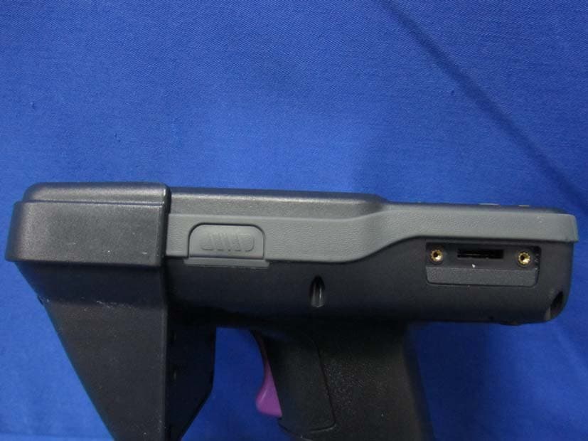
NBF-9X32-0-0
Apr 02, 2013Mobile Computer
Equipment Class
DSS - Part 15 Spread Spectrum Transmitter