NBFAS-8520-BCradle
Argox Information Co Ltd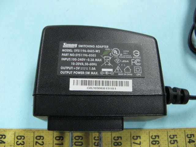
Click to zoom
Application Details
- Equipment Class
- DSS - Part 15 Spread Spectrum Transmitter
- Date of Grant
- Mar 24, 2009
- Application Purpose
- Original Equipment
- Date of Application
- Mar 24, 2009
- Equipment Note
- Cradle
- Frequency Range
- 2402.00000000 - 2480.00000000
- Company
- Argox Information Co Ltd
- Country
- Taiwan
Documents & Files
Document Text
Text extracted from the exhibit documents filed with the FCC. Open a document above to read the original.
Users Manual
1 Installation The AS-8520 Wireless Imager is easy to install and use. Please see the following figure showing the steps to perform the installation. * Note: Turn off the host computer before installation. 1. Connect the interface (I/F) cable to the cradle. 2. Connect the power cord to the cradle. 3. Route the I/F cable and power cord through the notch. 4. Connect the I/F cable to the host computer communication port. 5. Connect the AC adapter to the wall outlet. 6. Place the imager in the cradle and verify the charge LED is flashing. Charge the battery for at least 8 hours before the first use. 7. To verify operation, please link the imager with cradle first (Refer to “Wireless Connection” in page 5). Point the imager at the barcode and pull the trigger. The imager should emit a beep indicating that the barcode has been scanned and transmitted to the cradle successfully. 2 How To Scan 1. The imager must be pointed at slight angle to the barcode so that the light reflected off the barcode can be seen by the imager. Do not hold the imager perpendicular to the barcode. 2. The scan line must cross the entire barcode. The imager can not read the barcode data without seeing the entire barcode. 3 Troubleshooting If the imager can not operate properly, the following checks should be performed: 1. The cradle uses an external power supply and the external power supply has failed, the imager will not operate. Change the power supply with a known good power supply and reset the imager. 2. Verify the interface cable is securely connected to the host computer. Consult your technical support personnel or refer to your host system manual to verify the proper connection for the imager. 4 3. Verify the interface cable is securely connected to the cradle. 4. Check that the barcodes are of sufficient quality to be recognized by the imager. Wrinkled, smudged, or torn labels will cause the imager to not read at all. Scan a known good label to check the imager’s read operation. 5. Ensure that the cradle’s interface type is compatible with the host computer by consulting your host system manual. 5 Wireless Connection Linking the imager with the cradle Follow these instructions to link the two devices: 1. Connect power to the cradle. The radio LED (marked with a light symbol) will blink amber and the cradle will beep. 2. To ensure the cradle is unlinked from any other imager, check if the cradle send inquiry beep or not (see Inquiry Beep Control in page 17). 3. Read the link label on the bottom of the cradle with the imager. The imager will sound a good read beep and the LED will flash amber. 4. Re-place the imager in the cradle to continue the charge. Once an imager is linked to a cradle, they will remain linked until specific action is taken to unlink them (see Unlinking). They will remain linked if the cradle is unplugged, if the battery is removed from the imager or if the entire charge is used up, and if the imager is taken out of range of the cradle. Under normal operation, scanning of the link label will only be required once in the life of the product. 6 Unlinking There are three ways to unlink an imager from a cradle: Force imager to disconnect and sleep 1. Scan the “Force imager to disconnect and sleep” barcode – Reading the unlink barcode above while the imager is in range of the cradle will break the link between the two devices and allow another imager to link to the cradle. It will also have the imager in Deep Sleep Mode. If the barcode is read when the imager is out of range of its linked cradle, the imager will unlink, but the cradle will remain linked to the imager and will not allow another imager to be linked to it. In this case, you may perform the item 2 below to link another imager. 2. Scan the Link Label and put on the original cradle – If the cradle is linked with an imager and the original pair was stopped by out of range of the cradle or out of battery of the imager, scan the link label of the cradle with a new imager and then put on the cradle, the cradle will drop the original pair and establish a new link with the new imager. 3. Scan the Link Label on an alternate cradle – Scanning the link label on a cradle will drop the link between the original pair and establish a link between the imager and new cradle. If the new link is performed within range of the old cradle, it is free to establish a link to the next imager that reads its link label. If it is done outside of the range of the old cradle, it retains its old link and will not allow a new imager to link to it until a new imager scan the link label and put on the cradle. *$%-$ZZ%%* 7 Battery Charging The imager contains a 1000mAh Lithium-Ion rechargeable battery. A full charged battery will provide up to 15,000 scans over a 12 hours period. Actual charge life on the imager will depend on the configuration of how the imager is configured via the programmable feature in this manual; in particular, Deep Sleep Mode settings can impact battery life. When the imager is placed in the cradle, the battery will automatically charge. While charging is taking place, the charging LED (marked with a battery symbol) will blink green. When the battery is fully charged, the charging LED will stay on a solid green. If there is an error in charging either with a failure in the charging circuit or with a failure of the battery, the charging LED will flash red. When this happens, the battery needs to be replaced. 8 How to Change the Battery In case the contained battery inside the imager needs to be replaced, please follow the procedures below: 1. Loosen the screw at the bottom of the imager. 2. Take off the battery container out of the imager. 5. Use a new battery pack and replace the used one. 3. Disconnect the battery cable connector from the handle board. 4. Remove the used battery from the battery container. 9 Note: DO NOT touch the PCBA inside the imager when replacing the battery. Improper operation may damage the imager. 6. Place the new bat…
Text truncated - open the document above for the full version.
External Photos
ETC Report No. : 08-12-RBF-134-05 FCC ID.: NBFAS-8520-B Rev. No 2.1 CONSTRUCTION PHOTOS OF EUT Top View of EUT Bottom View of EUT ETC Report No. : 08-12-RBF-134-05 FCC ID.: NBFAS-8520-B Rev. No 2.1 CONSTRUCTION PHOTOS OF EUT Side View of EUT Rear View of EUT ETC Report No. : 08-12-RBF-134-05 FCC ID.: NBFAS-8520-B Rev. No 2.1 CONSTRUCTION PHOTOS OF EUT Side View of EUT Front View of EUT ETC Report No. : 08-12-RBF-134-05 FCC ID.: NBFAS-8520-B Rev. No 2.1 CONSTRUCTION PHOTOS OF EUT Top View of Adaptor Bottom View of Adaptor ETC Report No. : 08-12-RBF-134-05 FCC ID.: NBFAS-8520-B Rev. No 2.1 CONSTRUCTION PHOTOS OF EUT PS2 Cable PS2 Cable ETC Report No. : 08-12-RBF-134-05 FCC ID.: NBFAS-8520-B Rev. No 2.1 CONSTRUCTION PHOTOS OF EUT USB Cable
ID Label/Location Info
40mm 26mm
Test Setup Photos
ETC Report No. : 08-12-RBF-134-05 FCC ID.: NBFAS-8520-B Rev. No 2.1 Photos of Radiation Measuring Setup ETC Report No. : 08-12-RBF-134-05 FCC ID.: NBFAS-8520-B Rev. No 2.1 ETC Report No. : 08-12-RBF-134-05 FCC ID.: NBFAS-8520-B Rev. No 2.1 Photos of Conduction Measuring Setup ETC Report No. : 08-12-RBF-134-05 FCC ID.: NBFAS-8520-B Rev. No 2.1
Contact Information
Applicant
Bob Wang(Manager)
Test Firm
Electronics Testing Center, TaiwanWill Yauo
Technical Specifications
| # | Rule Parts | Frequency Range | Power Output |
|---|---|---|---|
| 1 | 15C | 2.40 GHz - 2.48 GHz | 21.88 mW |
Other Applications from Argox Information Co Ltd

NBF-AS-9400BT
Nov 22, 2022Barcode Scanner
Equipment Class
DTS - Digital Transmission System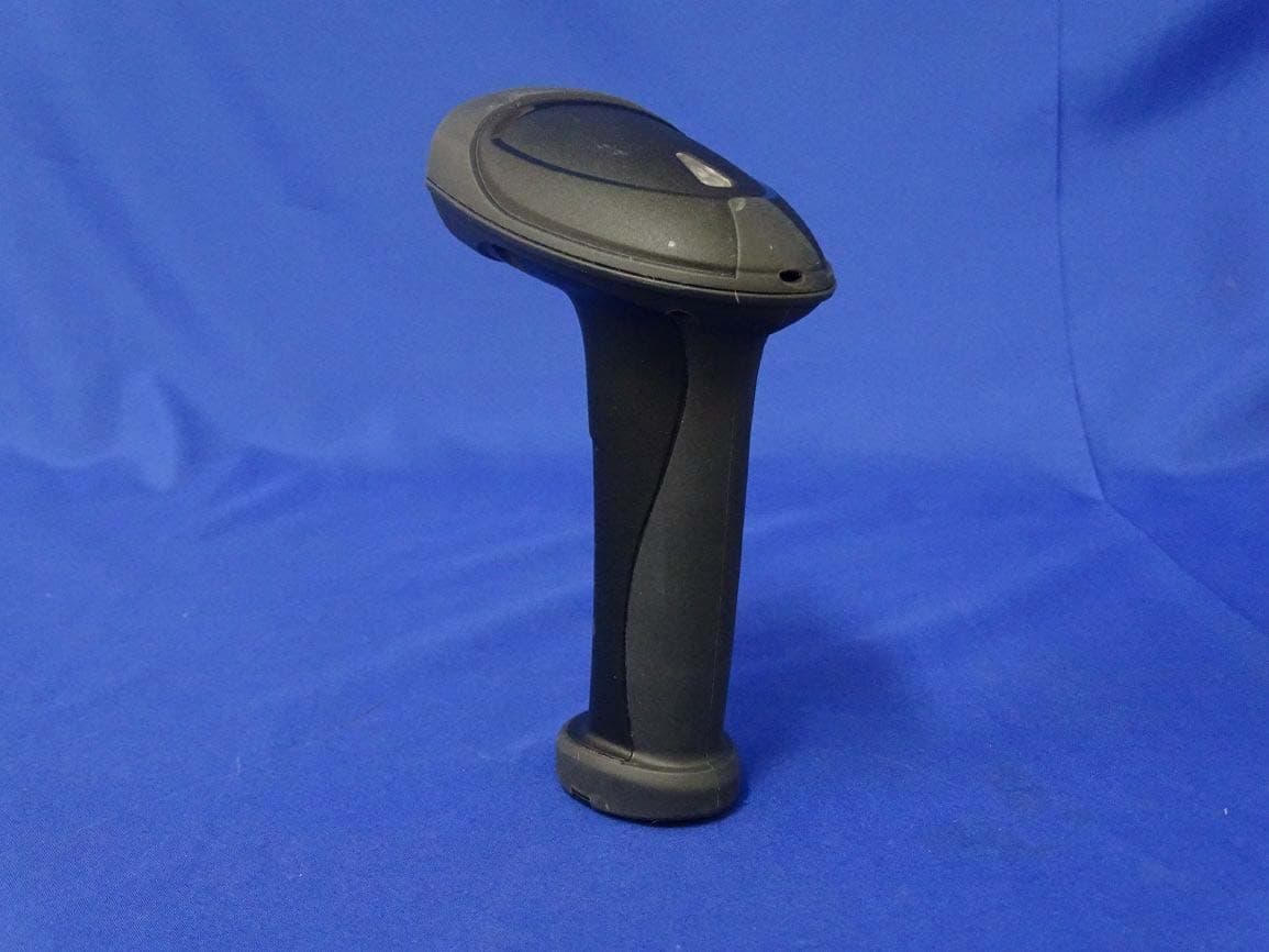
NBF-AI-68X1
Sep 20, 2015Handheld Barcode Scanner
Equipment Class
DSS - Part 15 Spread Spectrum Transmitter
NBF-PA-2X10
Feb 25, 2014Mobile Computer
Equipment Class
DSS - Part 15 Spread Spectrum Transmitter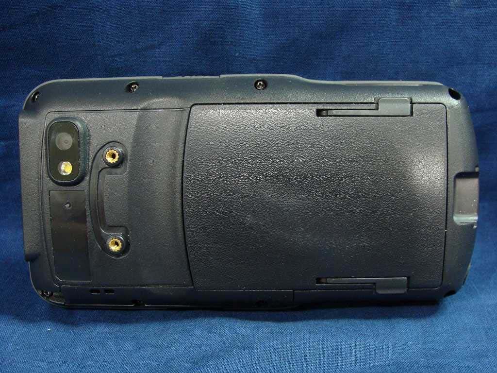
NBF-9X30-1-1
Apr 23, 2013Mobile Computer
Equipment Class
DSS - Part 15 Spread Spectrum Transmitter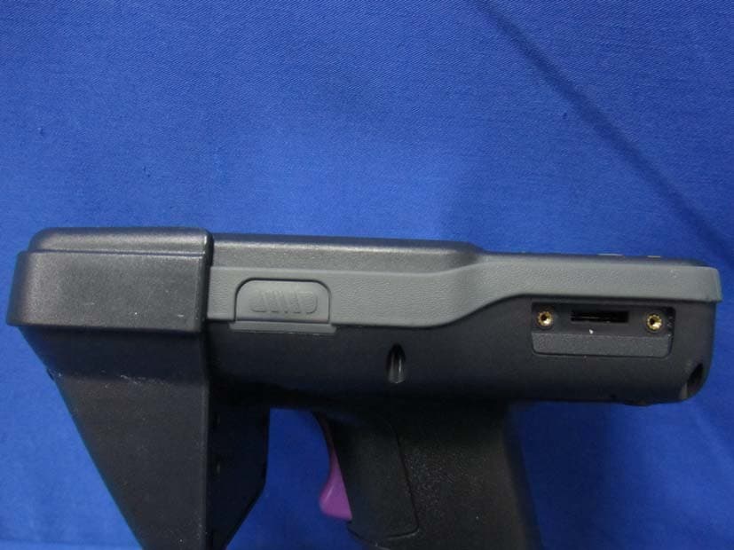
NBF-9X32-0-0
Apr 02, 2013Mobile Computer
Equipment Class
DSS - Part 15 Spread Spectrum Transmitter