NCG-5Electronic Ballast
Cooper Lighting
Click to zoom
Application Details
- Equipment Class
- 8CC - Part 18 Consumer Device
- Date of Grant
- Dec 09, 1999
- Application Purpose
- Original Equipment
- Date of Application
- Sep 21, 1999
- Equipment Note
- Electronic Ballast
- Frequency Range
- 0.04200000 - 0.04200000
- Company
- Cooper Lighting
- Country
- United States
Documents & Files
Document Text
Text extracted from the exhibit documents filed with the FCC. Open a document above to read the original.
Cover Letter(s)
Page 1 of 1 FCC ID: NCG-5 Letter of Authorization
Cover Letter(s)
Page 1 of 1 FCC ID: NCG-5 Letter of Confidentiality
External Photos
Page 1 of 2 FCC ID: NCG-5 External Photographs of EUT External Front Page 2 of 2 FCC ID: XXXXX External Photographs of EUT External Back
Internal Photos
Page 1 of 1 FCC ID: NCG-5 Internal Photographs of EUT PCB Component side PCB Foil side
Operational Description
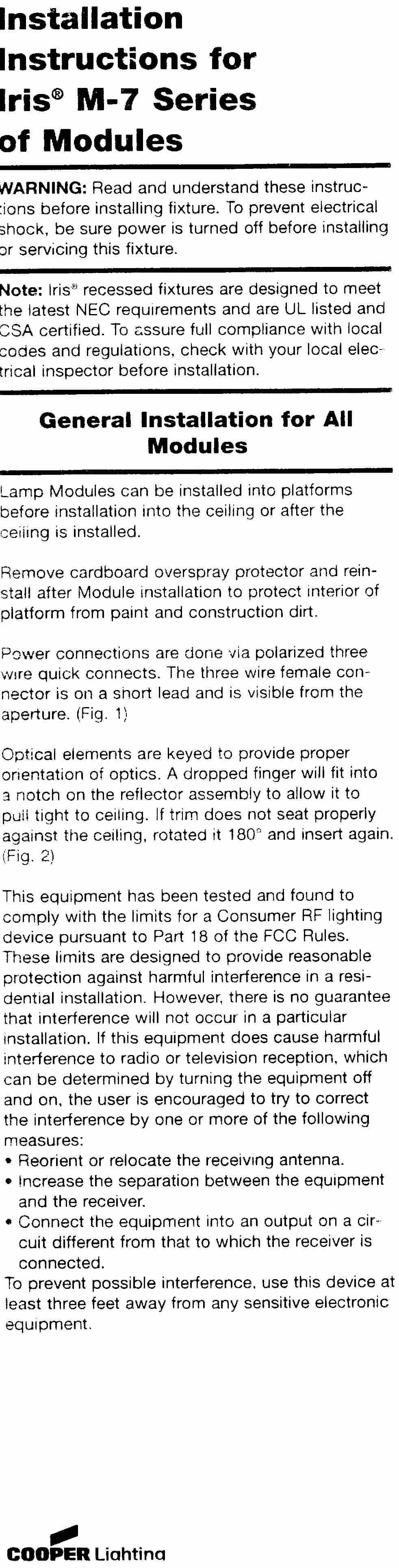
Page 1 of 1 FCC ID: NCG-5 Product Description The Iris M32T Module incorporates a high power factor electronic ballast which operates a 32 watt 4 pin triple tube compact fluorescent lamp and is used in either a M-5 or M-7 housing. Both the M-5 and M-7 housings are intended for residential application and are UL listed for direct contact with insulation. Operating Description
Test Report
Radiometrics Midwest Corporation Test Document RP-3979 Issue Date: 10/19/99 This report concerns: Original grant Equipment type: Consumer RF Lighting device Tests Performed ForTest Facility Cooper Lighting 1121 Highway 74 South Peachtree City, GA 30269 Radiometrics Midwest Corporation 12 East Devonwood Romeoville, IL 60446 Phone: (815) 293-0772 FAX: (815) 293-0820 [email protected] Test Report Written ByTest Report Approved By Joseph Strzelecki Senior EMC Engineer NARTE EMC-000877-NE Chris W. Carlson Director of Engineering NARTE EMC-000921-NE MEASUREMENT/TECHNICAL REPORT Cooper Lighting Models: M-5 & M-7 FCC ID: NCG-5 RF Emission Measurements Performed For Determination of Compliance with the US Code of Federal Regulations Title 47, Chapter I, FCC Part 18 As Required for Certification for ISM Equipment FCC ID: NCG-5 Page 2RP-3979 Table of Contents 1.0 General Information ............................................................................................................. 3 1.1 Product Description ............................................................................................................. 3 1.2 Related Submittals............................................................................................................... 3 1.3 Tested System Details......................................................................................................... 3 1.4 Test Methodology ................................................................................................................ 3 1.5 Test Facility.......................................................................................................................... 3 2.0 System Test Configuration ..................................................................................................4 2.1 Justification .......................................................................................................................... 4 2.2 Special Accessories............................................................................................................. 4 2.3 Equipment Modifications...................................................................................................... 4 2.4 Configuration of Tested Systems......................................................................................... 4 Figure 2.1 Configuration of Tested System ............................................................................... 4 3.0 Conducted Emission Data ................................................................................................... 5 FCC ID: NCG-5 Page 3RP-3979 1.0 General Information 1.1 Product Description The EUT (Equipment Under Test) is a commercial lighting fixture and power supply in one (L = 4.125” X W = 2.875” X H = 1.25”) package. The EUT is part of lighting fixtures from Cooper Lighting. The Iris M32T module was used in both the M-5 and M-7 housings. The products use the same RF circuitry and the same ballast. The M-5 has a 32 Watt light and the M-7 has a 42 watt light. Both items were fully tested because of the two power levels. These products are directed toward the residential market. The input power requirements are 120 VAC at 60 Hz. 1.2 Related Submittals Cooper Lighting is not submitting any other submittals related to the EUT. 1.3 Tested System Details The FCC IDs for all equipment, plus descriptions of all cables used in the tested system are: Model Number Serial NumberFCC ID Manufacturer & Description Cable Descriptions M/N: Iris M-5 (EUT)NCG-5Cooper Lighting Lighting Fixture & Housing Unshielded, 1 meter Power Cord M/N: Iris M-7 (EUT)NCG-5Cooper Lighting Lighting Fixture & Housing Unshielded, 1 meter Power Cord 1.4 Test Methodology Testing was performed according to the procedures in FCC/OET MP-5 and FCC rules part 18. The tests were performed from 450 kHz to 30 MHz. The EUT’s power supply had a frequency output value of 42 kHz modulated with 60 Hz. Since this is the highest frequency used in the EUT, only conducted emissions testing was done as per section 18.309. Conducted emission measurements were performed using an Electrometrics Model FCC/VDE 50/2 Line Impedance Stabilization Network (LISN) as the pick-up device. 1.5 Test Facility The conducted measurement facility is located on 12 East Devonwood, Illinois. This site has been fully described in a report (31040/SIT) submitted to your office. FCC ID: NCG-5 Page 4RP-3979 2.0 System Test Configuration The system was configured for testing in a typical fashion (as a customer would normally use it). Power was supplied at 115 VAC with a three wire, one meter, unshielded cord. 2.1 Justification Since 42 kHz was the highest frequency used in the EUT, only conducted emissions testing was done as per section 18.309. 2.2 Special Accessories There were no special accessories used to achieve compliance. 2.3 Equipment Modifications No equipment modifications were made to the EUT to achieve compliance. 2.4 Configuration of Tested Systems Figure 2.1 Configuration of Tested System AC Mains To Spec An 1) Housing Unit 2) EUT Notes: • LISN at least 80 cm from EUT chassis • Vertical conductive plane 40 cm from rear of table top • Table is 80 cm high •EUT power cord not bundled LISN 1 2 FCC ID: NCG-5 Page 5RP-3979 3.0 Conducted Emission Data 3.1 The initial step in collecting conducted data is a spectrum analyzer peak scan and plotting the measurement range. Significant peaks are marked, then measured using a quasi-peak detector. The following represents the worst case emissions after maximizing. IRIS M5 AnalyzerCableStrength LineFreq.ReadingLossof SignalLimitMargin TestedMHzdBuVdBdBuVdBuVdB AC Hot0.460741.40.141.548.06.5 AC Hot3.85439.40.139.548.08.5 AC Hot12.5439.70.239.848.08.2 Neutral0.47427.70.127.848.020.2 Neutral0.53527.50.127.648.020.4 Neutral13.8327.80.227.948.020.1 IRIS M-7 AnalyzerCableStrength LineFreq.ReadingLossof SignalLimitMargin TestedMHzdBuVdBdBuVdBuVdB AC Hot0.45227.30.127.448.020.6 AC Ho…
Text truncated - open the document above for the full version.
Test Setup Photos
Page 1 of 1 FCC ID: NCG-5 Test setup Photographs Conducted Emissions Conducted Emissions
Contact Information
Applicant
Scott Formel(Director of Engineering)
Technical Contact
Radiometrics Midwest CorporationJoseph R Strzelecki
[email protected]815-293-0772
12 East Devonwood Av. · Romeoville, Illinois · United States
Non-Technical Contact
Radiometrics Midwest CorporationJoan E Strzelecki
[email protected]815-293-0772
Test Firm
Radiometrics Midwest CorporationJoseph Strzelecki
815-293-0772Fax: 815-293-0820
Technical Specifications
| # | Rule Parts | Frequency Range | Power Output |
|---|---|---|---|
| 1 | 18 | 0.042 MHz - 0.042 MHz | - |
Other Applications from Cooper Lighting

NCG-MS180D
Aug 14, 2011Motion Detector
Equipment Class
FDS - Part 15 Field Disturbance Sensor
NCG-MC1
Dec 13, 20062.4GHz PIR Activated Lighting Camera System
Equipment Class
DXX - Part 15 Low Power Communication Device Transmitter
NCG-TS180DC
Apr 10, 2005PIR Transmitter
Equipment Class
DSC - Part 15 Security/Remote Control Transmitter
NCG-T180AC
Jul 28, 2003Lighting Controller
Equipment Class
DSC - Part 15 Security/Remote Control Transmitter
NCG-T180DC
Jul 15, 2003Lighting Controller
Equipment Class
DSC - Part 15 Security/Remote Control Transmitter