NCT048L12Industrial Remote Controller
Gain Electronic Co Ltd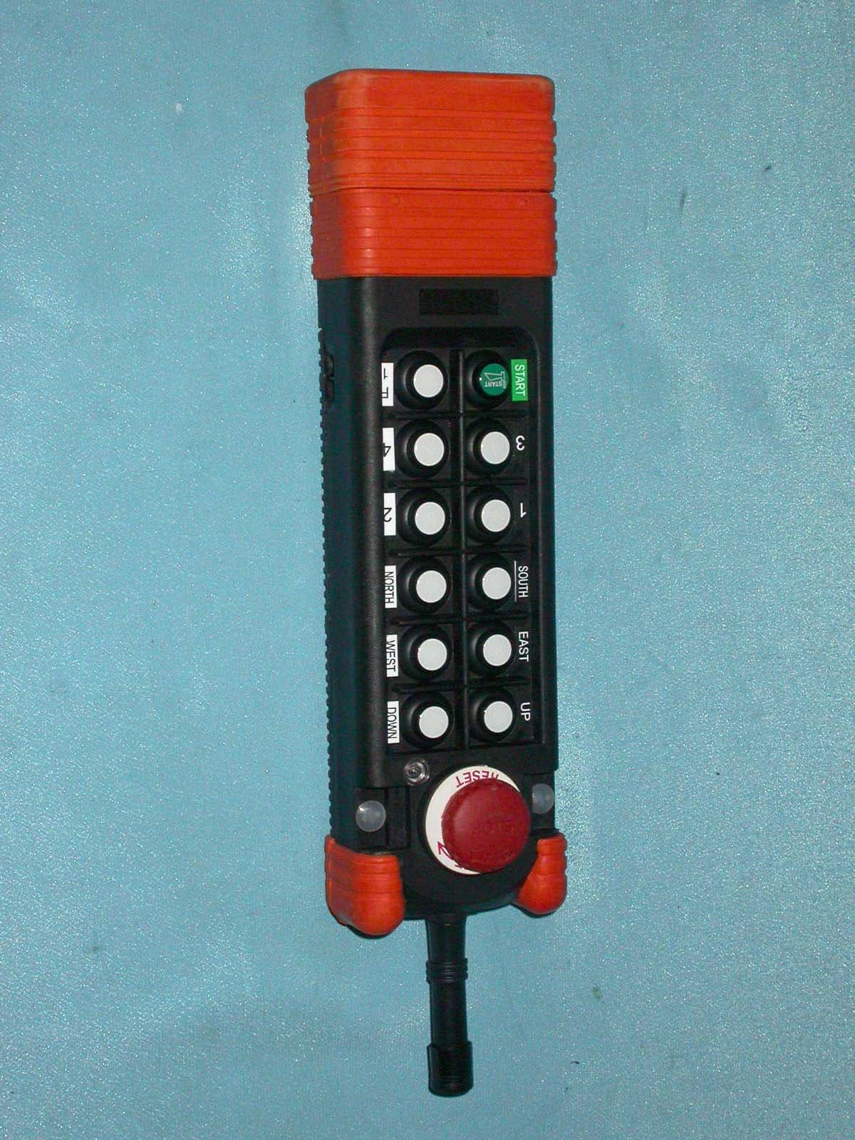
Click to zoom
Application Details
- Equipment Class
- DSC - Part 15 Security/Remote Control Transmitter
- Date of Grant
- Sep 29, 2004
- Application Purpose
- Original Equipment
- Date of Application
- Sep 29, 2004
- Equipment Note
- Industrial Remote Controller
- Frequency Range
- 310.00000000 - 320.00000000
- Company
- Gain Electronic Co Ltd
- Country
- Taiwan
Documents & Files
Document Text
Text extracted from the exhibit documents filed with the FCC. Open a document above to read the original.
Users Manual
SAGA1-L12 Industrial Remote Controller Operating Manual Gain Electronic Co., Ltd. ® 1 FCC Caution: "Changes or modifications not expressly approved by the party responsible for compliance could void the user's authority to operate the equipment." Warranty Gain Electronic Co., Ltd. guarantees that this product meets its published specifications at the time of shipment from the factory. Under proper installation it should work as expected. Warranty Period This equipment is warranted against defects in material and manufacturing for a period of one year from the date of shipment. During the warranty period, GAIN is responsible for necessary repairs as long as the product can be proved to be defective. For warranty service or repair this product must be returned to a service facility designated by GAIN. Buyer will pay shipping charges to GAIN while GAIN will pay return shipping charges. Excluded Items This warranty does not include consumptive parts such as batteries, fuses, buttons, relays. Also this warranty does not cover defects caused by improper installation, improper or insufficient maintenance, unauthorized modification, improper operation, ignorance of environmental specifications, or improper software or interfacing. Remarks No other warranty is expressed or implied, except for the above mentioned.◎ The remedies provided herein are the buyer’s sole and e◎xclusive remedies. GAIN shall not be liable for any direct, indirect, special, incidental or consequential damages. Attention ◎ Never dismantle the equipment by any unauthorized personnel, or equipment may be damaged. ◎ After finishing operation of SAGA1-L12 radio controller shut off main power to the crane, power to receiver, and remove transmitter key. If transmitter’s power is controlled by “rotary key switch”, then need turn the key to “OFF” position and remove it. ◎ The crane should be equipped with main power relay, limit switch and other safety devices. Precautions ( I ) To avoid any interference, the receiver must be placed as far as possible from frequency inverter and power cable as possible. Precaution ( II ) The receiver should be installed on the top of the electrical control box. Do not mount the receiver inside the electrical control box. Emergency In case of Emergency, please follow the procedure below and contact the distributor for service immediately. 1. Press EMS button of transmitter. 2. Remove the key from transmitter. 3. Switch off the main power of crane. 4. Contact distributor nearest you immediately. 2 SAGA1-L12 Standard Accessories When you get a standard and full set of SAGA1-L12 system, it includes the following item.: Remarks: (1). Hamming Distance------------- ≧ 4 (2). I.D. Code--------------------------More than 42 billion ID Code(32bit) (3). Channel Spacing----------------267.5KHz (1)Transmitter, one unit.(2)Receiver, one unit. SAGA1-L12 Operation 3 SAGA1-L12 Transmitter’s parts Remarks: (1). Power----------------------Two 1.5Volt Alkaline Batteries ( AA Size ) (2). Dimensions----------------274 × 77 × 42mm (3). Weight---------------------about 540g ( W/batteries ) EMS Mushroom Motion Pushbutton Start Pushbutton Antenna LED Indicator 4 SAGA1-L12 Receiver’s parts Remarks : (1). Input Voltage------------------------------110VAC ( 50/60Hz )± 10% (2). Output Relays-----------------------------10A/250VAC. (3). Dimensions---------------------------------253 × 267 × 150mm ( L × W × H ) (4). Weight--------------------------------------about 3000g ( W/O wire cable ) Circuit Diagram Cable 5 How to use 1. Insert 2 AA-size alkaline batteries into battery compartment. 2. Insert magnetic key or rotary key and switch to ON position. 3. Follow the Power-On procedure to energize the main relay inside receiver. 4. Operate normally according to the function settings have been done. 5. After operation, please proceed as following: (1) Press EMS pushbutton /mushroom, (2) remove the key and keep it in safe place, (3) Switch off the equipment’s main power (e.g. Crane) How to change quartz from transmitter/ receiver & identify frequency quartz It’s simple to change frequency of the new SAGA1-L12 series. The system’s frequency can be changed simply by replacing correspondent frequency quartz in both the TX and RX. Note: For replacing the new quartz, there are 2 types of frequency are available (VHF & UHF). Do not replace the VHF crystal unit into UHF PC Board. The indication of frequency type (VHF or UHF) is shown on the PC Board with a check mark “v” Instructions: (1). Pry up the crystal unit with a flat screwdriver (2). Remove the crystal unit from the system. (3). Use a needle nose pliers to straighten both pins of the new crystal unit. (4). Insert the new crystal unit vertically into the PC board. (5). Press the new crystal down into the socket. Note: the frequency will be different when plugging the same crystal into the TX or RX, for example, ID Code Remote Setting ID Code Remote setting allows you to overwrite the receiver ID code if Receiver or Transmitter is damaged. Before remote setting, one must make sure both TX and RX are in same frequency channel. By using remote setting, receiver ID code will be overwriting by the transmitter. Prior to remote setting, please follow the instruction below, (a) Make sure both TX and RX are same model and in the same frequency channel. (b) To avoid interference during remote setting, place the transmitter to RX as close as possible. (c) Turn off RX power completely (MAIN SWITCH) for 20 seconds and turn it on again. (d) Complete the remote setting within 4 minutes after turning on the RX. The RX will NOT accept the remote setting signal after 4 minutes. Instructions: (1) Depress the TX Emergency Stop (For those systems without a Mushroom style stop button that stays depressed, please hold down the “STOP” pushbutton) (2) Press UP pushbutton and hold it. 1 2 3 4 5 T : 321.00 MHz R : 331.70 MHz Frequency for TX is 321.00 MHz Frequency for RX is 331.70 MHz 6 (3) Press DOWN pushbutton…
Text truncated - open the document above for the full version.
External Photos
Company: GAIN ELECTRONIC CO., LTD Page : 1 of 5 Product : Industrial Remote Controller Model : SAGA1-L12; SAGA1-L12-1 Company: GAIN ELECTRONIC CO., LTD Page : 2 of 5 Product : Industrial Remote Controller Model : SAGA1-L12; SAGA1-L12-1 Company: GAIN ELECTRONIC CO., LTD Page : 3 of 5 Product : Industrial Remote Controller Model : SAGA1-L12; SAGA1-L12-1 Company: GAIN ELECTRONIC CO., LTD Page : 4 of 5 Product : Industrial Remote Controller Model : SAGA1-L12; SAGA1-L12-1 Company: GAIN ELECTRONIC CO., LTD Page : 5 of 5 Product : Industrial Remote Controller Model : SAGA1-L12; SAGA1-L12-1
ID Label/Location Info
Company: GAIN ELECTRONIC CO., LTD Model: SAGA1-L12 Product : Industrial Remote Controller GAIN ELECTRONIC CO., LTD Model No: SAGA1-L12 FCC ID:NCT048L12 This device complies with part 15 of the FCC Rules. Operation is subject to the following two conditions: [1] this device may not cause harmful interference and [2] this device must accept any interference received, including interference that may cause undesired operation. S/N: Made in Taiwan
Internal Photos
Company: GAIN ELECTRONIC CO., LTD Page : 1 of 15 Product : Industrial Remote Controller Model : SAGA1-L12; SAGA1-L12-1 Company: GAIN ELECTRONIC CO., LTD Page : 2 of 15 Product : Industrial Remote Controller Model : SAGA1-L12; SAGA1-L12-1 Company: GAIN ELECTRONIC CO., LTD Page : 3 of 15 Product : Industrial Remote Controller Model : SAGA1-L12; SAGA1-L12-1 Company: GAIN ELECTRONIC CO., LTD Page : 4 of 15 Product : Industrial Remote Controller Model : SAGA1-L12; SAGA1-L12-1 Company: GAIN ELECTRONIC CO., LTD Page : 5 of 15 Product : Industrial Remote Controller Model : SAGA1-L12; SAGA1-L12-1 Company: GAIN ELECTRONIC CO., LTD Page : 6 of 15 Product : Industrial Remote Controller Model : SAGA1-L12; SAGA1-L12-1 Company: GAIN ELECTRONIC CO., LTD Page : 7 of 15 Product : Industrial Remote Controller Model : SAGA1-L12; SAGA1-L12-1 Company: GAIN ELECTRONIC CO., LTD Page : 8 of 15 Product : Industrial Remote Controller Model : SAGA1-L12; SAGA1-L12-1 Company: GAIN ELECTRONIC CO., LTD Page : 9 of 15 Product : Industrial Remote Controller Model : SAGA1-L12; SAGA1-L12-1 Company: GAIN ELECTRONIC CO., LTD Page : 10 of 15 Product : Industrial Remote Controller Model : SAGA1-L12; SAGA1-L12-1 Company: GAIN ELECTRONIC CO., LTD Page : 11 of 15 Product : Industrial Remote Controller Model : SAGA1-L12; SAGA1-L12-1 Company: GAIN ELECTRONIC CO., LTD Page : 12 of 15 Product : Industrial Remote Controller Model : SAGA1-L12; SAGA1-L12-1 Company: GAIN ELECTRONIC CO., LTD Page : 13 of 15 Product : Industrial Remote Controller Model : SAGA1-L12; SAGA1-L12-1 Company: GAIN ELECTRONIC CO., LTD Page : 14 of 15 Product : Industrial Remote Controller Model : SAGA1-L12; SAGA1-L12-1 Company: GAIN ELECTRONIC CO., LTD Page : 15 of 15 Product : Industrial Remote Controller Model : SAGA1-L12; SAGA1-L12-1
Operational Description
Description of operational Principle of Transmitter Unit When the pushbutton on the Transmitter is pressed, the MCU (Micro Control Unit) immediately sends the signal of the PWR CTRL (Power Control) and FSK DATA (Frequency Shift Key DATA) to make the TX IC (Transmitter IC) worked. As soon as the TX IC starts working, the XTAL (Crystal) and the VCO (Voltage Control Oscillator) get oscillating, then the VCO goes through 1/64 Frequency Divider to the PD (Phase Detector), and continue to LF (Low pass Filter) then back to the VCO to make the frequency locked that gets through 1/2 Frequency Divider and AMP (Amplifier) and LPF (Low Pass Filter), at last transmitting the signal out by the Antenna of the Transmitter.
Test Report
Ecom Sertech Corp. Rm. 258, Bldg. 17, NO.195, Sec. 4 Chung Hsing Rd.,Chu -Tung Chen, Hsinchu, Taiwan 310, R.O.C TEL:886 - 3 - 5918012 FAX : 886 - 3 - 5825720 FCC ID :NCT048L12 Report No.:ER04-08-031FRF Page 1 of 32 TEST REPORT Product Name : Industrial Remote Controller Model Number : SAGA1-L12 Data Applies to : SAGA1-L12-1 Brand Name : SAGA FCC ID : NCT048L12 Applicant : GAIN ELECTRONIC CO., LTD Address : 4F-1, NO. 288-5, Hsin-Ya Rd, Chien-Chen Zone(806), Kaohsiung, Taiwan, R.O.C. Received Date : August 13, 2004 Tested Date : August 13 ~ October 06, 2004 Notes : 1. This report will be invalid if duplicated or photocopied in part. 2. This report refers only to the specimen(s) submitted to testing, and be invalid as separately used. 3. This report is invalid without examination stamp and signature of this institute. 4. The tested specimen(s) will be preserved for thirty days from the data issued. 5. The report must not be used to claim product certification, approval, or endorsement by NVLAP, NIST, or any agency of the federal government. Ecom Sertech Corp. Rm. 258, Bldg. 17, NO.195, Sec. 4 Chung Hsing Rd.,Chu -Tung Chen, Hsinchu, Taiwan 310, R.O.C TEL:886 - 3 - 5918012 FAX : 886 - 3 - 5825720 FCC ID :NCT048L12 Report No.:ER04-08-031FRF Page 2 of 32 Test Report Certification Product Name : Industrial Remote Controller Model Number : SAGA1-L12 Data Applies to : SAGA1-L12-1 Brand Name : SAGA FCC ID : NCT048L12 Applicant : GAIN ELECTRONIC CO., LTD Measurement Standard : 47 CFR Part 15 Subpart B and C(Section 15.231) ANSI C63.4-2001 WE HEREBY CERTIFY THAT: The measurements shown in the attachment were made in accordance with the procedures indicated, and the energy emitted by the equipment was found to be within the limits applicable. We assume full responsibility for the accuracy and completeness of these measurements and vouch for the qualifications of all persons taking them. Ecom Sertech Corp. Rm. 258, Bldg. 17, NO.195, Sec. 4 Chung Hsing Rd.,Chu -Tung Chen, Hsinchu, Taiwan 310, R.O.C TEL:886 - 3 - 5918012 FAX : 886 - 3 - 5825720 FCC ID :NCT048L12 Report No.:ER04-08-031FRF Page 3 of 32 TABLE OF CONTENTS TITLE PAGE NO. 1. GENERAL INFORMATION ................................................................................................ 4 1.1 General Statement ........................................................................................................................... 4 1.2 General Description of EUT & Power ............................................................................................ 4 1.3 EUT & Peripherals Setup Diagram................................................................................................. 4 1.4 EUT Operating Condition ............................................................................................................... 5 1.5 Description of Test Site................................................................................................................... 5 1.6 Summary of Test Results ................................................................................................................ 6 2. TANSMITTER AUTO-OFF AND DUTY CYCLE ............................................................. 7 2.1 Test Equipments.............................................................................................................................. 7 2.2 Test Setup........................................................................................................................................ 7 2.3 Test Procedures ............................................................................................................................... 7 2.4 Uncertainty of Radiated Emission .................................................................................................. 7 2.5 Test Result....................................................................................................................................... 8-13 3. RADIATED EMISSION TEST ............................................................................................. 14 3.1 Test Equipments.............................................................................................................................. 14 3.2 Test Setup........................................................................................................................................ 14 3.3 Radiation Limit ............................................................................................................................... 15 3.4 Test Procedures ............................................................................................................................... 16 3.5 Uncertainty of Radiated Emission .................................................................................................. 16 3.6 Radiated RF Noise Measurement Results....................................................................................... 17-22 3.7 Photos of Radiated Test .................................................................................................................. 23-28 4. BANDWIDTH MEASUREMENT ........................................................................................ 29 4.1 Test Equipments.............................................................................................................................. 29 4.2 Test Setup........................................................................................................................................ 29 4.3 Limits of Bandwidth Measurement................................................................................................. 29 4.4 Test Procedure................................................................................................................................. 29 4.5 Uncertainty of Conducted Emission ............................................................................................... 29 4.6 Test Results ................…
Text truncated - open the document above for the full version.
Test Setup Photos
Ecom Sertech Corp. Rm. 258, Bldg. 17, NO.195, Sec. 4 Chung Hsing Rd.,Chu -Tung Chen, Hsinchu, Taiwan 310, R.O.C TEL:886 - 3 - 5918012 FAX : 886 - 3 - 5825720 FCC ID :NCT048L12 Report No.:ER04-08-031FRF Page 17 of 25 3.7 Photos of Radiated Test TX mode : (1) X-axis Ecom Sertech Corp. Rm. 258, Bldg. 17, NO.195, Sec. 4 Chung Hsing Rd.,Chu -Tung Chen, Hsinchu, Taiwan 310, R.O.C TEL:886 - 3 - 5918012 FAX : 886 - 3 - 5825720 FCC ID :NCT048L12 Report No.:ER04-08-031FRF Page 18 of 25 Ecom Sertech Corp. Rm. 258, Bldg. 17, NO.195, Sec. 4 Chung Hsing Rd.,Chu -Tung Chen, Hsinchu, Taiwan 310, R.O.C TEL:886 - 3 - 5918012 FAX : 886 - 3 - 5825720 FCC ID :NCT048L12 Report No.:ER04-08-031FRF Page 19 of 25 (2) Y-axis Ecom Sertech Corp. Rm. 258, Bldg. 17, NO.195, Sec. 4 Chung Hsing Rd.,Chu -Tung Chen, Hsinchu, Taiwan 310, R.O.C TEL:886 - 3 - 5918012 FAX : 886 - 3 - 5825720 FCC ID :NCT048L12 Report No.:ER04-08-031FRF Page 20 of 25 Ecom Sertech Corp. Rm. 258, Bldg. 17, NO.195, Sec. 4 Chung Hsing Rd.,Chu -Tung Chen, Hsinchu, Taiwan 310, R.O.C TEL:886 - 3 - 5918012 FAX : 886 - 3 - 5825720 FCC ID :NCT048L12 Report No.:ER04-08-031FRF Page 21 of 25 (3) Z-axis Ecom Sertech Corp. Rm. 258, Bldg. 17, NO.195, Sec. 4 Chung Hsing Rd.,Chu -Tung Chen, Hsinchu, Taiwan 310, R.O.C TEL:886 - 3 - 5918012 FAX : 886 - 3 - 5825720 FCC ID :NCT048L12 Report No.:ER04-08-031FRF Page 22 of 25
Contact Information
Applicant
Mr.Danny Lin(Marketing Director)
Test Firm
ECOM Sertech Corp.C. Wu
Technical Specifications
| # | Rule Parts | Frequency Range | Power Output |
|---|---|---|---|
| 1 | 15.231 | 310 MHz - 320 MHz | - |
Other Applications from Gain Electronic Co Ltd
NCT137V6R
Aug 25, 2013Industrial Radio Remote Controller
Equipment Class
DXX - Part 15 Low Power Communication Device Transmitter
NCT137V6T
Aug 25, 2013Industrial Radio Remote Controller
Equipment Class
DXX - Part 15 Low Power Communication Device Transmitter
NCT12CP40
Feb 10, 2013Industrial Radio Remote Controller
Equipment Class
DXX - Part 15 Low Power Communication Device Transmitter
NCT12CT8
Feb 10, 2013Industrial Radio Remote Controller
Equipment Class
DXX - Part 15 Low Power Communication Device Transmitter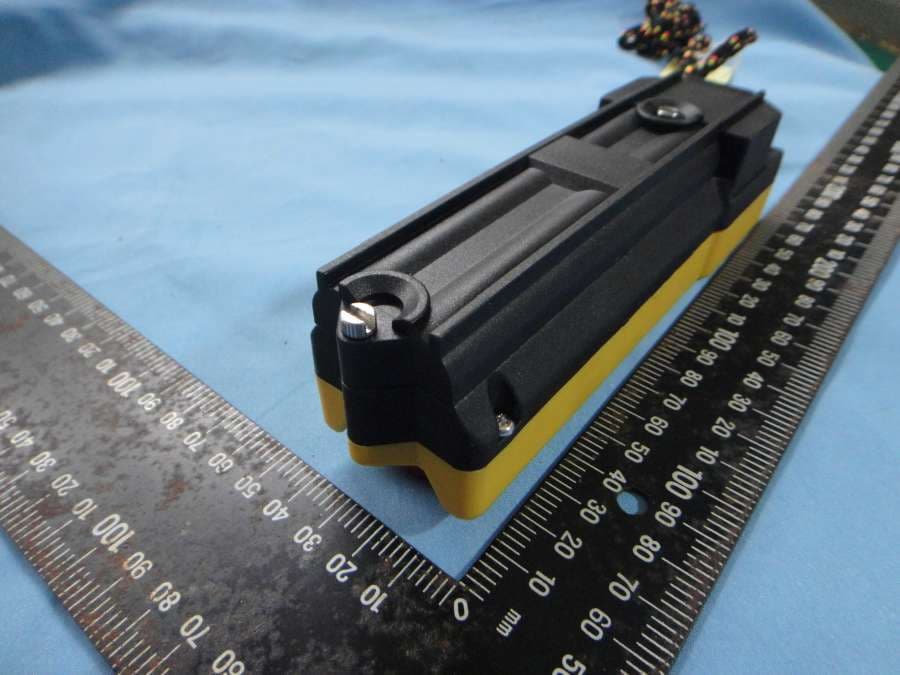
NCT12BP10
Dec 19, 2012Industrial Radio Remote Controller
Equipment Class
DXX - Part 15 Low Power Communication Device Transmitter