NCT059L40Industrial Radio Remote Controller
Gain Electronic Co Ltd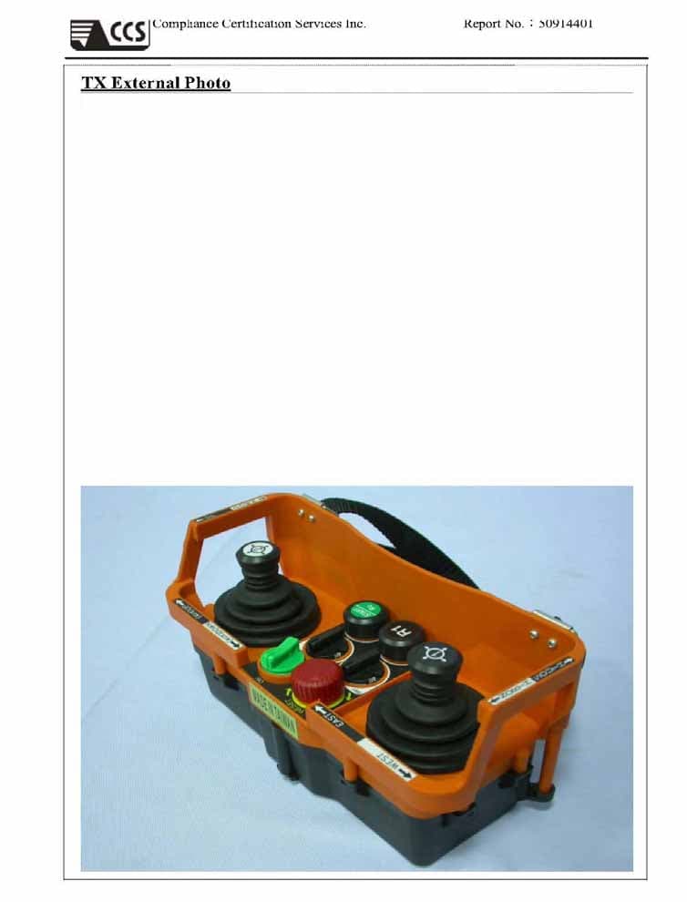
Click to zoom
Application Details
- Equipment Class
- DSC - Part 15 Security/Remote Control Transmitter
- Date of Grant
- Oct 25, 2005
- Application Purpose
- Original Equipment
- Date of Application
- Oct 25, 2005
- Equipment Note
- Industrial Radio Remote Controller
- Frequency Range
- 310.00000000 - 320.00000000
- Company
- Gain Electronic Co Ltd
- Country
- Taiwan
Documents & Files
Document Text
Text extracted from the exhibit documents filed with the FCC. Open a document above to read the original.
Users Manual
8 1 User’s Guide SAGA1-L40 Joystick type Industrial Radio Remote Controller 8 2 Contents Warranty Precautions of operation General Operation Batteries Emergency Procedures Wiring 8 1 Warranty Gain Electronic Co., Ltd. guarantees that this equipment meets its published specifications at the time of shipment from the factory. Under proper installation it should work as expected. However, GAIN does not guarantee that operation in SAGA1 system is error free or without intermission. This equipment is warranted against defects in material and manufacturing for a period of one year from the date of shipment. During the warranty period, GAIN is responsible for necessary repairs as long as the product can be proved to be defective. For warranty service or repair, this product must be returned to a service facility designated by GAIN. Buyer will pay shipping charges to GAIN, while GAIN will pay return shipping charges. This warranty does not include consumptive parts such as batteries, fuses, buttons, and relays. Also this warranty does not cover defects caused by improper installation, improper or insufficient maintenance, unauthorized modification, and improper operation, ignorance of environmental specifications, or improper software or interfacing. No other warranty is expressed or implied, except for the above mentioned. The remedies provided herein are the buyers' sole and exclusive remedies. GAIN shall not be liable for any direct, indirect, special, incidental or consequential damages. 2 Precautions of Operation 1. Please carefully read the manual before operating this device. 2. Never dismantle the equipment by any unauthorized personnel, or equipment may be damaged. 3. This manual is for reference only. Pleases consult your distributor for further assistance. 4. The equipment has been strictly tested for quality before delivery from our plant. However, this equipment must not be used in dangerous situations or where damage may result. 5. After operation, shut off main power to the crane, power to receiver, and turn the key to “OFF” position and remove it. 6. Transmitter should be placed in a safe area when not in use to avoid accidental pressing of buttons. 7. The crane should be equipped with main power relay, limit switch and other safety devices. 8. Don’t use equipment during lightening or high electrical interference conditions. 9. Make sure that the batteries are in good condition and power for receiver is correct. 10. Maintenance should only be done while the crane’s main power is off to prevent electrical shock. 11. Operating in an industrial facility is highly dangerous; therefore, operator must have adequate training in using SAGA1 system. 12. Those who operate the machine should be healthy and have good judgment in regards to safety. 13. Although the SAGA1 transmitter is very durable and weather resistant care should be taken not to expose it to severe impact or pressure. 14. If the severe interference occurred you should stop using the equipment at once.15 15. Please take the battery out when the equipment will not be used for a long time. 16. Be sure to know the “Procedures of Emergency “ 3 General Operation 1) Turn on the main power switch of the equipment (Crane). 2) Install four AA size batteries in the transmitter make sure the “+”and “-“ direction are correct. 3) Turn the rotary key switch clockwise to "ON" position, then press the Start pushbutton to Power-On. 4) Operate normally according to the function setting has done. 5) Please proceed the following procedure after operation: a) Press EMS mushroom and turn the rotary key switch of the transmitter to "OFF" position to shut off the motion of the receiver and remove the key. b) Switch off the main power switch of the equipment (Crane). c) Remove the batteries when the equipment is not going to be in use for a long period of time. SAGA1-L40 Transmitter Joystick 1 Joystick 2 Emergency Stop button Rotary Key Select Switch 1 Select Switch 2 Pushbutton (R1) Pushbutton (Start/R0) 4 Emergency Procedures In case of any emergency, please follow the steps below and ask the distributor for service immediately: 1. Press EMS mushroom. 2. Turn the rotary key to "OFF" position. 3. Shut off the main power of the Crane and discontinue the operation. 4. Contact the distributor to find out reasons. Press EMS button Turn off and remove the rotary key switch 5 Batteries Four AA size batteries are required for the transmitter. There is a 3-stage power indicating functions with LED display. “Green color”: Sufficient power to operate transmitter. ”Yellow color”: Power is depleting. Operation must be stopped immediately (for example: down the goods to ground) to replace batteries. “Red color”: Insufficient power. Transmitter will send out an emergency stop signal to the receiver due to insufficient power. Operator should avoid this situation in order to maintain the safety of operation. 6 6 Wiring FCC Caution: 1. This device complies with Part 15 of the FCC rules. Operation is subject to the following two conditions: (1) This device may not cause harmful interference, and (2) This device must accept any interference received, including interference that may cause undesired operation. 2. This device and its antenna(s) must not be co-located or operating in conjunction with any other antenna or transmitter. 3. Changes or modifications to this unit not expressly approved by the party responsible for compliance could void the user authority to operate the equipment. Remark: This product of SAGA1-L40 will apply and be sold to both the transmitter and the associated receiver unit as a "complete system"only.
External Photos
! Compliance Certification Services Inc. ! Report No.Κ50914401 ! ! ! ! ! ! !
ID Label/Location Info
Company: GAIN ELECTRONIC CO., LTD Model: SAGA1-L40 Product : Industrial Radio Remote Controller GAIN ELECTRONIC CO., LTD Model No: SAGA1-L40 FCC IDNCT059L40 This device complies with part 15 of the FCC Rules. Operation is subject to the following two conditions: [1] this device may not cause harmful interference and [2] this device must accept any interference received, including interference that may cause undesired operation. S/N Made in Taiwan Label Here
Internal Photos
! Compliance Certification Services Inc. ! Report No.Κ50914401 ! ! ! ! ! TX Internal Photo ! ! Compliance Certification Services Inc. ! Report No.Κ50914401 ! ! ! ! ! ! ! ! Compliance Certification Services Inc. ! Report No.Κ50914401 ! ! ! ! ! ! ! ! Compliance Certification Services Inc. ! Report No.Κ50914401 ! ! ! ! ! ! ! ! Compliance Certification Services Inc. ! Report No.Κ50914401 ! ! ! ! ! ! ! Compliance Certification Services Inc. ! Report No.Κ50914401 ! ! ! ! ! ! ! !
Test Report
Compliance Certification Services Inc. Report No.: 50914401-RP1 FCC ID: NCT059L40 Date of Issue: September 28, 2005 Note: This report shall not be reproduced except in full, without the written approval of Compliance Certification Services Inc. This document may be altered or revised by Compliance Certification Services Inc. personnel only, and shall be noted in the revision section of the document. FCC 47 CFR PART 15 SUBPART C TEST REPORT For Industrial Radio Remote Controller Model: SAGA1-L40 Trade Name: SAGA Issued to GAIN ELECTRONIN CO., LTD 4F-1, NO.288-5, Hsin-Ya Rd, Chien-Chen Zone(806), Kaohsiung, Taiwan, R.O.C. Issued by Compliance Certification Services Inc. No. 8, Jiu Ceng Ling, Jiaokeng Village,Sinhua Township, Tainan Hsien 712, Taiwan R.O.C. TEL: 886-6-580-2201 FAX: 886-6-580-2202 Compliance Certification Services Inc. Report No.: 50914401-RP1 FCC ID: NCT059L40 Date of Issue: September 28, 2005 Page 2 TABLE OF CONTENTS 1. TEST RESULT CERTIFICATION.....................................................................................3 2. EUT DESCRIPTION...........................................................................................................4 2.1 ANTENNA CONNECTED CONSTRUCTION................................................................................4 3. TEST METHODOLOGY....................................................................................................5 3.1 EUT CONFIGURATION......................................................................................................5 3.2 EUT EXERCISE................................................................................................................5 3.3 GENERAL TEST PROCEDURES...........................................................................................5 3.4 FCC PART 15.205 RESTRICTED BANDS OF OPERATIONS...........................................6 3.5 DESCRIPTION OF TEST MODES..........................................................................................6 4. INSTRUMENT CALIBRATION.........................................................................................7 5. FACILITIES AND ACCREDITATIONS............................................................................8 5.1 FACILITIES.....................................................................................................................8 5.2 EQUIPMENT....................................................................................................................8 5.3 LABORATORY ACCREDITATIONS AND LISTING..................................................................8 5.4 TABLE OF ACCREDITATIONS AND LISTINGS.......................................................................9 6. SETUP OF EQUIPMENT UNDER TEST.........................................................................10 6.1 SETUP CONFIGURATION OF EUT.....................................................................................10 6.2 SUPPORT EQUIPMENT....................................................................................................10 7. FCC PART 15.231 REQUIREMENTS..............................................................................11 7.1 20 DB BANDWIDTH...................................................................................................11 7.2 LIMIT OF TRANSMISSION TIME.......................................................................................14 7.3 RADIATED EMISSIONS...................................................................................................17 7.4 POWERLINE CONDUCTED EMISSIONS..............................................................................32 Compliance Certification Services Inc. Report No.: 50914401-RP1 FCC ID: NCT059L40 Date of Issue: September 28, 2005 Page 3 1. TEST RESULT CERTIFICATION Applicant GAIN ELECTRONIC CO., LTD. Address 4F-1, NO.288-5, Hsin-Ya Rd, Chien-Chen Zone (806), Kaohsiung, Taiwan, R.O.C. Equipment Under Test Industrial Radio Remote Controller Model Number SAGA1-L40 Trade Name SAGA Date of Test September .22, 2005 APPLICABLE STANDARDS STANDARD TEST RESULT FCC 47 CFR Part 15 Subpart C No non-compliance noted We hereby certify that: The above equipment was tested by Compliance Certification Services Inc. The test data, data evaluation, test procedures, and equipment configurations shown in this report were made in accordance with the procedures given in ANSI C63.4: 2003 and the energy emitted by the sample EUT tested as described in this report is in compliance with conducted and radiated emission limits of FCC Rules Part 15.207, 15.209 and Part 15.231. The test results of this report relate only to the tested sample identified in this report. Approved by: Reviewed by: Alex Chiu Jeter Wu Manager Section Manager Compliance Certification Services Inc. Compliance Certification Services Inc. Compliance Certification Services Inc. Report No.: 50914401-RP1 FCC ID: NCT059L40 Date of Issue: September 28, 2005 Page 4 2. EUT DESCRIPTION Product Industrial Radio Remote Controller Model Number SAGA1-L40 Model Difference N/A Trade Name SAGA Power Supply Powered by battery (Rating: 6Vdc) Frequency Range 310MHz ~ 320MHz Maximum Emission Level 310MHz : 69.80 (dBV/M) 320MHz : 70.90 (dBV/M) Modulation Technique FSK Modulation Antenna Designation Dipole Antenna 1.5 dBi Remark: This submittal(s) (test report) is intended for FCC ID:NCT059L40 filing to comply with Section 15.207, 15.209 and 15.231 of the FCC Part 15, Subpart C Rules. 2.1 Antenna Connected Construction The antenna used in this product. The transmitter device uses a wire dipole and the receiver device uses a helix antenna. And the maximum Gain of the antenna is only 1.5dBi. Compliance Certification Services Inc. Report No.: 50914401-RP1 FCC ID: NCT059L40 Date of Issue: September 28, 2005 Page 5 3. TEST METHODOLOGY The tests documented in this report were performed in accordance with ANSI C63.4 (2001) and FCC CFR 47 2.1046, 2.1047, 2.1049, 2.1051, 2.1053, 2.1055, 2.…
Text truncated - open the document above for the full version.
Test Setup Photos
Compliance Certification Services Inc. Report No.: 50914401-RP1 FCC ID: NCT059L40 Date of Issue: September 28, 2005 Page 36 APPENDIX 1 PHOTOGRAPHS OF TEST SETUP Radiated Emission Set up Photos (1) X-axis Compliance Certification Services Inc. Report No.: 50914401-RP1 FCC ID: NCT059L40 Date of Issue: September 28, 2005 Page 37 Compliance Certification Services Inc. Report No.: 50914401-RP1 FCC ID: NCT059L40 Date of Issue: September 28, 2005 Page 38 (2) Y-axis Compliance Certification Services Inc. Report No.: 50914401-RP1 FCC ID: NCT059L40 Date of Issue: September 28, 2005 Page 39 Compliance Certification Services Inc. Report No.: 50914401-RP1 FCC ID: NCT059L40 Date of Issue: September 28, 2005 Page 40 (3) Z-axis Compliance Certification Services Inc. Report No.: 50914401-RP1 FCC ID: NCT059L40 Date of Issue: September 28, 2005 Page 41
Test Setup Photos
Compliance Certification Services Inc. Report No.: 50914401-RP1 FCC ID: NCT059L40 Date of Issue: September 28, 2005 Page 33 APPENDIX 1 PHOTOGRAPHS OF TEST SETUP Radiated Emission Set up Photos (1) X-axis Compliance Certification Services Inc. Report No.: 50914401-RP1 FCC ID: NCT059L40 Date of Issue: September 28, 2005 Page 34 Compliance Certification Services Inc. Report No.: 50914401-RP1 FCC ID: NCT059L40 Date of Issue: September 28, 2005 Page 35 (2) Y-axis Compliance Certification Services Inc. Report No.: 50914401-RP1 FCC ID: NCT059L40 Date of Issue: September 28, 2005 Page 36 Compliance Certification Services Inc. Report No.: 50914401-RP1 FCC ID: NCT059L40 Date of Issue: September 28, 2005 Page 37 (3) Z-axis Compliance Certification Services Inc. Report No.: 50914401-RP1 FCC ID: NCT059L40 Date of Issue: September 28, 2005 Page 38
Contact Information
Applicant
Mr.Danny Lin(Marketing Director)
Test Firm
Compliance Certification Services Inc.Paul Liau
Technical Specifications
| # | Rule Parts | Frequency Range | Power Output |
|---|---|---|---|
| 1 | 15.231 | 310 MHz - 320 MHz | - |
Other Applications from Gain Electronic Co Ltd
NCT137V6R
Aug 25, 2013Industrial Radio Remote Controller
Equipment Class
DXX - Part 15 Low Power Communication Device Transmitter
NCT137V6T
Aug 25, 2013Industrial Radio Remote Controller
Equipment Class
DXX - Part 15 Low Power Communication Device Transmitter
NCT12CP40
Feb 10, 2013Industrial Radio Remote Controller
Equipment Class
DXX - Part 15 Low Power Communication Device Transmitter
NCT12CT8
Feb 10, 2013Industrial Radio Remote Controller
Equipment Class
DXX - Part 15 Low Power Communication Device Transmitter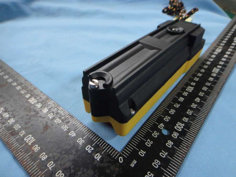
NCT12BP10
Dec 19, 2012Industrial Radio Remote Controller
Equipment Class
DXX - Part 15 Low Power Communication Device Transmitter