NCYM5800SFSUD2Wireless Internet Access Subscriber Unit
Trango Systems Inc
Click to zoom
Application Details
- Equipment Class
- DTS - Digital Transmission System
- Date of Grant
- Jun 19, 2005
- Application Purpose
- Original Equipment
- Date of Application
- Jun 19, 2005
- Equipment Note
- Wireless Internet Access Subscriber Unit
- Frequency Range
- 5736.00000000 - 5836.00000000
- Company
- Trango Systems Inc
- Country
- United States
Documents & Files
Document Text
Text extracted from the exhibit documents filed with the FCC. Open a document above to read the original.
Users Manual
Access5830™ Wireless Broadband System USER MANUAL June 15, 2005 Revision G For M5830S Firmware Version 1.12 and TrangoFOX Firmware Version 1.05 Table of Contents Trango Trango Broadband Wireless — Access5830 User Manual Rev. G page ii Table of Contents Preface iv FCC Information ....................................................................................................................................................... iv Warranty Information ................................................................................................................................................ iv Section 1 Introduction 1 Overview .................................................................................................................................................................... 1 SmartPolling™ Overview .......................................................................................................................................... 1 Section 2 Hardware Overview 2 Access5830 Radio Types............................................................................................................................................ 2 Access5830 AP and SU Hardware Components ........................................................................................................ 4 FOX Series Subscriber Units Hardware Components ................................................................................................ 5 Section 3 Getting Started 7 Connections and Power .............................................................................................................................................. 7 Opmode and Radio Management Concepts................................................................................................................ 7 Browser Interface ....................................................................................................................................................... 8 Command Line Interface .......................................................................................................................................... 10 Telnet.................................................................................................................................................................... 10 Troubleshooting.................................................................................................................................................... 10 Reset Button on FOX Series Radios..................................................................................................................... 11 Serial Port on M5830 Series Radios ..................................................................................................................... 11 Section 4 Basic Configuration via Browser Interface 12 Configuring AP’s Subscriber Unit Database ............................................................................................................ 12 Configure Other Basic AP Parameters ..................................................................................................................... 14 Configure Basic SU Parameters ............................................................................................................................... 16 LED Summary.......................................................................................................................................................... 17 Evaluate Link Quality............................................................................................................................................... 17 RF Link Loopback Test ............................................................................................................................................ 18 SU Ranging / RSSI Test ........................................................................................................................................... 18 Advanced Setup Page ............................................................................................................................................... 19 Other Key Parameters............................................................................................................................................... 20 Site Survey Page....................................................................................................................................................... 21 Section 5 Basic Configuration via CLI 22 Access Point Basic Settings...................................................................................................................................... 22 Subscriber Unit Basic Settings ................................................................................................................................. 25 Subscriber Unit Database (SUDB) Settings ............................................................................................................. 27 Section 6 Mounting Hardware 28 M5830 Series Radios (Access Points and Subscriber Units) .................................................................................... 28 FOX Series Radio Hardware and Mounting ............................................................................................................. 30 Cabling and Grounding Considerations.................................................................................................................... 32 Weatherizing............................................................................................................................................................. 34 Section 7 Deployment 35 Site Selection ............................................................................................................................................................ 35 Site Survey ..................................................................................................................…
Text truncated - open the document above for the full version.
Cover Letter(s)
15070 Avenue of Science, Suite 200 San Diego, CA 92128 Ph: 858-653-3900 Fax: 858-621-2725 Federal Communications Commission Authorization and Evaluation Division Confidentiality Request regarding application for certification of: FCC ID: NCYM5800SFSUD2 Pursuant to Sections 0.457 and 0.459 of the Commission’s Rules, we hereby request confidential treatment of information accompanying this application as outlined below: Schematic Block Diagram The above materials contain trade secrets and proprietary information not customarily released to the public. The public disclosure of these materials may be harmful to the applicant and provide unjustified benefits to its competitors. The applicant understands that pursuant to Section 0.457 of the Rules, disclosure of this application and all accompanying documentation will not be made before the date of the Grant for this application. Sincerely, Achim Soelter RF Engineering Manager Trango Systems, Inc.
Cover Letter(s)
15070 Avenue of Science, Suite 200 San Diego, CA 92128 Ph: 858-653-3900 Fax: 858-621-2725 June 6, 2005 Federal Communications Commission Authorization and Evaluation Division Equipment Authorization Branch 7435 Oakland Mills Road Columbia, MD 21046 To whom it may concern: We, Trango Systems, Inc., hereby authorize Compliance Certification Services, to act as our agent in all matters relating to applications for equipment authorization, including the signing of all documents relating to these matters. Any and all acts carried out by Compliance Engineering Service, Inc. on our behalf shall have the same effect as acts of our own. I hereby certify that the we are not subject to a denial of Federal benefits, that includes FCC benefits, pursuant to Section 5301 of the Anti-Drug Abuse Act of 1988, 21 U.S.C. Section 853(a). This authorization expires on December 31, 2005 Sincerely, Achim Soelter Achim Soelter RF Engineering Manager Phone – 858-653-3900 Fax – 858-621-2725
Cover Letter(s)
1 Helen Zhao Subject:FW: TRANGO SYSTEMS, INC., FCC ID: NCY5800SFSUD2, Assessment NO.: AN05T4856, Notice#1 From: Danielle Zhan Sent: Monday, June 20, 2005 11:55 AM To:Helen Zhao Cc:Barbara Judge; Michael Heckrotte; Mike Kuo Subject:RE: TRANGO SYSTEMS, INC., FCC ID: NCY5800SFSUD2, Assessment NO.: AN05T4856, Notice#1 Dear Helen, Please find answers to your questions as below in blue. Thanks for your further review. Danielle Zhan -----Original Message----- From: Helen Zhao Sent: Wednesday, June 15, 2005 3:28 PM To: Danielle Zhan Cc: Barbara Judge; Michael Heckrotte; Mike Kuo Subject: RE: TRANGO SYSTEMS, INC., FCC ID: NCY5800SFSUD2, Assessment NO.: AN05T4856, Notice#1 Dear Danielle, Please answer the following questions: Question #1: The user manual indicates the manual applies to a total of six series products and six model names and associated FCC IDs are listed on the manual, but none of them relates to this filing. Please add necessary information for the newly added model in this filing, please update model difference table, also specify the antenna that can be used with the new model. [Danielle] User manual has been updated with the new model and its FCC ID added in, please see attached. UserManual.FSU-D2 .pdf Question #2: FCC ID label format does not include FCC15.19 compliance statement. According to FCC TCB traing material (see attachment), when the device is larger than palm size (10x8cm), then the statement must be on the label. Your device's size is 6" x 3", which is 15x7.6cm, please revise the FCC ID label format to include the compliance statement. [Danielle] A label that shows the FCC15.19 compliance statement has been provided as part of the labeling format, please find revised Label Format and Location file as attached. FCC ID Label Format and Locati... Question #3: The user manual and product specification all indicate that the device is operating from 5736MHz to 5836MHz. 2 However the test report shows investigation was done for 5745-5825MHz only, which is not sufficient to demonstrate compliance. Please redo the all the test at low and high channels. [Danielle] Additional tests were performed to cover the investigated frequency from 5736 MHz to 5836 MHz, and related data has been revised based on additional tests. Please see revised test report as attached. 05U3457 FCC DTS Report. revise... Question #4: The antenna specification indicates the patch antenna has a gain of 25dBi, but the test report refers to 24dBi (page 6 & 19), please correct it to keep consistent. [Danielle] The antenna gain has been revised to 25 dBi in the test report, please see the revised report as attached above. Question #5: There are two test configurations, but the test report shows one test setup diagram, please add one more for stand along configuration (using internal antenna). [Danielle] A setup diagram for the stand-alone configuration has been added in the report, same as attached above. Question #6: Please update external photos to include power supply and J-Box. [Danielle] See attached updated External Photos file which include external photos for the power supply and J-Box. External Photos.pdf Question #7: The internal photos cover only one PCB board, please provide more photos to see the internal structure of the subscribe unit. Please show position of internal antenna as well. [Danielle] Some more photos are taken to satisfy this requirement, please see attached Internal Photos file. Internal Photos.pdf Best Regards, Helen Zhao The items indicated above must be submitted before processing can continue on the above referenced application. Failure to provide the requested information within 30 days of the original e-mail date may result in application dismissal and forfeiture of the filing fee. Also, please note that partial responses increase processing time and should not be submitted. Any questions about the content of this correspondence should be directed to the e-mail address listed below the name of the sender.
ID Label/Location Info
LABEL SPECIFICATION PRODUCT: M5800S-FSU-D2 This specification shows the format of the regulatory label. 1) Label size is .5 inch high by 1 inch long. This specification shows the format of the FCC Statement label. 1) Label size is 1 inch high by 2 inch long. 2) Label is to be printed on LB-9018. Regulatory Label FCC Statement Label
Operational Description
15070 Avenue of Science, Suite 200 San Diego, CA 92128 Ph: 858-653-3900 Fax: 858-621-2725 Federal Communications Commission Authorization and Evaluation Division SYSTEM DESCRIPTION M5800S-FSU-D2 FCC ID: NCYM5800SFSUD2 The M5800S-FSU-D2 subscriber unit (SU) is a wireless point to point digital spread spectrum data transceiver which, when setup in a cell having at least one access point (AP), functions as a wireless MAC layer Ethernet access solution. Each SU communicates with a unique AP using 5.8 GHz spread spectrum technology. The SU accepts full or half duplex Ethernet IEE 802.3 data packets from a 10/100BaseT port, breaks the packets into smaller packets, and transmits them at 11 Mbit/sec rate over the air. The unit only transmits packets when given a grant to do so by the AP. The SU utilizes a dish antenna to achieve long range and a narrow radio beamwidth or an internal antenna. The RF power level is controlled by the AP and will be reduced automatically when the SU is near the AP unit. Sincerely, Achim Soelter Achim Soelter RF Engineering Manager Trango Systems, Inc.
Operational Description
Product Specification: 710-9767 Rev B 5.8 GHz Spread Spectrum Broadband Wireless Internet Access Subscriber Unit Model: M5800S-FSU M5800S-FSU-D M5800S-FSU-D2 August 12, 2004 ENGINEERING: MARKETING: DATE: DATE: 1.0 SUMMARY This document details the functional and parametric requirements for the FOX tm subscriber unit (FSU) transceiver which, when setup in a cell having at least one access point (AP), functions as a wireless MAC layer Ethernet access solution. Each SU communicates with a unique AP using 5.8 GHz spread spectrum technology. The SU accepts full or half duplex Ethernet IEEE 802.3 data packets from a 10/100BaseT port, adds header information, scrambles the data and transmits them at 11 Mbit/sec rate over the air. The Subscriber Unit product consists of the following: - 1 subscriber unit (SU) with integrated patch antenna - 1 Pole/wall mount - 1 Junction/Power adapter 2.0 FUNCTIONAL REQUIREMENTS The paragraphs below describe the functional requirements of the transceiver. 2.1.1 GENERAL REQUIREMENTS The unit shall be designed to be compliant with FCC part 15.247 intentional radiator requirements for a point to point system, and 15.109 unintentional radiator requirements. This requirement specifies certain maximum RF power output and spurious emissions levels. The unit shall also be compliant with ETSI EMC standards as outlined in the Parametric Specifications section. The unit shall be designed for installation by a professional installer or the end customer. The M5800s-FSU-D2 can also be used without a dish reflector. 2.1.2 HARDWARE REQUIREMENTS 2.1.2.1 User Controls and Indicators 2.1.2.1.1 LEDs LED operational requirements are given below. It should be noted, however, that in “Survey” mode, no LEDs shall light up except the LNKST and ACTST LEDs. The unit shall have LED indicators to indicate the following: a) NET LED Green: Illuminated when network connection is made, regardless of whether it is 10BaseT or 100 BaseT (LNKST) b) ACT LED Green: Receive/Transmit Status (ACTST) for Ethernet port c) RSSI LEDs (4) In all modes except “Survey”, the unit’s four yellow LEDs shall indicates the level of RF signal being received from a valid AP. Yellow LED 1 (leftmost): On when RSSI is greater or equal to –80 dBm Yellow LED 2 : On when RSSI is greater or equal to –75 dBm Yellow LED 3 : On when RSSI is greater or equal to –70 dBm Yellow LED 4 (rightmost): On when RSSI is greater or equal to –65 dBm. If a signal no signal is detected the LEDs will not be on at all. The LED shall be controlled by the FPGA and is based upon the Prism RSSI register, which indicate the energy level on the antenna. d) Association LED(green): Blinking at: 1) Once every second when unit is powered on but opmode is OFF 2) Twice per second while in SU opmode and scanning for an AP 3) Solid after unit is associated with an AP. 2.1.2.1.2 Connectors The unit shall have a connector for a 10/100 Base T shielded twisted pair (STP) interface cable connection. The unit shall be powered using the unused twisted pair wires. 2.1.2.2 Power Input The unit shall have provisions to operate from an unregulated DC power supply. This input shall be reverse voltage polarity protected and have filtering to prevent damage from static caused by typical nearby lightning strikes and the human body ESD model. The unit shall have automatically resetting fusing provisions in the event of an over current condition. 2.1.2.3 Digital Section 2.1.2.3.1 Microprocessor Subsystem The unit shall utilize a 32 bit RISC microprocessor to accomplish the requirements in the software section. The subsystem shall consist of the following hardware functions: 1) 32 Bit Microprocessor with SDRAM controller and Ethernet MAC interface 2) Ethernet PHY interface 3) TTL level Serial port for debug purposes 4) Nonvolatile, writeable FLASH Memory – 512Kbyte 5) SDRAM 8 Mbytes 2.1.2.3.2 Field Programmable Gate Array (FPGA) A field programmable gate array shall be used to accomplish the following functions: 1) 32 bit wide, 256 long word deep, full duplex FIFO for RF MAC packet transfer to and from the microprocessor subsystem to the radio section Baseband Processor (BBP) 2) Microprocessor subsystem data bus interface for transferring data between the microprocessor and the FPGA 3) Shift register for to convert RF MAC packets going between the FIFO and the BBP from parallel to serial format. 4) PLL programming for IF and RF local oscillators. 5) TX/RX switch processing. 6) BBP register read/write 7) JTAG interfacing to test equipment 8) Ranging response processing 9) Polling response processing 10) Timer to support CPU 11) RSSI LED support 12) Antenna switch control (polarization) 2.1.2.3.3 Baseband Processor (BBP), Modulator and Demodulator The unit shall use the Intersil Prism II chipset solution for modulating and demodulating RF MAC layer packets onto the RF channel. The portion of the chipset that shall be used consists of the BBP and the Quadrature Modulator/Demodulator. Functions of the solution that shall be utilized: 1) Data Transmit 2) Data Receive 3) Data scrambling. 4) IF AGC 5) Received Signal Strength monitoring 6) Clear Channel Assessment. 7) RF power output adjustment 2.1.2.4 RF/Analog Section The unit RF section shall be designed as a half duplex transceiver. The unit shall use a double-conversion receiver architecture. The unit shall have provisions for multilevel power control at the IF to mitigate the near-far problem encountered during subscriber setup. The unit shall have provisions to control the power output over temperature based on the AP temperature and periodic power leveling. The unit shall have provisions for sending accurate signal strength measurement to the microprocessor and FPGA. 2.1.2.5 Packaging/Mounting The packaging shall be designed for outdoor operation in 100 % humidity conditions. The packaging shall be designed for outdoor pole or wall mounting with grounding provisions. The packaging shall be designed to comply with EMC standar…
Text truncated - open the document above for the full version.
Parts List/Tune Up Info
3.5 INTEGRATED ANTENNA Type: Patch Array Antenna Polarization: Vertical, Horizontal electrically selectable Frequency: 5.2 to 5.9 GHz 5.7 to 5.9 GHz for the D2 Gain: +15 +/- 1 dBiL +8 +/- 1 dBiL for the Fox-D2 Az Beamwidth: 32 degrees (3 dB down) 60 degrees (3 dB down) for the Fox-D2 El Beamwidth: 18 degrees (3 dB down) 60 degrees (3 dB down) for the Fox-D2 Cross Pol: >15 dB Front/Back Ratio: >30 DB as mounted in M5800S-FSU VSWR: < 2.0:1 over Bandwidth 3.6 Dish Antenna (18 inch DSS style) The unit is designed to operate with the Trango Broadband model AD5800-25 dual linear polarized dish antenna. Type: 18” DSS Style Dish Antenna Polarization: Vertical, Horizontal electrically selectable Frequency: 5.7 to 5.9 GHz Gain: +25 dBi when M5800S-FSU-D or M5800S-FSU-D2 is installed on dish Az Beamwidth: 9° El Beamwidth: 9° Cross Pol: > 15dB Front/Back Ratio: > 30dB VSWR: 2:1 Wind Loading: 80 mph operational 15070 Avenue of Science, Suite 200 San Diego, CA 92128 Ph: 858-653-3900 Fax: 858-621-2725 Federal Communications Commission Authorization and Evaluation Division Regarding the AD5800-25-D reflector dish used with the M5800S-FSU-D2 transceiver: FCC ID: NCYM5800SFSUD2 Pursuant to Sections 15.203 requirement for use of a unique antenna connection or integral antenna, the reflector used in this design is not a standard DSS dish antenna available off-the- shelf. The antenna is custom made for Trango Systems and uses a custom designed boom which places the transceiver feed element at the focal point of the dish. If a standard DSS dish antenna were used, the focal point will not be centered on the feed element and the dish would not function properly. Please contact me at (858) 353-3900 if you have any further concerns. Sincerely, Achim Soelter Achim Soelter RF Engineering Manager Trango Systems, Inc.
Test Report
FCC CFR47 PART 15 SUBPART C CERTIFICATION TEST REPORT FOR WIRELESS INTERNET ACCESS SUBSCRIBR UNIT MODEL NUMBER: M5800S-FSU-D2 FCC ID: NCYM5800SFSUD2 REPORT NUMBER: 05U3457 ISSUE DATE: JUNE 15, 2005 Prepared for TRANGO SYSTEMS, INC. 15070 AVENUE OF SCIENCE, SUITE 200 SAN DIEGO, CA 92128 U.S.A. Prepared by COMPLIANCE ENGINEERING SERVICES, INC. d.b.a. COMPLIANCE CERTIFICATION SERVICES 561F MONTEREY ROAD, MORGAN HILL, CA 95037, USA TEL: (408) 463-0885 FAX: (408) 463-0888 * REPORT NO: 05U3457 DATE: JUNE 15, 2005 EUT: WIRELESS INTERNET ACCESS SUBSCRIBR UNIT FCC ID: NCYM5800SFSUD2 Page 2 of 62 COMPLIANCE CERTIFICATION SERVICES DOCUMENT NO: CCSUP4031A 561F MONTEREY ROAD, MORGAN HILL, CA 95037 USA TEL: (408) 463-0885 FAX: (408) 463-0888 This report shall not be reproduced except in full, without the written approval of CCS. Revision History Rev. Issue Date Revisions Revised By A Initial Issue YZ REPORT NO: 05U3457 DATE: JUNE 15, 2005 EUT: WIRELESS INTERNET ACCESS SUBSCRIBR UNIT FCC ID: NCYM5800SFSUD2 Page 3 of 62 COMPLIANCE CERTIFICATION SERVICES DOCUMENT NO: CCSUP4031A 561F MONTEREY ROAD, MORGAN HILL, CA 95037 USA TEL: (408) 463-0885 FAX: (408) 463-0888 This report shall not be reproduced except in full, without the written approval of CCS. TABLE OF CONTENTS 1. ATTESTATION OF TEST RESULTS............................................................................................. 4 2. TEST METHODOLOGY .................................................................................................................. 5 3. FACILITIES AND ACCREDITATION .......................................................................................... 5 4. CALIBRATION AND UNCERTAINTY ......................................................................................... 5 4.1. MEASURING INSTRUMENT CALIBRATION ............................................................................. 5 4.2. MEASUREMENT UNCERTAINTY ............................................................................................... 5 5. EQUIPMENT UNDER TEST ...........................................................................................................6 5.1. DESCRIPTION OF EUT ..............................................................................................................6 5.2. MAXIMUM OUTPUT POWER .................................................................................................... 6 5.3. DESCRIPTION OF AVAILABLE ANTENNAS ............................................................................. 6 5.4. SOFTWARE AND FIRMWARE .................................................................................................... 6 5.5. WORST-CASE CONFIGURATION AND MODE......................................................................... 6 5.6. DESCRIPTION OF TEST SETUP ................................................................................................ 7 6. TEST AND MEASUREMENT EQUIPMENT .............................................................................. 10 7. LIMITS AND RESULTS ................................................................................................................. 11 7.1. CHANNEL TESTS FOR THE 5725 TO 5850 MHz BAND ......................................................... 11 7.1.1. 6 dB BANDWIDTH ........................................................................................................... 11 7.1.2. 99% BANDWIDTH............................................................................................................ 15 7.1.3. PEAK OUTPUT POWER .................................................................................................. 19 7.1.4. MAXIMUM PERMISSIBLE EXPOSURE ........................................................................ 24 7.1.5. AVERAGE POWER........................................................................................................... 27 7.1.6. PEAK POWER SPECTRAL DENSITY ............................................................................ 28 7.1.7. CONDUCTED SPURIOUS EMISSIONS.......................................................................... 32 7.2. RADIATED EMISSIONS.............................................................................................................39 7.2.1. TRANSMITTER RADIATED SPURIOUS EMISSIONS ................................................. 39 7.2.2. TRANSMITTER ABOVE 1 GHz FOR 5725 TO 5850 MHz BAND WITH STAND-ALONE CONFIGURATION .............................................................................................. 42 7.2.3. TRANSMITTER ABOVE 1 GHz FOR 5725 TO 5850 MHz BAND WITH REFLECTTOR CONFIGURATION ................................................................................................. 43 7.2.5 WORST-CASE CONFIGURATION RADIATED EMISSIONS BELOW 1 GHz, .......... 44 7.2.5.1 ANTENNA SET AS HORIZONTAL POLARIZATION .................................................. 44 7.2.5.2 ANTENNA SET AS VERTICAL POLARIZATION ........................................................ 48 7.3. POWERLINE CONDUCTED EMISSIONS ................................................................................ 52 8. SETUP PHOTOS .............................................................................................................................. 56 REPORT NO: 05U3457 DATE: JUNE 15, 2005 EUT: WIRELESS INTERNET ACCESS SUBSCRIBR UNIT FCC ID: NCYM5800SFSUD2 Page 4 of 62 COMPLIANCE CERTIFICATION SERVICES DOCUMENT NO: CCSUP4031A 561F MONTEREY ROAD, MORGAN HILL, CA 95037 USA TEL: (408) 463-0885 FAX: (408) 463-0888 This report shall not be reproduced except in full, without the written approval of CCS. 1. ATTESTATION OF TEST RESULTS COMPANY NAME: TRANGO SYSTEMS, INC. 15070 AVENUE OF SCIENCE, SUITE 200 SAN DIEGO, CA 92128 EUT DESCRIPTION: WIRELESS INTERNET ACCESS SUBSCRIBR UNIT MODEL: M5800S-FSU-D2 SERIAL NUMBER: 01350006 DATE TESTED: MAY 26 ~ JUNE 1, 2005 APPLICABLE STANDARDS STANDARD TEST RESULTS FCC PART 15 SUBPART C NO NON-COMPLIANCE NOT…
Text truncated - open the document above for the full version.
Test Setup Photos
REPORT NO: 05U3457 DATE: JUNE 2, 2005 EUT: WIRELESS INTERNET ACCESS SUBSCRIBR UNIT FCC ID: NCYM5800SFSUD2 Page 55 of 61 COMPLIANCE CERTIFICATION SERVICES DOCUMENT NO: CCSUP4031A 561F MONTEREY ROAD, MORGAN HILL, CA 95037 USA TEL: (408) 463-0885 FAX: (408) 463-0888 This report shall not be reproduced except in full, without the written approval of CCS. 8. SETUP PHOTOS ANTENNA PORT CONDUCTED RF MEASUREMENT SETUP ANTENNA PORT CONDUCTED PHOTO REPORT NO: 05U3457 DATE: JUNE 2, 2005 EUT: WIRELESS INTERNET ACCESS SUBSCRIBR UNIT FCC ID: NCYM5800SFSUD2 Page 56 of 61 COMPLIANCE CERTIFICATION SERVICES DOCUMENT NO: CCSUP4031A 561F MONTEREY ROAD, MORGAN HILL, CA 95037 USA TEL: (408) 463-0885 FAX: (408) 463-0888 This report shall not be reproduced except in full, without the written approval of CCS. RADIATED RF MEASUREMENT SETUP, STAND ALONE RADIATED FRONT PHOTO REPORT NO: 05U3457 DATE: JUNE 2, 2005 EUT: WIRELESS INTERNET ACCESS SUBSCRIBR UNIT FCC ID: NCYM5800SFSUD2 Page 57 of 61 COMPLIANCE CERTIFICATION SERVICES DOCUMENT NO: CCSUP4031A 561F MONTEREY ROAD, MORGAN HILL, CA 95037 USA TEL: (408) 463-0885 FAX: (408) 463-0888 This report shall not be reproduced except in full, without the written approval of CCS. RADIATED BACK PHOTO REPORT NO: 05U3457 DATE: JUNE 2, 2005 EUT: WIRELESS INTERNET ACCESS SUBSCRIBR UNIT FCC ID: NCYM5800SFSUD2 Page 58 of 61 COMPLIANCE CERTIFICATION SERVICES DOCUMENT NO: CCSUP4031A 561F MONTEREY ROAD, MORGAN HILL, CA 95037 USA TEL: (408) 463-0885 FAX: (408) 463-0888 This report shall not be reproduced except in full, without the written approval of CCS. RADIATED RF MEASUREMENT SETUP, WITH REFLECTOR RADIATED FRONT PHOTO REPORT NO: 05U3457 DATE: JUNE 2, 2005 EUT: WIRELESS INTERNET ACCESS SUBSCRIBR UNIT FCC ID: NCYM5800SFSUD2 Page 59 of 61 COMPLIANCE CERTIFICATION SERVICES DOCUMENT NO: CCSUP4031A 561F MONTEREY ROAD, MORGAN HILL, CA 95037 USA TEL: (408) 463-0885 FAX: (408) 463-0888 This report shall not be reproduced except in full, without the written approval of CCS. RADIATED BACK PHOTO REPORT NO: 05U3457 DATE: JUNE 2, 2005 EUT: WIRELESS INTERNET ACCESS SUBSCRIBR UNIT FCC ID: NCYM5800SFSUD2 Page 60 of 61 COMPLIANCE CERTIFICATION SERVICES DOCUMENT NO: CCSUP4031A 561F MONTEREY ROAD, MORGAN HILL, CA 95037 USA TEL: (408) 463-0885 FAX: (408) 463-0888 This report shall not be reproduced except in full, without the written approval of CCS. POWERLINE CONDUCTED EMISSIONS MEASUREMENT SETUP LINE CONDUCTED FRONT PHOTO REPORT NO: 05U3457 DATE: JUNE 2, 2005 EUT: WIRELESS INTERNET ACCESS SUBSCRIBR UNIT FCC ID: NCYM5800SFSUD2 Page 61 of 61 COMPLIANCE CERTIFICATION SERVICES DOCUMENT NO: CCSUP4031A 561F MONTEREY ROAD, MORGAN HILL, CA 95037 USA TEL: (408) 463-0885 FAX: (408) 463-0888 This report shall not be reproduced except in full, without the written approval of CCS. END OF REPORT LINE CONDUCTED B…
Text truncated - open the document above for the full version.
Contact Information
Applicant
Christopher A Gustaf(VP, Engineering)
Test Firm
Compliance Certification Services IncSteve Cheng
Technical Specifications
| # | Rule Parts | Frequency Range | Power Output |
|---|---|---|---|
| 1 | 15C | 5.74 GHz - 5.84 GHz | 509.00 mW |
Other Applications from Trango Systems Inc
NCY-A600
Jan 28, 2015Altum AC600
Equipment Class
JBP - Part 15 Class B Computing Device Peripheral
NCY-SL24
Feb 05, 201324 GHz Wireless Point to Point Data Transmission System
Equipment Class
DXX - Part 15 Low Power Communication Device Transmitter
NCYP5055M
Sep 25, 2007802.11 a Point to Point Transceiver
Equipment Class
DTS - Digital Transmission System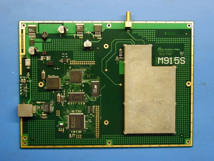
NCYM915S
Jan 16, 2006900 MHz Transceiver
Equipment Class
DTS - Digital Transmission System
NCYM5580MFSU
Jan 02, 2006Wireless Internet Access Subscriber Unit
Equipment Class
DTS - Digital Transmission System