NCYM915S900 MHz Transceiver
Trango Systems Inc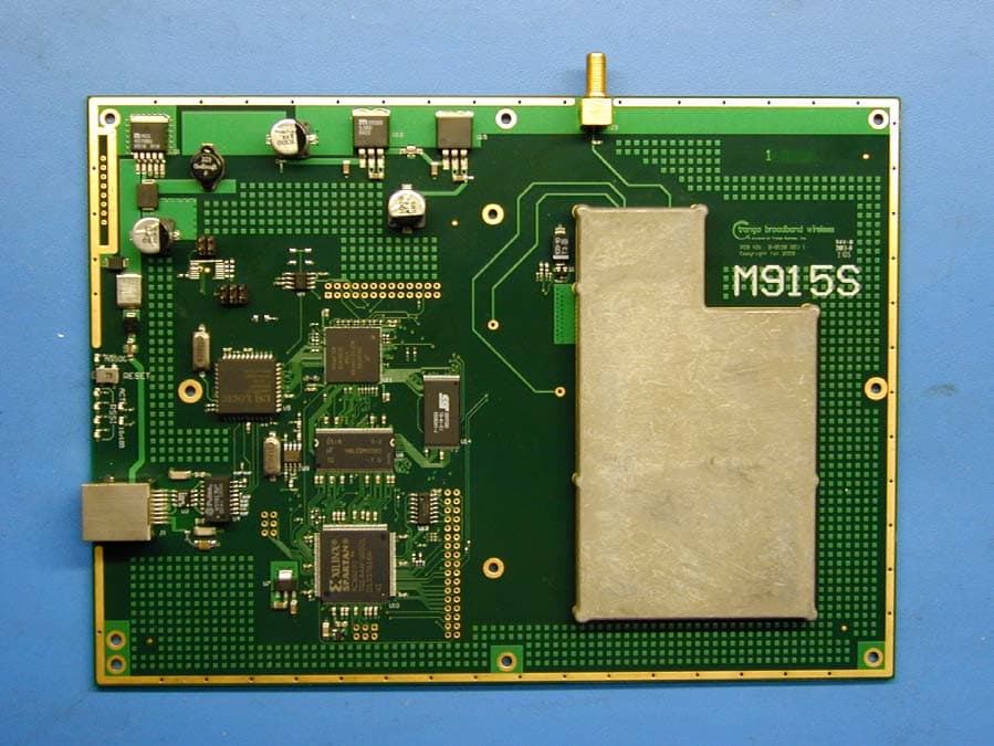
Click to zoom
Application Details
- Equipment Class
- DTS - Digital Transmission System
- Date of Grant
- Jan 16, 2006
- Application Purpose
- Original Equipment
- Date of Application
- Jan 16, 2006
- Equipment Note
- 900 MHz Transceiver
- Frequency Range
- 906.00000000 - 924.00000000
- Company
- Trango Systems Inc
- Country
- United States
Documents & Files
Document Text
Text extracted from the exhibit documents filed with the FCC. Open a document above to read the original.
Users Manual
M915S™ 900 MHz Wireless Broadband System USER MANUAL December 15, 2005 Revision A for Firmware Version 2.0 Table of Contents Trango Trango Broadband Wireless — M900S User Manual Rev. C page ii Table of Contents Preface ........................................................................................................................................................................... iv FCC Information ....................................................................................................................................................... iv Warranty Information ................................................................................................................................................ iv Firmware Notifications .............................................................................................................................................. iv Section 1 Introduction..................................................................................................................................................... 1 Overview .................................................................................................................................................................... 1 SmartPolling™ & Bandwidth Throttling.................................................................................................................... 2 Auto-retransmit Feature (ARQ).................................................................................................................................. 2 Section 2 Hardware Overview ........................................................................................................................................ 3 M915S AP and SU Hardware Components................................................................................................................ 3 Section 3 Getting Started ................................................................................................................................................ 4 Connections and Power .............................................................................................................................................. 4 Radio Management Concepts ..................................................................................................................................... 5 Browser Interface ....................................................................................................................................................... 6 Command Line Interface ............................................................................................................................................ 8 Telnet...................................................................................................................................................................... 8 Troubleshooting...................................................................................................................................................... 9 Section 4 Basic Configuration via Browser Interface ................................................................................................... 10 Configuring the AP’s Subscriber Unit Database (SUDB) ........................................................................................ 10 Configure Other Basic AP Parameters ..................................................................................................................... 12 Configure Basic SU Parameters ............................................................................................................................... 14 LED Summary.......................................................................................................................................................... 15 RF Link Loopback Test ............................................................................................................................................ 16 SU Ranging Test....................................................................................................................................................... 17 Advanced Setup Page ............................................................................................................................................... 17 Other Key Parameters............................................................................................................................................... 18 Site Survey Page....................................................................................................................................................... 19 Section 5 Basic Configuration via CLI ......................................................................................................................... 20 Access Point Basic Settings...................................................................................................................................... 20 Subscriber Unit Database (SUDB) Settings ............................................................................................................. 23 Subscriber Unit Basic Settings ................................................................................................................................. 24 Section 6 Mounting Hardware ...................................................................................................................................... 27 Cabling and Grounding Considerations.................................................................................................................... 29 Section 7 Deployment................................................................................................................................................... 31 Site Selection ....................................................................................................................................................…
Text truncated - open the document above for the full version.
Users Manual
Instructions for use of the M915S-AP or M915S-SU module in an OEM product without re-certification with the FCC. 1. When using the external antenna port, the module must be used with either the PC9013N Yagi antenna from Cushcraft or BS915XL7 from Comtelco. For more information on these antennas please go to: http://www.cushcraft.com or http://www.comtelcoantennas.com IMPORTANT NOTE: If the OEM wishes to use a different external antenna, they MUST certify their product with the FCC and obtain a unique FCC ID number. 2. If the FCC ID on the front of the module is not visible when the module is installed in another device, then the outside of the device into which the module is installed must also display a label referring to the enclosed module. The exterior label should use wording such as the following: "FCC ID of module inside: NCYM915S." or "This device contains transceiver module FCC ID: NCYM915S." The exact wording is not specified in the FCC Rules so the OEM may use similar wording which expresses the same meaning. In addition, the OEM should place the following text on a label (can be the same label as above) attached to the outside of the device: "The transmitter module in this device complies with Part 15 of the FCC rules. Operation is subject to the following conditions: (1) This device may not cause harmful interference, and (2) This device must accept any interference that may cause undesired operation." 3. For optimum performance the module should be housed in a metal enclosure. 4. The internal antenna should be clear of any metallic object by at least 1 inch on the sides and 5 inches from above to prevent reflected RF energy from damaging the unit. 5. It is recommended to use .050” thick polycarbonate or ABS directly above the internal antenna element with a clearance of .5 to 1 inch minimum. 6. Any labeling used on the module to cover up silkscreened text must be non-metallic to prevent grounding test points and component leads. 7. Chassis ground should be connected to one of the .125 holes located along the perimeter of the PCB. 8. This device is static sensitive and should be handled at an ESD approved workstation only. 9. This device is allowable for uncontrolled RF exposure at 100 cm. The unit is typically mounted in a fixed position outdoors with at least a separation distance of 100 cm (1 meter) in front of the antenna. This applies to the patch antenna or any of the approved antennas for the external port The end-user manual that this module is incorporated into must state that the user should maintain a separation distance of greater than 1 meter from the antenna.
Cover Letter(s)
15070 Avenue of Science, Suite 200 San Diego, CA 92128 Ph: 858-653-3900 Fax: 858-621-2725 Federal Communications Commission Equipment Authorization branch 7435 Oakland Mills Road Columbia, MD 21046 Re: Request for Confidentiality Gentlemen: In reference to the application under FCC ID: NCYM915S and pursuant to Sections 0.457(d)(l)(ii) and 0.459 of the Commission’s Rules, the Applicant hereby requests confidential treatment of the accompanying information as outlined below: Schematics Block Diagrams Theory of Operation . These documents contain detailed system and equipment description and related information about the product that Trango Systems, Inc. considers to be proprietary, confidential, and a custom design and, otherwise, would not release to the general public. Since this design is a basis from which future technological products will evolve, Trango Systems, Inc. considers that this information would be of benefit to its competitors, and that disclosure of the information in these documents would give competitors an unfair advantage in the market. Sincerely, Christopher A. Gustaf VP, Engineering Trango Systems, Inc.
Cover Letter(s)
Trango Systems, Inc. FCC ID:NCYM915S Request for transmitter modular approval Transmitter Module Characteristics Item Requirements EUT 1 Have its own RF shielding Device is equipped with Metal shielding to cover RF section. Refer to external photos 2 Have buffered modulation/data inputs (if such inputs are provided), All inputs to the modules are buffered through logic or microprocessor inputs. 3 Have it own power supply regulation Internal 6.15V power regulator. Refer to Block diagram 4 Meet the antenna requirements of Section 15.203 Device is equipped with unique antenna ( RP- SMA) connector. Refer to external photos 5 Be tested in a stand-alone configuration, i.e., the antenna, AC or DC power and data input/output lines must be connected to the module but, the module must not be inside another case during testing Device was tested outside of any enclosure. Refer to setup photos. 6 Be labeled with its own FCC ID number, and if the FCC ID is not visible when the module is installed inside another device, then the outside of the device into which the module is installed must also display a label referring to the enclosed module. Two proposed FCC ID label format are included in the filing. One of label is to be placed on the module and the other label is to be placed on the outside of system. Refer to “FCC Label” file 7 The modular transmitter is manufactured so that the user cannot influence the operation of the transmitter that will operate outside of the scope of the regulations. Refer to “User’s Guide” 8 Address compliance with the Commission's RF exposure limits in Sections 1.1310 and 2.1093. In addition, spread spectrum transmitters operating under Section 15.247 are required to address RF exposure compliance in accordance with Section 15.247(b)(4). Refer to MPE in the test report
Cover Letter(s)
1 Chris Harvey From:Claire Hoque [[email protected]] Sent:Wednesday, January 11, 2006 1:35 PM To: Chris Harvey; Chris Harvey -TCB Cc:Julia Luke; Thu Chan Subject:answer: Trango Systems, Inc., FCC ID: NCYM915S, Assessment NO.: AN05T5397, Notice# 1 M915SOEM Installation manualre... M915S Internal Antenna Spec.pd... Internal Photos(cover).pdf (74... M915S Internal Photosrev2.pdf ... Hi Chris, Here are the answers. 1. The Modular Approval cover letter states: "Device was tested outside of any enclosure. Refer to setup photos." The test photos show this 'module' installed in an enclosure, with no details about the enclosure. Please explain this discrepancy and provide documentation with compliance with this provision of the Modular Approval requirements. <answer>the enclosure is made by plastic, there's nothing affect on the radiated emissions. Please refer to the additional inside enclosure photos. 2. The OEM Installation document does not include any RF Exposure information. There is RF Exposure guidance in the Professional Installation Guide and the Users Manual, which are both only for the configuration of completed Access Point and Subscriber Unit products M915S-AP or M915S-SU. Please explain how the OEM installers are provided with the appropriate guidance on maintaining the appropriate separation distance for the other configurations created using this module and how this information gets into the final Product installation and user's guidance documents. <answer>manual has been revised. 3. There are no photos or specifications sheet of the internal patch antenna (9dBi). There seems to be H&V inputs to the antenna, but not indication how these are attached to the RF Module board. Please provide the required detailed technical information and photographs of the internal Patch Antenna. Additionally, please show how this Patch antenna connects to the EUT Module, especially regarding the H&V connections shown in the Schematics and Block Diagrams. <answer>The photos have been added to the internal photos section. The H and V connection are soldered to to mainboard directly(there is no connector). 9dBi patch antenns spec. is also attached. Pls let me know if you have more questions, thanks, Claire -----Original Message----- From: Compliance Certification Services [mailto:[email protected]] Sent: Wednesday, January 04, 2006 5:57 AM To: Thu Chan Cc: Chris Harvey Subject: Trango Systems, Inc., FCC ID: NCYM915S, Assessment NO.: AN05T5397, Notice#1 Thu, You are listed as the Technical Contact for the above referenced TCB application. I have completed the review and have the following items that need to be addressed before the review can be completed. 2 1. The Modular Approval cover letter states: "Device was tested outside of any enclosure. Refer to setup photos." The test photos show this 'module' installed in an enclosure, with no details about the enclosure. Please explain this discrepancy and provide documentation with compliance with this provision of the Modular Approval requirements. 2. The OEM Installation document does not include any RF Exposure information. There is RF Exposure guidance in the Professional Installation Guide and the Users Manual, which are both only for the configuration of completed Access Point and Subscriber Unit products M915S-AP or M915S-SU. Please explain how the OEM installers are provided with the appropriate guidance on maintaining the appropriate separation distance for the other configurations created using this module and how this information gets into the final Product installation and user's guidance documents. 3. There are no photos or specifications sheet of the internal patch antenna (9dBi). There seems to be H&V inputs to the antenna, but not indication how these are attached to the RF Module board. Please provide the required detailed technical information and photographs of the internal Patch Antenna. Additionally, please show how this Patch antenna connects to the EUT Module, especially regarding the H&V connections shown in the Schematics and Block Diagrams. The items indicated above must be submitted before processing can continue on the above referenced application. Failure to provide the requested information within 30 days of the original e-mail date may result in application dismissal and forfeiture of the filing fee. Also, please note that partial responses increase processing time and should not be submitted. Any questions about the content of this correspondence should be directed to the e-mail address listed below the name of the sender. Best regards, Chris Harvey [email protected]
ID Label/Location Info
PROPOSED FCC ID LABEL AND LOCATION TRANGO SYSTEMS, INC. This device complies with Part 15 of the FCC Rules. Operation is subject to the following two conditions: (1) this device may not cause harmful interference, and (2) this device must accept any interference received, including interference that may cause undesired operation. FCC ID: NCYM915S FCC ID LABEL LOCATION PROPOSED FCC ID LABEL FOR HOST DEVICE TRANGO SYSTEMS, INC. This device contains FCC ID: NCYM915S
Internal Photos
Bottom with Patch antenna removed Top with shield removed, showing RF section.
Parts List/Tune Up Info
1 INTEGRATED ANTENNA (M915S-AP, M915S-SU only) – Manufactured by Trango Systems Type: HDPE loaded Patch Antenna Polarization: Vertical or Horizontal Polarization, electrically selectable Frequency: 902 to 928 MHz Gain: +8 +/- 1 dBiL Az Beamwidth: 60 degrees (3 dB pts) El Beamwidth: 60 degrees (3 dB pts) Cross Pol: >15 dB Front/Back Ratio: 15 dB
Parts List/Tune Up Info
COMTELCO Technical Specification BS915XL7 ________________________________________________________________ 900-930MHz 6.5dBd (8.5dBi) Gain BASE STATION ANTENNA Reliable Performance: Rated at 250 watts, you can expect years of continuous service. This antenna’s gain is rated at 6.5dBd or 8.5dBi. Rugged Construction: The radiating elements are supported internally and constructed of copper alloy. They are then encased in a fiberglass radome for total environmental protection. Weatherproof: The fiberglass radome is ultraviolet inhibited. The heavy wall aluminum mounting sleeve is epoxy coated for superior weather protection. Lightweight: These antennas are lightweight at 5 lbs. but are designed to easily withstand winds of over 125 MPH. Simple Installation: Using the optional BSMNT2 mounting kit, installation takes only minutes. ELECTRICAL SPECIFICATIONS: FREQUENCY: 900-930MHz GAIN: 6.5dBd (8.5dBi) VERTICAL BEAMWIDTH: 15 o BANDWIDTH: 30MHz@ <1.5:1 POWER RATING: 250 watts IMPEDANCE: 50 ohms MECHANICAL SPECIFICATIONS: ANTENNA LENGTH: 60” WEIGHT: 5 lbs. RADIATOR: Internal copper alloy elements RADOME: White UV inhibited fiberglass MOUNTING SLEEVE: Heavy wall epoxy coated aluminum SLEEVE DIAMETER: 1.35" WIND SURVIVAL: 125 MPH Vertical Pattern XL7 0 30 60 90 120 150 180 210 240 270 300 330 -20dB -15dB-10dB -5dB
Parts List/Tune Up Info
15 ¥ CORPORATION Common Specifications: Power handling - 200 Watts; Elements - 1/4 in. (.63 cm) 6061T6 aluminum rod; Boom - 3/4 in (1.9 cm) 6061T6 aluminum channel; Mounting style - U-bolt; Maximum mastdiameter - 2-1/8in (5.4 cm), Pigtail -19 in (48.3 cm) Typical 4 Element H-Plane E-Plane ° 330 20 ° 0 ° 30 ° ° 300 60 ° ° 270 90 30 ° ° 120 240 ° ° 150 210 ° 180 10 20 30 10 20 30 30 20 10 10 ° 330 20 ° 0 ° 30 ° ° 300 60 ° ° 270 90 30 ° ° 120 240 ° ° 150 210 ° 180 10 20 30 10 20 30 30 20 10 10 800/900 MHz YAGI SELECTOR GUIDE Conn.W/ surf. ModelFreq.GainNo.F to B -3dB BeamwidthTypeAreaW/ surv.W/ 1/2"LengthWt. 0022 MHzdBdElemdBE-PlaneH-Plane(Female)ft (m)mph (kph)Icein (cm)lb. (kg) PC9013N902-9281313203540N0.46 (0.043)125 (200)100 (161)53-1/2 (135.9)3.12 (1.40) PC9010N928-9601210204045N0.38 (0.035)125 (200)100 (161)41-7/16 (105.2)2.31 (1.04) PC926N928-9608.56185565N0.26 (0.024)125 (200)100 (161)24-3/4 (62.9)1.61 (.72) PC904N896-980641570100N0.11 (0.01)125 (200)100 (161)13 (33)1.12 (.50) PC906N896-9408.56185565N0.26 (0.024)125 (200)100 (161)24-3/4 (62.9)1.62 (.73) PC8910N896-9401110204045N0.38 (0.035)125 (200)100 (161)41-7/16 (105.2)2.31 (1.04) PC886N880-9608.56185565N0.26 (0.024)125 (200)100 (161)24-3/4 (62.9)1.69 (.76) PC884N880-96064157090N0.11 (0.01)125 (200)100 (161)13 (33)1.12 (.50) PC8210N824-8961110204045N0.38 (0.035)125 (200)100 (161)46 (116.8)2.37 (1.07) PC8010N806-8691110204045N0.38 (0.035)125 (200)100 (161)46 (116.8)2.44 (1.10) PC804N806-90264157090N0.11 (0.01)125 (200)100 (161)13 (33)1.12 (.50) PC806N806-8668.56185565N0.26 (0.024)125 (200)100 (161)24-3/4 (62.9)1.69 (.76) PC826N824-8968.56185565N0.26 (0.024)125 (200)100 (161)24-3/4 (62.9)1.67 (.75) Typical 6 Element ¥ All-welded unit construction ¥ No adjustments ever needed ¥ Waterproof design ¥ Stainless steel hardware 800 MHz PC Yagis ¥ Pigtail mounted N-female connector All-welded design eliminates electrical noise. 800 MHz Models - ESMR, SMR, Cellular, GSM and Conventional For 800 MHz ESMR and SMR or conventional applications, choose 4 element PC804N, 6 element PC806N or ten element PC8010N. The Cushcraft PC804N, PC826N and PC8210N are also available in the the 900 800/900 MHz Yagis MHz GSM frequency band. PC806N PC804N
Test Report
FCC CFR47 PART 15 SUBPART C CERTIFICATION TEST REPORT FOR 900 MHz TRANSCEIVER MODEL NUMBER: M915S FCC ID: NCYM915S REPORT NUMBER: 05U3806-1 ISSUE DATE: NOVEMBER 28, 2005 Prepared for TRANGO SYSTEMS, INC. 15070 AVENUE OF SCIENCE, SUITE 200 SAN DIEGO, CA 92128, USA Prepared by COMPLIANCE CERTIFICATION SERVICES 561F MONTEREY ROAD MORGAN HILL, CA 95037, USA TEL: (408) 463-0885 FAX: (408) 463-0888 REPORT NO: 05U3806-1 DATE: NOVEMBER 28, 2005 EUT: 900 MHz TRANSCEIVER FCC ID: NCYM915S Page 2 of 101 COMPLIANCE CERTIFICATION SERVICES DOCUMENT NO: CCSUP4031A 561F MONTEREY ROAD, MORGAN HILL, CA 95037 USA TEL: (408) 463-0885 FAX: (408) 463-0888 This report shall not be reproduced except in full, without the written approval of CCS. Revision History Rev. Issue Date Revisions Revised By A 11/28/05 Initial Issue Thu REPORT NO: 05U3806-1 DATE: NOVEMBER 28, 2005 EUT: 900 MHz TRANSCEIVER FCC ID: NCYM915S Page 3 of 101 COMPLIANCE CERTIFICATION SERVICES DOCUMENT NO: CCSUP4031A 561F MONTEREY ROAD, MORGAN HILL, CA 95037 USA TEL: (408) 463-0885 FAX: (408) 463-0888 This report shall not be reproduced except in full, without the written approval of CCS. TABLE OF CONTENTS 1. ATTESTATION OF TEST RESULTS............................................................................................. 4 2. TEST METHODOLOGY .................................................................................................................. 5 3. FACILITIES AND ACCREDITATION .......................................................................................... 5 4. CALIBRATION AND UNCERTAINTY.......................................................................................... 5 4.1. MEASURING INSTRUMENT CALIBRATION ............................................................................. 5 4.2. MEASUREMENT UNCERTAINTY ............................................................................................... 5 5. EQUIPMENT UNDER TEST............................................................................................................6 5.1. DESCRIPTION OF EUT ..............................................................................................................6 5.2. DESCRIPTION OF MODEL DIFFERENCES ............................................................................. 6 5.3. MAXIMUM OUTPUT POWER .................................................................................................... 6 5.4. DESCRIPTION OF AVAILABLE ANTENNAS ............................................................................. 6 5.5. SOFTWARE AND FIRMWARE .................................................................................................... 7 5.6. WORST-CASE CONFIGURATION AND MODE......................................................................... 7 5.7. DESCRIPTION OF TEST SETUP ................................................................................................ 8 6. TEST AND MEASUREMENT EQUIPMENT .............................................................................. 10 7. LIMITS AND RESULTS ................................................................................................................. 11 7.1. CHANNEL TESTS FOR THE 902 TO 928 MHz BAND ............................................................. 11 7.1.1. 6 dB BANDWIDTH ........................................................................................................... 11 7.1.2. 99% BANDWIDTH............................................................................................................ 18 7.1.3. PEAK OUTPUT POWER .................................................................................................. 25 7.1.4. MAXIMUM PERMISSIBLE EXPOSURE ........................................................................ 33 7.1.5. AVERAGE POWER........................................................................................................... 36 7.1.6. PEAK POWER SPECTRAL DENSITY ............................................................................ 37 7.1.7. CONDUCTED SPURIOUS EMISSIONS.......................................................................... 44 7.2. RADIATED EMISSIONS.............................................................................................................57 7.2.1. TRANSMITTER RADIATED SPURIOUS EMISSIONS ................................................. 57 7.2.2. TRANSMITTER ABOVE 1 GHz FOR 902 TO 928 MHz BAND .................................... 60 7.2.3. RADIATED EMISSIONS BELOW 1 GHz ....................................................................... 63 7.3. POWERLINE CONDUCTED EMISSIONS ................................................................................ 87 8. SETUP PHOTOS .............................................................................................................................. 93 REPORT NO: 05U3806-1 DATE: NOVEMBER 28, 2005 EUT: 900 MHz TRANSCEIVER FCC ID: NCYM915S Page 4 of 101 COMPLIANCE CERTIFICATION SERVICES DOCUMENT NO: CCSUP4031A 561F MONTEREY ROAD, MORGAN HILL, CA 95037 USA TEL: (408) 463-0885 FAX: (408) 463-0888 This report shall not be reproduced except in full, without the written approval of CCS. 1. ATTESTATION OF TEST RESULTS COMPANY NAME: TRANGO SYSTEMS, INC 15070 AVENUE OF SCIENCE, SUITE 200 SAN DIEGO, CA 92128, USA EUT DESCRIPTION: 900 MHz TRANSCEIVER MODEL: M915S SERIAL NUMBER: CS 01632 DATE TESTED: NOVERMBER 9-12, 2005 APPLICABLE STANDARDS STANDARD TEST RESULTS FCC PART 15 SUBPART C NO NON-COMPLIANCE NOTED Compliance Certification Services, Inc. tested the above equipment in accordance with the requirements set forth in the above standards. The test results show that the equipment tested is capable of demonstrating compliance with the requirements as documented in this report. Note: The results documented in this report apply only to the tested sample, under the conditions and modes of operation as described herein. This document may not be altered or revised in any way unl…
Text truncated - open the document above for the full version.
Test Setup Photos
REPORT NO: 05U3806-1 DATE: NOVEMBER 28, 2005 EUT: 900 MHz TRANSCEIVER FCC ID: NCYM915S Page 93 of 101 COMPLIANCE CERTIFICATION SERVICES DOCUMENT NO: CCSUP4031A 561F MONTEREY ROAD, MORGAN HILL, CA 95037 USA TEL: (408) 463-0885 FAX: (408) 463-0888 This report shall not be reproduced except in full, without the written approval of CCS. 8. SETUP PHOTOS ANTENNA PORT CONDUCTED RF MEASUREMENT SETUP ANTENNA PORT CONDUCTED PHOTO REPORT NO: 05U3806-1 DATE: NOVEMBER 28, 2005 EUT: 900 MHz TRANSCEIVER FCC ID: NCYM915S Page 94 of 101 COMPLIANCE CERTIFICATION SERVICES DOCUMENT NO: CCSUP4031A 561F MONTEREY ROAD, MORGAN HILL, CA 95037 USA TEL: (408) 463-0885 FAX: (408) 463-0888 This report shall not be reproduced except in full, without the written approval of CCS. RADIATED RF MEASUREMENT SETUP RADIATED FRONT PHOTO (INTERNAL ANTENNA) REPORT NO: 05U3806-1 DATE: NOVEMBER 28, 2005 EUT: 900 MHz TRANSCEIVER FCC ID: NCYM915S Page 95 of 101 COMPLIANCE CERTIFICATION SERVICES DOCUMENT NO: CCSUP4031A 561F MONTEREY ROAD, MORGAN HILL, CA 95037 USA TEL: (408) 463-0885 FAX: (408) 463-0888 This report shall not be reproduced except in full, without the written approval of CCS. RADIATED BACK PHOTO (INTERNAL ANTENNA) REPORT NO: 05U3806-1 DATE: NOVEMBER 28, 2005 EUT: 900 MHz TRANSCEIVER FCC ID: NCYM915S Page 96 of 101 COMPLIANCE CERTIFICATION SERVICES DOCUMENT NO: CCSUP4031A 561F MONTEREY ROAD, MORGAN HILL, CA 95037 USA TEL: (408) 463-0885 FAX: (408) 463-0888 This report shall not be reproduced except in full, without the written approval of CCS. RADIATED FRONT PHOTO (OMNI EXTERNAL ANTENNA) REPORT NO: 05U3806-1 DATE: NOVEMBER 28, 2005 EUT: 900 MHz TRANSCEIVER FCC ID: NCYM915S Page 97 of 101 COMPLIANCE CERTIFICATION SERVICES DOCUMENT NO: CCSUP4031A 561F MONTEREY ROAD, MORGAN HILL, CA 95037 USA TEL: (408) 463-0885 FAX: (408) 463-0888 This report shall not be reproduced except in full, without the written approval of CCS. RADIATED BACK PHOTO (OMNI EXTERNAL ANTENNA) REPORT NO: 05U3806-1 DATE: NOVEMBER 28, 2005 EUT: 900 MHz TRANSCEIVER FCC ID: NCYM915S Page 98 of 101 COMPLIANCE CERTIFICATION SERVICES DOCUMENT NO: CCSUP4031A 561F MONTEREY ROAD, MORGAN HILL, CA 95037 USA TEL: (408) 463-0885 FAX: (408) 463-0888 This report shall not be reproduced except in full, without the written approval of CCS. RADIATED FRONT PHOTO (YAGI EXTERNAL ANTENNA) REPORT NO: 05U3806-1 DATE: NOVEMBER 28, 2005 EUT: 900 MHz TRANSCEIVER FCC ID: NCYM915S Page 99 of 101 COMPLIANCE CERTIFICATION SERVICES DOCUMENT NO: CCSUP4031A 561F MONTEREY ROAD, MORGAN HILL, CA 95037 USA TEL: (408) 463-0885 FAX: (408) 463-0888 This report shall not be reproduced except in full, without the written approval of CCS. RADIATED BACK PHOTO (YAGI EXTERNAL ANTENNA) REPORT NO: 05U3806-1 DATE: NOVEMBER 28, 2005 EUT: 900 MHz TRANSCEIVER FCC ID: NCYM915S Page 100 of 101 COMPLIANCE CERTIFICATION SERVICES DOCUMENT NO: CCSUP4031A 561F MONTEREY ROAD, MORGAN HILL, CA 95037 USA TEL: (408) 463-0885 FAX: (408) 463-0888 This report shall not be reproduced except in full, without the written approval of CCS. POWERLINE CONDUCTED EMISSIONS MEASUREMENT SETUP LINE CONDUCTED FRONT PHOTO REPORT NO: 05U3806-1 DATE: NOVEMBER 28, 2005 EUT: 900 MHz TRANSCEIVER FCC ID: NCYM915S Page 101 of 101 COMPLIANCE CERTIFICATION SERVICES DOCUMENT NO: CCSUP4031A 561F MONTEREY ROAD, MORGAN HILL, CA 95037 USA TEL: (4…
Text truncated - open the document above for the full version.
Contact Information
Applicant
Christopher A Gustaf(VP, Engineering)
Test Firm
Compliance Certification Services IncSteve Cheng
Technical Specifications
| # | Rule Parts | Frequency Range | Power Output |
|---|---|---|---|
| 1 | 15C | 906 MHz - 924 MHz | 473.00 mW |
Other Applications from Trango Systems Inc
NCY-A600
Jan 28, 2015Altum AC600
Equipment Class
JBP - Part 15 Class B Computing Device Peripheral
NCY-SL24
Feb 05, 201324 GHz Wireless Point to Point Data Transmission System
Equipment Class
DXX - Part 15 Low Power Communication Device Transmitter
NCYP5055M
Sep 25, 2007802.11 a Point to Point Transceiver
Equipment Class
DTS - Digital Transmission System
NCYM5580MFSU
Jan 02, 2006Wireless Internet Access Subscriber Unit
Equipment Class
DTS - Digital Transmission System
NCYM5800SFSUD2
Jun 19, 2005Wireless Internet Access Subscriber Unit
Equipment Class
DTS - Digital Transmission System