NCYM5830SAP605 GHz Wireless Access Point
Trango Systems Inc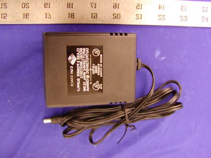
Click to zoom
Application Details
- Equipment Class
- NII - Unlicensed National Information Infrastructure TX
- Date of Grant
- Feb 27, 2003
- Application Purpose
- Original Equipment
- Date of Application
- Feb 27, 2003
- Equipment Note
- 5 GHz Wireless Access Point
- Frequency Range
- 5260.00000000 - 5340.00000000
- Company
- Trango Systems Inc
- Country
- United States
Documents & Files
Document Text
Text extracted from the exhibit documents filed with the FCC. Open a document above to read the original.
Users Manual
A Access5830 Series User Manual-Draft January 2003 •Trango Broadband Wireless •15070 Ave. of Science, Ste. 200 •San Diego, California 92128 •T 858-653-3900 •F 858-621-2725 Trango Broadband Wireless Access5830™ User Manual User Manual Rev 1 2 Copyright 2001-2003 Trango Broadband Wireless, A division of Trango Systems, Inc. No part of this publication may be reproduced in any form without the written permission of the copyright owner. The information in this publication is subject to change without notice. Trango Broadband Wireless shall not be liable for errors contained herein or for incidental or consequential damages in connection with the furnishing, performance, or use of this manual or the equipment it refers to. FCC Information: This device complies with Part 15 of the FCC Rules. Operation is subject to the following two conditions: (1) This device may not cause harmful interference, and (2) this device must accept any interference received, including interference that may cause undesired operation. This equipment has been tested and found to comply with the limits for a Class B digital device, pursuant to Part 15 of the FCC Rules. These limits are designed to provide reasonable protection against harmful interference in a residential installation. This equipment generates, uses, and can radiate radio frequency energy, and if not installed and used in accordance with these instructions, may cause harmful interference to radio communications. However, there is no guarantee that interference will not occur in a particular installation. If this equipment does cause harmful interference to radio or television reception, which can be determined by turning the equipment off and on, the user is encouraged to correct the interference by one of more of the following measures: 1) Reorient the antenna; 2) Increase the separation between the affected equipment and the unit; 3) Connect the affected equipment to an outlet on a different circuit from that which the receiver is connected to; 4) Consult the dealer and/or experienced radio/TV technician for help. FCC ID Numbers: FCC ID: NCYM5830SAP60 FCC ID: NCYM5830SSU FCC ID: NCYM5830SSUEXT CANADA: TBD IMPORTANT NOTE: Intentional or unintentional changes or modifications not expressly approved by the party responsible for compliance must not be made. Any such modifications could void the user’s authority to operate the equipment and will void the manufacturer’s warranty. To maintain compliance with the FCC's RF exposure guidelines, both units must be operated at least 20 cm from any person. This is necessary to insure that the product is operated in accordance with the RF Guidelines for Human Exposure which have been adopted by the Federal Communication Commission. Trango Broadband Wireless Access5830™ User Manual User Manual Rev 1 3 CONTENTS 1. For your safety.....................................................................4 2. Welcome............................................................................4 2.1. Documentation conventions....................................................4 2.2. Check List..........................................................................5 2.3. Service..............................................................................6 3. Components and Features.......................................................6 3.1. System Overview..................................................................6 3.2. Access Point Unit.................................................................6 3.3. Junction Box.......................................................................7 3.4. Subscriber Unit....................................................................7 4. Installation.........................................................................8 4.1. Access Point Mechanical Installation..........................................8 4.2. Subscriber Unit Mechanical Installation......................................8 4.3. Wiring.............................................................................10 4.4. Antenna Alignment.............................................................10 4.5. Grounding........................................................................11 5. Setup..............................................................................12 5.1. Step by Step Configuration of The AP....................................12 5.2. Step by Step Configuration of The SU....................................23 6. Site Planning.....................................................................28 7. Administration Tools............................................................37 7.1. Network Security...............................................................37 7.2. Subscriber Database Management...........................................37 8. Troubleshooting.................................................................38 9. Theory of Operation............................................................42 9.1. Hardware.........................................................................42 9.1.1. 5.8 GHz Direct Sequence Spread Spectrum.............................42 9.1.2. Antenna Technology.........................................................42 9.2. Software..........................................................................42 10. Specifications.................................................................44 10.1. M5800S-AP-60 Specifications...............................................44 10.2. M5800S-SU Series Specifications..........................................48 APPENDIX: FIRMWARE – HARDWARE CROSS REFERENCE.............................52 Trango Broadband Wireless Access5830™ User Manual User Manual Rev 1 4 1. For your safety WARNING Use extreme care when installing antennas near power lines. Antenna Installation Instructions: FCC RF Exposure Limits CAUTION Do not apply power to the transmitter until the antenna is connected. Permanent damage may result. CAU…
Text truncated - open the document above for the full version.
Cover Letter(s)
15070 Avenue of Science, Suite 200 San Diego, CA 92128 Ph: 858-653-3900 Fax: 858-621-2725 Federal Communications Commission Authorization and Evaluation Division Confidentiality Request regarding application for certification of FCC ID: NCYM5830SAP60 Pursuant to Sections 0.457 and 0.459 of the Commission’s Rules, we hereby request confidential treatment of information accompanying this application as outlined below: Schematic Block Diagram The above materials contain trade secrets and proprietary information not customarily released to the public. The public disclosure of these materials may be harmful to the applicant and provide unjustified benefits to its competitors. The applicant understands that pursuant to Section 0.457 of the Rules, disclosure of this application and all accompanying documentation will not be made before the date of the Grant for this application. Sincerely, Christopher A. Gustaf
External Photos
EXHIBIT C - EUT EXTERNAL PHOTOGRAPHS EUT - Front View EUT - Rear View AC/ DC Adapter Top View Adapter Top View Adapter Port1 Adapter Port2
ID Label/Location Info
EXHIBIT A - FCC ID LABEL INFORMATION Proposed FCC ID Label Proposed Label Location on EUT Rear View of EUT/FCC ID Label FCC ID:NCYM5830SAP60 This device complies with Part 15 o the FCC Rules. Operation is subject to the following two conditions: (1) this device may not cause harmful interference, and (2) this device must accept any interference received, including interference that may cause undesired operation. 2.1875" 1.0"
Internal Photos
EXHIBIT C - EUT INTERNAL PHOTOGRAPHS EUT – Component View EUT – Component View with Sub Shield EUT - Solder View EUT – Port View EUT – Housing and Board EUT - Antenna Component View EUT – Antenna Solder View Adapter Component View Adapter Solder View
Operational Description
Product Specification: 710-9759 Rev 1 5.3/5.8 GHz Dual Band Spread Spectrum Broadband Wireless Internet Access Access Point Unit with Integral Patch Models: M5830S-AP-60 November 27, 2002 ENGINEERING: MARKETING: DATE: DATE: 1.0 SUMMARY This document details the functional and parametric requirements for the access point (AP), which, when setup in a cell having at least one subscriber unit (SU) transceiver functions as a wireless MAC layer Ethernet access solution. Each AP communicates with each SU using 5.3 and 5.8 GHz spread spectrum technology. The AP accepts full or half duplex Ethernet IEEE 802.3 data packets from a 10/100BaseT port, encodes them, and transmits them at 11 Mbit/sec rate over the air. Figure 1 shows the block diagram of the unit and the major signals used. The Access Point product consists of the following: - 1 Access point unit (AP) with integrated patch antenna - 1 Pole/wall mount kit - 1 Junction Box for power injection - 1 Power adapter - 1 Programming cable 2.0 FUNCTIONAL REQUIREMENTS The paragraphs below describe the functional requirements of the transceiver. 2.1.1 GENERAL REQUIREMENTS The unit shall be designed to be compliant with FCC part 15.247/15.407 intentional radiator requirements for a point to multipoint system, and 15.109 unintentional radiator requirements. This requirement specifies certain maximum RF power output and spurious emissions levels. This device will automatically discontinue transmission in case of either absence of information to transmit or operational failure. These provisions are not intended to preclude the transmission of control or signaling information or the use of repetitive codes used by certain digital technologies to complete frame or burst intervals. The unit shall be designed for installation by a professional installer or the end customer. 2.1.2 HARDWARE REQUIREMENTS 2.1.2.1 User Controls and Indicators 2.1.2.1.1 LEDs LED operational requirements are given below. It should be noted, however, that in “Survey” mode, no LEDs shall light up except the LNKST and ACTST LEDs. The unit shall have LED indicators to indicate the following: a) LNKST LED Green: Flashes with Ethernet port activity (LNKST) b) ACTST LED Green: Receive/Transmit Status (ACTST) c) RSSI LED In all modes except “Survey”, the unit shall have one yellow LED that indicates the level of RF signal being received and blinks faster with increasing signal strength and slower with less signal strength. If no signal is detected the LED will not blink at all. The level of the signal must be above –80 dBm to start the blinking. At –65 dBm the LED shall go solid. The LED shall be controlled by the FPGA and is based upon the Prism RSSI register, which indicate the energy level on the antenna. d) Transmit LED In all modes except “Survey”, this red LED shall light up for 300 milliseconds whenever the unit transmits a packet over the RF link and the CPU receives end of transmit confirmation from the FPGA. It shall be set by the CPU and routed through the FPGA. e) Receive LED In OFF mode, this green LED shall blink for 300 milliseconds whenever the unit receives a good (checksum passed) data packet across the RF link from a valid SU. It shall be set by the CPU and routed through the FPGA. In “AP SEARCH” mode, the LED shall blink when the AP receives a payload packet addressed to any SU. 2.1.2.1.2 Connectors The unit shall have a connector for a 10/100 Base T shielded twisted pair (STP) interface cable connection. The unit shall have a right angle connector for a serial terminal (Console) connection. The unit shall be powered using the unused twisted pair wires. . 2.1.2.2 Power Input The unit shall have provisions to operate from an unregulated DC power supply. This input shall be reverse voltage polarity protected and have filtering to prevent damage from static caused by typical nearby lightning strikes and the human body ESD model. The unit shall have automatically resetting fusing provisions in the event of an over current condition. 2.1.2.3 Digital Section Figure 2 shows the digital subsystem block diagram. 2.1.2.3.1 Microprocessor Subsystem The unit shall utilize a 32 bit RISC microprocessor to accomplish the requirements in the software section. The subsystem shall consist of the following hardware functions: 1) 32 Bit Microprocessor with SDRAM controller 2) Ethernet PHY interface 3) RS232 Serial port for administration 4) Nonvolatile, writeable FLASH Memory 1Mbytes 5) SDRAM 8 Mbytes 2.1.2.3.2 Field Programmable Gate Array (FPGA) A field programmable gate array shall be used to accomplish the following functions: 1) 32 bit wide, 256 long word deep, full duplex FIFO for RF MAC packet transfer to and from the microprocessor subsystem to the radio section Baseband Processor (BBP) 2) Microprocessor subsystem data bus interface for transferring data between the microprocessor and the FPGA 3) Shift register for to convert RF MAC packets going between the FIFO and the BBP from parallel to serial format. 4) PLL programming for IF and RF local oscillators. 5) TX/RX switch processing. 6) BBP register read/write 7) JTAG interfacing to test equipment 8) Ranging response processing 9) Polling response processing 10) Timer to support CPU 11) RSSI LED support 12) Antenna switch control (polarization) 13) Band Switching Control 2.1.2.3.3 Baseband Processor (BBP), Modulator and Demodulator The unit shall use the Intersil Prism II chipset solution for modulating and demodulating RF MAC layer packets onto the RF channel. The portion of the chipset that shall be used consists of the BBP and the Quadrature Modulator/Demodulator. Functions of the solution that shall be utilized: 1) Data Transmit 2) Data Receive 3) Data scrambling. 4) IF AGC 5) Received Signal Strength monitoring 6) Clear Channel Assessment. 7) RF power output adjustment 2.1.2.4 RF/Analog Section The unit RF section shall be designed as a half duplex transceiver. The unit shall use a single-conversion receiver architecture. T…
Text truncated - open the document above for the full version.
RF Exposure Info
RF EXPOSURE According to §1.1307(b)(1), systems operating under the provisions of this section shall be operated in a manner that ensures that the public is not exposed to radio frequency energy level in excess of the Commission’s guidelines. According to §1.1310 and §2.1093 RF exposure is calculated. Limits for Maximum Permissive Exposure (MPE) (A) Limits for General Population/Uncontrolled Exposure Frequency Range (MHz) Electric Field Strength (V/m) Magnetic Field Strength (A/m) Power Density (mW/cm 2 ) Averaging Time (minute) Limits for General Population/Uncontrolled Exposure 0.3-1.346141.63*(100)30 1.34-30824/f2.19/f*(180/f 2 )30 30-30027.50.0730.230 300-1500//f/150030 1500-100,000//1.030 (B) Limits for Occupational/Controlled Exposures Frequency Range (MHz) Electric Field Strength (V/m) Magnetic Field Strength (A/m) Power Density (mW/cm 2 ) Averaging Time (minute) Limits for Occupational/Controlled Exposure 0.3-3.06141.63*(100)6 3.0-301842/f4.89/f*(900/f 2 )6 30-30061.40.1631.06 300-1500//f/3006 1500-100,000//56 f = frequency in MHz * = Plane-wave equivalent power density MPE Prediction Predication of MPE limit at a given distance Equation from page 18 of OET Bulletin 65, Edition 97-01 S = PG/4πR² Where: S = power density P = power input to antenna G = power gain of the antenna in the direction of interest relative to an isotropic radiator R = distance to the center of radiation of the antenna Test Result Maximum Peak Output (dBm) Antenna Gain (dBi) Uncontrolled Exposure MPE Minimum Distance (cm) 20.70 (High Band, 5736~5836MHz) 1415.3 cm 16.43 (Low Band, 5260~5340MHz) 138.4 cm Note: The EUT is defined to be a mobile device. The user manual states that the minimum distance is 20 cm in order to accommodate all various antenna gains available for this device.
Test Report
Note: This test report is specially limited to the above client company and product model only. It may not be duplicated without prior written consent of Bay Area Compliance Laboratory Corporation. This report must not be used by the client to claim product endorsement by NVLAP or any agency of the U.S. Government. FCC PART 15 TEST REPORT For Trango Systems, Inc. 15070 Avenue of Science, Suite 200 San Diego, CA 92128 FCC ID: NCYM5830SAP60 January 13, 2003 This Report Concerns: Original Report Equipment Type: 5GHz Wireless Access Point Test Engineer: Jeff Lee Report No.: R0211221 Test Date: December 18, 2002 Reviewed By: Hans Mellberg Prepared By: Bay Area Compliance Laboratory Corporation (BACL) 230 Commercial Street Sunnyvale, CA 94085 Tel: (408) 732-9162 Fax: (408) 732 9164 Trango Systems, Inc. FCC ID: NCYM5830SAP60 Report # R0211221Rpt.doc Page 2 of 58 FCC Part 15.247 & 15.407 Test Report TABLE OF CONTENTS 1 - GENERAL INFORMATION.................................................................................................................................................4 1.1 PRODUCT DESCRIPTION FOR EQUIPMENT UNDER TEST (EUT)........................................................................................4 1.2 OBJECTIVE................................................................................................................................................................................4 1.3 RELATED SUBMITTAL(S)/GRANT(S).....................................................................................................................................4 1.4 TEST METHODOLOGY..............................................................................................................................................................4 1.5 TEST FACILITY.........................................................................................................................................................................4 1.6 TEST EQUIPMENT LIST............................................................................................................................................................5 1.7 HOST SYSTEM CONFIGURATION LIST AND DETAILS..........................................................................................................5 1.8 LOCAL SUPPORT EQUIPMENT LIST AND DETAILS...............................................................................................................5 1.9 EXTERNAL I/O CABLING LIST AND DETAILS......................................................................................................................6 2 - SYSTEM TEST CONFIGURATION..................................................................................................................................7 2.1 JUSTIFICATION..........................................................................................................................................................................7 2.2 EUT EXERCISE SOFTWARE....................................................................................................................................................7 2.3 SPECIAL ACCESSORIES............................................................................................................................................................7 2.4 SCHEMATICS / BLOCK DIAGRAM...........................................................................................................................................7 2.5 EQUIPMENT MODIFICATIONS.................................................................................................................................................7 2.6 CONFIGURATION OF TEST SYSTEM.......................................................................................................................................8 2.7 TEST SETUP BLOCK DIAGRAM...............................................................................................................................................8 3 - SUMMARY OF TEST RESULTS........................................................................................................................................9 4 - PEAK OUTPUT POWER MEASUREMENT................................................................................................................10 4.1 STANDARD APPLICABLE.......................................................................................................................................................10 4.2 MEASUREMENT PROCEDURE................................................................................................................................................10 4.3 MEASUREMENT RESULT.......................................................................................................................................................10 5 – 6 DB BANDWIDTH AND 26 DB BANDWIDTH..........................................................................................................14 5.1 STANDARD APPLICABLE.......................................................................................................................................................14 5.2 MEASUREMENT PROCEDURE................................................................................................................................................14 5.3 MEASUREMENT RESULT.......................................................................................................................................................14 6 - POWER SPECTRAL DENSITY........................................................................................................................................18 6.1 STANDARD APPLICABLE.......................................................................................................................................................18 6.2 MEASUREMENT PROCEDURE.................................................................................................................…
Text truncated - open the document above for the full version.
Test Setup Photos
EXHIBIT B - TEST SETUP PHOTOGRAPHS Conducted Emission - Front View Conducted Emission - Rear View Radiated Emission - Front View Radiated Emission - Rear View
Contact Information
Applicant
Christopher A Gustaf(VP, Engineering)
Test Firm
Bay Area Compliance LaboratoryJohn Chan
Technical Specifications
| # | Rule Parts | Frequency Range | Power Output |
|---|---|---|---|
| 1 | 15E | 5.26 GHz - 5.34 GHz | 43.90 mW |
Other Applications from Trango Systems Inc
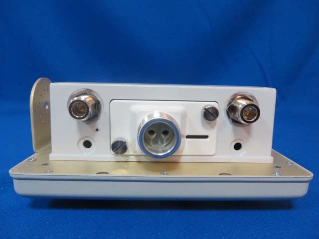
NCY-A600
Jan 28, 2015Altum AC600
Equipment Class
JBP - Part 15 Class B Computing Device Peripheral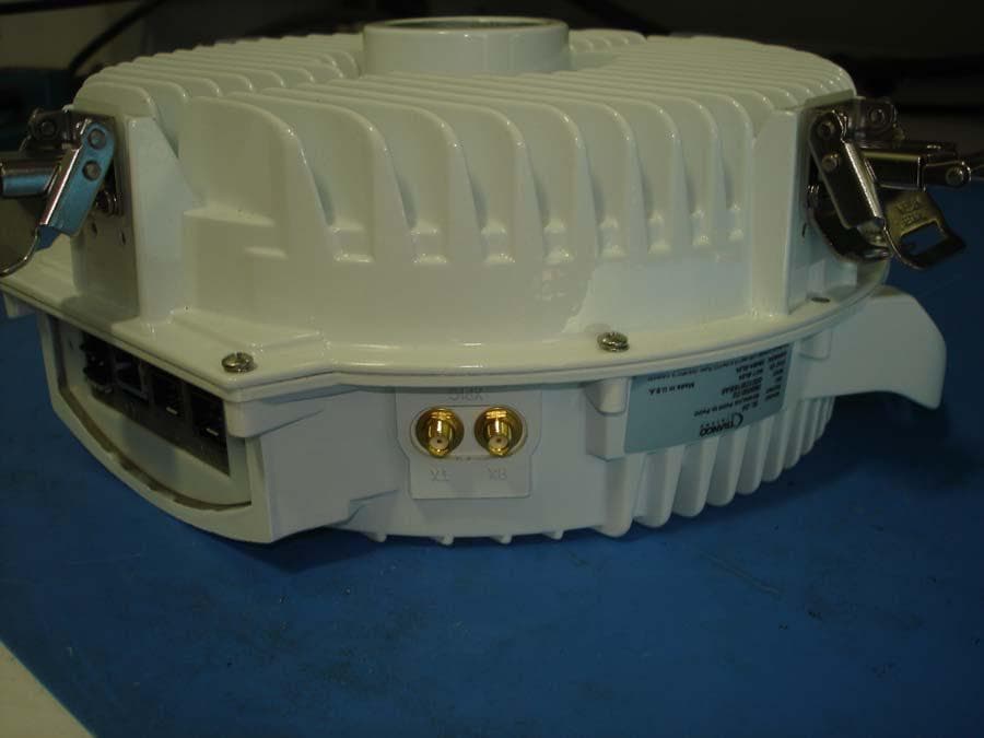
NCY-SL24
Feb 05, 201324 GHz Wireless Point to Point Data Transmission System
Equipment Class
DXX - Part 15 Low Power Communication Device Transmitter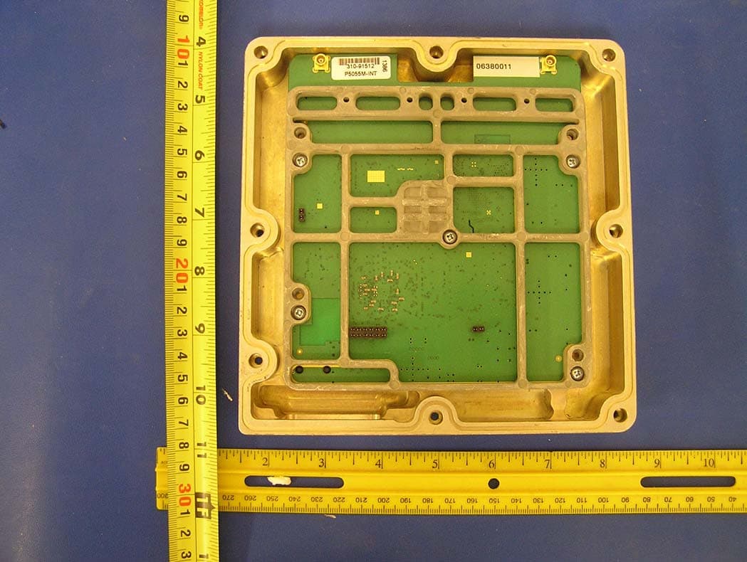
NCYP5055M
Sep 25, 2007802.11 a Point to Point Transceiver
Equipment Class
DTS - Digital Transmission System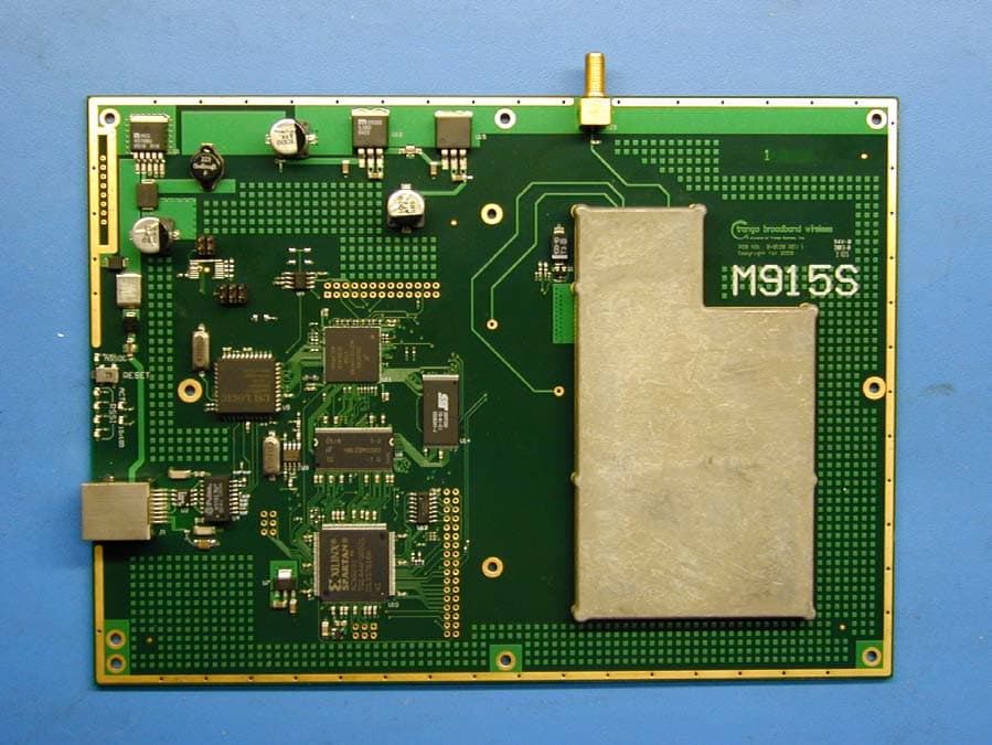
NCYM915S
Jan 16, 2006900 MHz Transceiver
Equipment Class
DTS - Digital Transmission System
NCYM5580MFSU
Jan 02, 2006Wireless Internet Access Subscriber Unit
Equipment Class
DTS - Digital Transmission System