NDX-GATEMAXRFID Reader
Datamars SA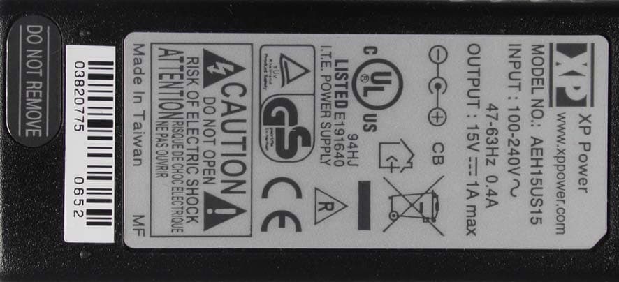
Click to zoom
Application Details
- Equipment Class
- DCD - Part 15 Low Power Transmitter Below 1705 kHz
- Date of Grant
- Nov 06, 2007
- Application Purpose
- Original Equipment
- Date of Application
- Nov 06, 2007
- Equipment Note
- RFID Reader
- Frequency Range
- 0.13400000 - 0.13400000
- Company
- Datamars SA
- Country
- Switzerland
Documents & Files
Document Text
Text extracted from the exhibit documents filed with the FCC. Open a document above to read the original.
Users Manual
User Manual GATE MAX READER This manual describes the use of the GATE MAX reader. The GATE MAX reader is a high-performance Radio Frequency Transponder reader. The GATE MAX reads all ISO 11784/85 FDX/B Transponders for the electronic identification of animals. It helps to reunite the animal with its owner. The GATE MAX reader and the Transponders are manufactured according to ISO Standards 11784 & 11785 for the electronic identification of animals and are products. Index 0. Important 1. Introduction 2. GATE MAX Reader System 3. Main Advantages 4. How to Connect 5. Operation (for readers with display) 6. How to Use the GATE MAX Reader 7. Settings and User Interface 7.1.Main Screen 7.1.1. Reading OFF 7.1.2. Reading ON 7.2.Option Menu 7.3.Noise Level 8. Reader Connected to a PC or a Data Recording System 8.1.PC Commands 9. Cleaning 10. Regulations 1. Introduction The GATE MAX reader has been especially designed for shelters, veterinary clinics and borders to facilitate the pet identification process. The GATE MAX system is composed of a reader, a gate antenna and a power supply. The GATE MAX reader allows a hands free direct identification of the pet when passing through the antennas. The pet simply goes through the reader, the ID number gets read automatically and displayed either on the touch screen (optionally provided)mounted on the antenna or on the computer screen of the clinic,shelter or border. No manual tipping is necessary, which avoids human error in typing the 15 digits ID number and eases the process. 2. GATE MAX Reader System The GATE MAX reader system is in accordance with ISO Standard 11785 and reads the ISO tags FDX-B. The reading range covers the area between the antennas completely. The reader can be connected to a PC: the ID will be displayed either on the touch screen mounted on the antenna (optionally provided) or on the PC screen. The reader includes a RS232 interface for data transmission (ASCII) and can include, alternatively, a USB interface. This system can easily be integrated into an Open Office Package for a database which is used in shelters or veterinary clinics. 4. How to Connect Before start: Plug in the RS232 cable from the GATE MAX reader unit connector to the serial communication COM port of your PC. Optionally, you can plug in a USB cable and install its software on your PC. Then plug in the power cable. The reader is automatically powered by using the ON/OFF switch. 5. Operation (for readers with display) To start reading push the ‘Start’ button on the touch screen (optionally pro- vided). The reader turns on the transmission and now is ready to detect transpon- ders. The display shows the status of the reader with a blinking text ‘Reading’ and with a blinking button. When a transponder is detected, the ID number is shown on the screen. It remains displayed until a new transponder is detected or ”Clear ID” is pressed. To stop the transmission press ‘Stop’. The display shows the status writing ‘Stand-by’. 3. Main Advantages The GATE MAX reader is designed to facilitate pet identification. The main benefits are automatic recognition of the transponder FDX-B (ISO Standard), quick detection (normally no need to scan the pet manually), a safer use for the employees and an automatic process (connection to a database and PC). RS-232 Cable USB Cable Power Cable 3 0. Important This product is sensitive to any external radio frequency disturbances due to the large size of the antennas. Therefore, be aware of its surrounding environment. The following objects can cause interference with the GATE MAX reader and for this reason it is recommended to maintain a distance of 2 to 3 meters: ■Large PC/ TV screen (not flat screens) ■Lamps, motors ■Metal objects (scales, tables, gates, cages, etc.) ■Other RFID handheld readers (e.g. ISO MAX IV) 6. How to Use the GATE MAX Reader ■When a pet passes through the antennas, the transponder is automati- cally detected. If not, make the dog walk slowly 2-3 times through the antennas. A short stand still of 2 seconds between the antennas may also help. ■If a transponder is detected between the antennas, the code is auto- matically read and sent through the RS232 communication cable once. At the same time an ID number is written on the screen. ■If no transponder is present, the read cycle continues. The system reads 30 times per second. ■The GATE MAX reader system detects around 80% of the ISO transponders during the first passage. ■If the pet’s transponder is still not detected after the 3 rd passage, we recommend using a hand-held multi reader with a large antenna (example ISO MAX IV) in order to determine or exclude the presence of an animal identification transponder. Walk through OK NO 3 rd time Verify with handheld reader Display number? if no number please try again 981094573680810 NO 1.Let the pet walk through the reader. The transponder is automatically detected. 2.If no number is displayed, please try again. The reader did not detect a transponder this time. 3.If no number is displayed after three times, please verify that a transponder exists with a portable reader. GATE MAX Reader 4 8. Reader Connected to a PC or a Data Recording System The system has a RS232 interface which communicates with the PC via a serial port (COM) sending all data in ASCII. HyperTerminal can be used as a communication program. Start > Programs > Accessories > Communications > Hyper Terminal Set the communication parameters as follows: Where ‘Name’ is a customer choice. 7. Settings and User Interface 7.1Main Screen 7.1.1 Reading OFF Start Button: Turns on the transmission and reads continuously. Option Button: Go to the ‘option’ menu. 7.1.2 Reading ON Stop Button: Turns off the transmission and stops the reader. Clear ID Button: Clears the ID on the display screen to allow an easier visualization of the next ID. When Single Mode is selected, it reads another time the same ID. The ID is shown below the ‘ID:’ text. It is composed of 15 numbers. The…
Text truncated - open the document above for the full version.
Cover Letter(s)
Date: 29.10.2007 Federal Communications Commission 7435 Oakland Mills Road Columbia, MD 21046 Re: Request of Confidentiality Pursuant to Sections 0.457(d)(1)(ii) and 0.459 of the Commission’s Rules, the Applicant hereby requests confidential treatment of information accompanying as outlined below for the following FCC ID: NDX-GATE MAX Schematics, Operating Description, Block Diagram, Parts List The above materials contain trade secrets and proprietary information not customarily released to the public. The public disclosure of these matters might be harmful to the Applicant and provide unjustified benefits to its competitors. The Applicant understands that pursuant to Rule 0.457(d)(1)(ii), disclosure of this Application and all accompanying documentation will not be made before the date of the Grant for this Application. Sincerely, Thomas Ring Manager: Certification mikes-testingpartners gmbh ohmstrasse 2-4 94342 Strasskichen, Germany Phone: 0049 9424 9481 0 Fax: 0049 9424 9481 240
External Photos
FCC ID:NDX-GATEMAX mikes-testingpartners gmbh File No. T31765-02-00HU, page 5 of 30 Ohmstrasse 2-4 x 94342 Strasskirchen Tel.:+49(0)9424-94810 x Fax:+49(0)9424-9481240 Rev. No. 1.1 3 EQUIPMENT UNDER TEST 3.1 Photo documentation of the EuT FCC ID:NDX-GATEMAX mikes-testingpartners gmbh File No. T31765-02-00HU, page 9 of 30 Ohmstrasse 2-4 x 94342 Strasskirchen Tel.:+49(0)9424-94810 x Fax:+49(0)9424-9481240 Rev. No. 1.1 Electronic chassis side view: FCC ID:NDX-GATEMAX mikes-testingpartners gmbh File No. T31765-02-00HU, page 10 of 30 Ohmstrasse 2-4 x 94342 Strasskirchen Tel.:+49(0)9424-94810 x Fax:+49(0)9424-9481240 Rev. No. 1.1 Power Supply: FCC ID:NDX-GATEMAX mikes-testingpartners gmbh File No. T31765-02-00HU, page 11 of 30 Ohmstrasse 2-4 x 94342 Strasskirchen Tel.:+49(0)9424-94810 x Fax:+49(0)9424-9481240 Rev. No. 1.1 Touch Panel:
ID Label/Location Info
FCC ID:NDX-GATEMAX mikes-testingpartners gmbh File No. T31765-02-00HU, page 5 of 30 Ohmstrasse 2-4 x 94342 Strasskirchen Tel.:+49(0)9424-94810 x Fax:+49(0)9424-9481240 Rev. No. 1.1 3 EQUIPMENT UNDER TEST 3.1 Photo documentation of the EuT
Internal Photos
FCC ID:NDX-GATEMAX mikes-testingpartners gmbh File No. T31765-02-00HU, page 6 of 30 Ohmstrasse 2-4 x 94342 Strasskirchen Tel.:+49(0)9424-94810 x Fax:+49(0)9424-9481240 Rev. No. 1.1 Antenna matching board: FCC ID:NDX-GATEMAX mikes-testingpartners gmbh File No. T31765-02-00HU, page 7 of 30 Ohmstrasse 2-4 x 94342 Strasskirchen Tel.:+49(0)9424-94810 x Fax:+49(0)9424-9481240 Rev. No. 1.1 Electronic open chassis: FCC ID:NDX-GATEMAX mikes-testingpartners gmbh File No. T31765-02-00HU, page 8 of 30 Ohmstrasse 2-4 x 94342 Strasskirchen Tel.:+49(0)9424-94810 x Fax:+49(0)9424-9481240 Rev. No. 1.1 FCC ID:NDX-GATEMAX mikes-testingpartners gmbh File No. T31765-02-00HU, page 12 of 30 Ohmstrasse 2-4 x 94342 Strasskirchen Tel.:+49(0)9424-94810 x Fax:+49(0)9424-9481240 Rev. No. 1.1 FCC ID:NDX-GATEMAX mikes-testingpartners gmbh File No. T31765-02-00HU, page 13 of 30 Ohmstrasse 2-4 x 94342 Strasskirchen Tel.:+49(0)9424-94810 x Fax:+49(0)9424-9481240 Rev. No. 1.1
Test Report
FCC ID:NDX-GATEMAX mikes-testingpartners gmbh File No. T31765-02-05HU, page 1 of 30 Ohmstrasse 2-4 x 94342 Strasskirchen Tel.:+49(0)9424-94810 x Fax:+49(0)9424-9481240 Rev. No. 1.1 EMI -- T E S T R E P O R T Test Report No. : T31765-02-05HU 31. October 2007 ______________________________________________________________________________________________ Date of issue Type / Model Name : Gate Max Product Description : Gate antenna for a low frequency long range reader Applicant : Datamars SA Address : Via ai Prati CH – 6930 Bedano Manufacturer : Datamars SA Address : Via ai Prati CH – 6930 Bedano Licence holder : Datamars SA Address : Via ai Prati CH – 6930 Bedano Test Result according to the standards listed in clause 1 test standards: POSITIVE The test report merely corresponds to the test sample. It is not permitted to copy extracts of these test results without the written permission of the test DAT-P-207/05-00 laboratory. FCC ID:NDX-GATEMAX mikes-testingpartners gmbh File No. T31765-02-05HU, page 2 of 30 Ohmstrasse 2-4 x 94342 Strasskirchen Tel.:+49(0)9424-94810 x Fax:+49(0)9424-9481240 Rev. No. 1.1 Contents 1 TEST STANDARDS 3 2 SUMMARY 4 3 EQUIPMENT UNDER TEST 5 3.1 PHOTO DOCUMENTATION OF THE EUT 5 3.2 POWER SUPPLY SYSTEM UTILISED 14 3.3 SHORT DESCRIPTION OF THE EQUIPMENT UNDER TEST (EUT) 14 4 TEST ENVIRONMENT 15 4.1 ADDRESS OF THE TEST LABORATORY 15 4.2 ENVIRONMENTAL CONDITIONS 15 4.3 STATEMENT OF THE MEASUREMENT UNCERTAINTY 15 4.4 MEASUREMENT PROTOCOL FOR FCC, VCCI AND AUSTEL 15 5 TEST CONDITIONS AND RESULTS 17 5.1 CONDUCTED EMISSIONS 17 5.2 FIELD STRENGTH OF THE FUNDAMENTAL WAVE 21 5.3 SPURIOUS EMISSIONS (MAGNECTIC FIELD) 9 KHZ – 30 MHZ 23 5.4 RADIATED EMISSIONS (ELECTRIC FIELD) 30 MHZ – 1 GHZ 25 5.5 EMISSION BANDWIDTH 27 6 USED TEST EQUIPMENT AND ACCESSORIES 29 FCC ID:NDX-GATEMAX mikes-testingpartners gmbh File No. T31765-02-05HU, page 3 of 30 Ohmstrasse 2-4 x 94342 Strasskirchen Tel.:+49(0)9424-94810 x Fax:+49(0)9424-9481240 Rev. No. 1.1 1 TEST STANDARDS The tests were performed according to following standards: FCC Rules and Regulations Part 15 Subpart C- Intentional Radiators (May, 2007) Part 15, Subpart C, Section 15.209(a) Radiated emissions, general requirements Part 15, Subpart C, Section 15.207(a) AC Line conducted emissions FCC ID:NDX-GATEMAX mikes-testingpartners gmbh File No. T31765-02-05HU, page 4 of 30 Ohmstrasse 2-4 x 94342 Strasskirchen Tel.:+49(0)9424-94810 x Fax:+49(0)9424-9481240 Rev. No. 1.1 2 SUMMARY GENERAL REMARKS: FINAL ASSESSMENT: The equipment under test fulfills the EMI requirements cited in clause 1 test standards. Date of receipt of test sample : acc. to storage records Testing commenced on : 30. Mai 2007 Testing concluded on : 10. September 2007 Checked by: Tested by: Thomas Weise Dipl.-Ing.(FH) Laboratory Manager Huber Markus FCC ID:NDX-GATEMAX mikes-testingpartners gmbh File No. T31765-02-05HU, page 5 of 30 Ohmstrasse 2-4 x 94342 Strasskirchen Tel.:+49(0)9424-94810 x Fax:+49(0)9424-9481240 Rev. No. 1.1 3 EQUIPMENT UNDER TEST 3.1 Photo documentation of the EuT FCC ID:NDX-GATEMAX mikes-testingpartners gmbh File No. T31765-02-05HU, page 6 of 30 Ohmstrasse 2-4 x 94342 Strasskirchen Tel.:+49(0)9424-94810 x Fax:+49(0)9424-9481240 Rev. No. 1.1 Antenna matching board: FCC ID:NDX-GATEMAX mikes-testingpartners gmbh File No. T31765-02-05HU, page 7 of 30 Ohmstrasse 2-4 x 94342 Strasskirchen Tel.:+49(0)9424-94810 x Fax:+49(0)9424-9481240 Rev. No. 1.1 Electronic open chassis: FCC ID:NDX-GATEMAX mikes-testingpartners gmbh File No. T31765-02-05HU, page 8 of 30 Ohmstrasse 2-4 x 94342 Strasskirchen Tel.:+49(0)9424-94810 x Fax:+49(0)9424-9481240 Rev. No. 1.1 FCC ID:NDX-GATEMAX mikes-testingpartners gmbh File No. T31765-02-05HU, page 9 of 30 Ohmstrasse 2-4 x 94342 Strasskirchen Tel.:+49(0)9424-94810 x Fax:+49(0)9424-9481240 Rev. No. 1.1 Electronic chassis side view: FCC ID:NDX-GATEMAX mikes-testingpartners gmbh File No. T31765-02-05HU, page 10 of 30 Ohmstrasse 2-4 x 94342 Strasskirchen Tel.:+49(0)9424-94810 x Fax:+49(0)9424-9481240 Rev. No. 1.1 Power Supply: FCC ID:NDX-GATEMAX mikes-testingpartners gmbh File No. T31765-02-05HU, page 11 of 30 Ohmstrasse 2-4 x 94342 Strasskirchen Tel.:+49(0)9424-94810 x Fax:+49(0)9424-9481240 Rev. No. 1.1 Touch Panel: FCC ID:NDX-GATEMAX mikes-testingpartners gmbh File No. T31765-02-05HU, page 12 of 30 Ohmstrasse 2-4 x 94342 Strasskirchen Tel.:+49(0)9424-94810 x Fax:+49(0)9424-9481240 Rev. No. 1.1 FCC ID:NDX-GATEMAX mikes-testingpartners gmbh File No. T31765-02-05HU, page 13 of 30 Ohmstrasse 2-4 x 94342 Strasskirchen Tel.:+49(0)9424-94810 x Fax:+49(0)9424-9481240 Rev. No. 1.1 FCC ID:NDX-GATEMAX mikes-testingpartners gmbh File No. T31765-02-05HU, page 14 of 30 Ohmstrasse 2-4 x 94342 Strasskirchen Tel.:+49(0)9424-94810 x Fax:+49(0)9424-9481240 Rev. No. 1.1 3.2 Power supply system utilised Power supply voltage : 115 V / 60 Hz / 1φ 15 V / DC 3.3 Short description of the Equipment under Test (EuT) The EuT Gate Max is a low frequency long range reader gate antenna system for animal identification. Number of tested samples: 1 Serial number: see Photo documentation of the EuT under Point 3 / Equipment Under Test EuT operation mode: The equipment under test was operated during the measurement under the following conditions: - Continuous sweep mode at 134.2 kHz - - EuT configuration: (The CDF filled by the applicant can be viewed at the test laboratory.) The following peripheral devices and interface cables were connected during the measurements: - Power supply type B Model : AEH15US15, S/N: 03820775/0652 - AC power line, shielded and filtered Model : Eupen IMU 03 - Model : - Model : - Model : - Model : - customer specific cables FCC ID:NDX-GATEMAX mikes-testingpartners gmbh File No. T31765-02-05HU, page 15 of 30 Ohmstrasse 2-4 x 94342 Strasskirchen Tel.:+49(0)9424-94810 x Fax:+49(0)9424-9481240 Rev. No. 1.1 4 TEST ENVIRONMENT 4.1 Address of the test laboratory mikes-testingpartners gmbh Ohmstrasse 2-4 94342 Strasskirchen Germany 4.2 Environmental co…
Text truncated - open the document above for the full version.
Test Setup Photos
FCC ID:NDX-GATEMAX mikes-testingpartners gmbh File No. T31765-02-00HU, page 21 of 30 Ohmstrasse 2-4 x 94342 Strasskirchen Tel.:+49(0)9424-94810 x Fax:+49(0)9424-9481240 Rev. No. 1.1 5.2 Field strength of the fundamental wave For test instruments and accessories used see section 6 Part CPR 1. 5.2.1 Description of the test location Test location: OATS1 Test distance: 3 metres 5.2.2 Photo documentation of the test set-up 5.2.3 Description of Measurement The magnetic field strength from the EuT will be measured on an open area test site in the frequency range of 9 kHz to 30 MHz using a tuned receiver and a shielded loop antenna. The set up of the Equipment under test will be in accordance to ANSI C63.4-2003. The antenna was positioned 3, 10 or 30 meters horizontally from the EuT. Measurements have been made in all three orthogonal axes and the shielded loop antenna was rotated to locate the maximum of the emissions. In the case where larger measuring distances are required the results will extrapolated based on the values measured on the closer distances according to Section 15.31 (f) (2) [2]. The final measurement will be performed with an EMI Receiver set to Quasi Peak detector except for the frequency bands 9 kHz to 90 kHz and 110 to 490 kHz where an average detector will be used according to Section 15.209 (d) [2]. The final level, expressed in dBμV/m, is arrived at by taking the reading from the EMI receiver (Level dBμV) and adding the antenna correction factor and cable loss factor (Factor dB) to it. This result then has to be compared with the relevant FCC limit. The resolution bandwidth during the measurement is as follows: 9 kHz – 150 kHz: ResBW: 200 Hz 150 kHz – 30 MHz: ResBW: 9 kHz FCC ID:NDX-GATEMAX mikes-testingpartners gmbh File No. T31765-02-00HU, page 23 of 30 Ohmstrasse 2-4 x 94342 Strasskirchen Tel.:+49(0)9424-94810 x Fax:+49(0)9424-9481240 Rev. No. 1.1 5.3 Spurious emissions (Magnectic field) 9 kHz – 30 MHz For test instruments and accessories used see section 6 Part SER 1. 5.3.1 Description of the test location Test location: OATS1 Test distance: 3 metres 5.3.2 Photo documentation of the test set-up 5.3.3 Description of Measurement The spurious emissions from the EuT will be measured on an open area test site in the frequency range of 9 kHz to 30 MHz using a tuned receiver and a shielded loop antenna. The antenna was positioned 3, 10 or 30 meters horizontally from the EuT. Measurements have been made in all three orthogonal axes and the shielded loop antenna was rotated to locate the maximum of the emissions. In the case where larger measuring distances are required the results will extrapolated based on the values measured on the closer distances according to Section 15.31 (f) (2) [2]. The final measurement will be performed with an EMI Receiver set to Quasi Peak detector except for the frequency bands 9 kHz to 90 kHz and 110 to 490 kHz where an average detector will be used according to Section 15.209 (d) [2]. The final level, expressed in dBμV/m, is arrived at by taking the reading from the EMI receiver (Level dBμV) and adding the antenna correction factor and cable loss factor (Factor dB) to it. This result then has to be compared with the relevant FCC limit. The resolution bandwidth during the measurement is as follows: 9 kHz – 150 kHz: ResBW: 200 Hz 150 kHz – 30 MHz: ResBW: 9 kHz Example: Frequency Level + Factor = Level Limit = Delta (MHz) (dBμV) (dB) (dBμV/m) (dBμV/m) (dB) 1.705 5 + 20 = 25 30 = 5 FCC ID:NDX-GATEMAX mikes-testingpartners gmbh File No. T31765-02-00HU, page 25 of 30 Ohmstrasse 2-4 x 94342 Strasskirchen Tel.:+49(0)9424-94810 x Fax:+49(0)9424-9481240 Rev. No. 1.1 5.4 Radiated emissions (electric field) 30 MHz – 1 GHz For test instruments and accessories used see section 6 Part SER 2. 5.4.1 Description of the test location Test location: OATS1 Test distance: 3 metres 5.4.2 Photo documentation of the test set-up 5.4.3 Description of Measurement Spurious emissions from the EuT are measured in the frequency range of 30 MHz to 1000 MHz using a tuned receiver and appropriate broadband linearly polarized antennas. Measurements between 30 MHz and 1000 MHz are made with 120 kHz/6 dB bandwidth and quasi-peak detection. Table top equipment is placed on a 1.0 X 1.5 meter non-conducting table 80 centimetres above the ground plane. Floor standing equipment is placed directly on the turntable/ground plane. The set up of the Equipment under test will be in accordance to ANSI C63.4-2003. The Interface cables that are closer than 40 centimetres to the ground plane are bundled in the center in a serpentine fashion so they are at least 40 centimetres from the ground plane. Cables to simulators/testers (if used in this test) are routed through the center of the table and to a screen room located outside the test area. The antenna was positioned 3, 10 or 30 meters horizontally from the EuT. To locate maximum emissions from the test sample the antenna is varied in height from 1 to 4 meters, measurement scans are made with both horizontal and vertical antenna polarization`s and the EuT are rotated 360 degrees. The final level, expressed in dBμV/m, is arrived by taking the reading from the EMI receiver (Level dBμV) and adding the correction factors and cable loss factor (Factor dB) to it. This is done automatically in the EMI receiver, where the correction factors are stored. This result then has the FCC or CISPR limit subtracted from it to provide the Delta which gives the tabular data as shown in the data sheets at page.
Contact Information
Applicant
Damien Pachoud(CTO)
Test Firm
CSA Group Bayern GmbHThomas Weise
Technical Specifications
| # | Rule Parts | Frequency Range | Power Output |
|---|---|---|---|
| 1 | 15C | 0.134 MHz - 0.134 MHz | - |
Other Applications from Datamars SA
NDX-OMNIMAX2
Jun 02, 2026RFID Scanner with Bluetooth Low Energy
Equipment Class
DCD - Part 15 Low Power Transmitter Below 1705 kHzNDX-PLCAT1
May 04, 2026NINA-B4
Equipment Class
DTS - Digital Transmission SystemNDX-GW2
Sep 19, 2024Activetag Edge Gateway
Equipment Class
DXX - Part 15 Low Power Communication Device Transmitter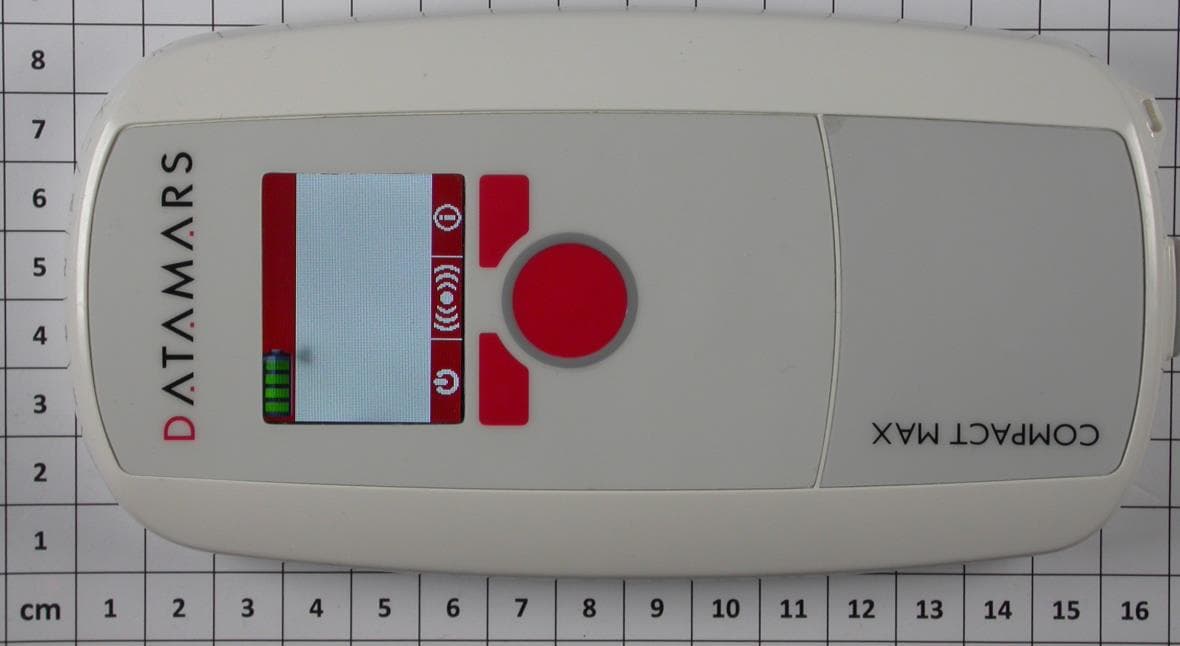
NDX-COMPACTMAX
Aug 17, 2014RFID handheld reader for animal indentification
Equipment Class
DCD - Part 15 Low Power Transmitter Below 1705 kHz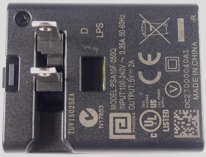
NDX-OMNIMAX
Jan 19, 2014RFID handheld reader for livestock applications
Equipment Class
JBP - Part 15 Class B Computing Device Peripheral