NEX-1081-493" R/C Micro Polaris MSX Watercraft 1081
Zaptoys International Limited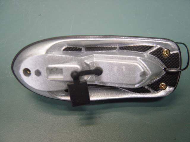
Click to zoom
Application Details
- Equipment Class
- CRR - Superregenerative Receiver
- Date of Grant
- May 16, 2004
- Application Purpose
- Original Equipment
- Date of Application
- May 16, 2004
- Equipment Note
- 3" R/C Micro Polaris MSX Watercraft 1081
- Frequency Range
- 49.86000000 - 49.86000000
- Country
- Hong Kong
Documents & Files
Document Text
Text extracted from the exhibit documents filed with the FCC. Open a document above to read the original.
Users Manual
Mico Watercraft Please read through this instruction manual carefully before starting to operate. Please ensure to remove all accessories and components f rom packaging. 1. Disconnect transmitter into 2 separate units. The c harger is the unit with 3 X AAA (1.5V) batteries installed. 2. Unplug the boat's charging socket cover. 3. Insert the charger into the charging socket. 4. When green light on the charger goes out, boat is cha rged. 5. Remove the charger, and re-plug the boat socket cover t o pre ven t water from entering. 1. Re-connect the charger unit into the transmitter to bec ome a tran smi tte r un it. 2. Extend the transmitter antenna to its fu ll length. 3. Press buttons at both sides of the transmitter to pop up the cover to show control buttons. 4. Before racing your boat, make sure that the antenna is stan ding verti cally upright for better signal receiving. make sure the charging connector is in-line with the boat so cket, incorrect insertion will damage the charging socket. Attention : HELPFUL HINTS: - Do n ot e x p ose the bo a t t o extr e m e tempe r at u r es. - If th e b oa t do e s n ot r e s p on d to the tr ans m i tte r , move closer to th e b oa ts a nd try ag a i n . - If th e b oa t star ts to lose po wer . I t may exp eri e nce l oss of perfo r m an ce a bil i ty. I f t his happe ns. si m ply r ech arge yo ur b oa t a ga i n. - Whe n th e tr a nsm i tte r ran g e d ecr e ase s, replace th e ba tt er y in the co nt r oll e r . MAIN T ENANC E AN D CAR E: - If th e b oa t be co m es di r ty, u s e a s l i gh tly d a m p en e d cl ot h to wi pe o ff th e d i r t a nd f i l th . Th e n u se a d r y cl o th to w i pe o ff th e m o i sture. - To remove du st p arti cl es, tie a sm a l l b i t of cl oth to the tip o f a to o th pick , t weeze r s, e tc, an d wi p e of f . - Do n ot u s e ch e m i cals . The b od y of th e bo at ca n m elt a n d ca use m a chi n e tr oubl es. - Be su r e of r e m o v e th e b a tte r i es fr om th e tr an sm i tte r w h en sto r i ng th e p r oduct a way. - Ke ep th i s In str u cti o n M an u al ca r efu l l y for fut ure use . TROUBLE S H O OTIN G Instruction Manual #1081 1.What is in the package 2. Battery installation 3. Charging Your Micro Boat 4. Racing Your Micro Boat 5. How to play Another Quality Product From QUALITY TOYSQUALITY TOYS THIS PRODUCT IS FOR THE USE IN U.K., SPAIN, GERMANY, FRANCE, BELGIUM, ITALY, SWITZERLAND, THE NETHERLANDS, DENMARK, U.S., CANADA AND PORTUGAL. Recommended to use alkaline batteries for best performance, 3 X AAA (1.5V) batteries. (included) NOTE: This equipment has been tested and found to comply with the limits for a Class B digital device, pursuant to Part 15 of FCC Rules and R&TTE Directive 1999/5/EC.These limits are designed to provide reasonable protection against harmful interference in a residential installation. This equipment generates, uses and can radiate radio frequency energy and, if not installed and used in accordance with the instructions, may cause harmful interference the radio communications.However, there is no guarantee that interference will not occur in a particular installation. If this equipment does cause harmful interference to radio or television reception, which can be determined by turning the equipment off and on, the user is encouraged to try to correct the interference by one or more of the following measures: - Reorient or relocate the receiving antenna. - Increase the separation between the equipment and receiver. - Connect the equipment into an outlet on a circuit different from that to which the receiver is needed. - Consult the dealer or an experienced radio/TV technician for help. pri nt e d in c hina 0197 NO Engl i sh . 1081 © ZA PTO Y S 2004 M A D E I N CH I NA Warning: C h ang es o r m o d i f i c at ion s to t h is un it n o t ex p r essly ap p r oved by th e par t y r esp o n sib l e fo r co m p li a n c e co u ld void t h e user ' s a u t h o r i t y t o o p er at e th e e q uip me n t Transmitter Stand 1. Remove battery compartment cover located on the back of the transmitter. 2. Insert 3 X AAA (1.5V) batteries into the transmitter following the +/- marking. 3. Replace the battery cover. Manual 1 & 3 2 1 & 4 green light 1 green light 2 charging socket connection button button control buttons 3 Problem Boat drives slowly Poor range control Cause - Weak rechargeable batteries in the boat. - Weak batteries in transmitter - Strong interference at the surrounded area. Correction - Recharge the boat with the charger. - Replace with new batteries - Move to a better location to drive your boat. CAUTION: - Do n ot o pe r at e you r b o at whe r e the r e ar e wate r p l an ts, r u bb i sh, fil th, o r o th er ob stacles i n th e p o nd . - Do n ot p l a y w h ere th e wate r cu r r e nt is str on g or whe n the w i nd i s blowi ng str o ng l y. - Do n ot p l a y i n o cea n wate r , becau se salt wate r ca n cau se r usti n g. - Do n ot p l a y i n th e th u nd erstor m s. - It is extrem ely d angerou s to to uch th e pr o pe l l e r w h i l e i t is spinn i ng. - Th e toy i s d e s i gned for i n do o r u se o nl y. Ou td o ors use m ay l e ad t o m a l fu nction ca use d by d i r t o r waste . - Non - r e cha r ge a ble b att eri e s a r e n ot to b e r e c h arge d - Rech a r ge ab l e ba tte r i es are to b e r emove d fr o m the toy b e i ng cha r ged, - Rech a r ge ab l e ba tte r i es are on l y to be c h arge d un d er a du l t sup e r vi si on, - Di ffe r e nt type s o f ba tte r i es or n ew a n d use d b at teri e s a r e n ot to be m i xed - O n l y b att eri e s o f the sa m e o r e q uiv a l e nt type a s r eco m m en d ed ar e to be u sed . - B a tte r i es ar e to be i nse r te d with the cor r e c t po l ari ty. - E xha uste d b a tte r i es ar e to be r emove d from th e to y - Th e sup p l y te r m i n als are no t t o be sho r t- ci r cuited . - Th e toy i s to be op e r at e d i n w a ter on l y whe n fu l l y asse m bled Micro Polaris Wat…
Text truncated - open the document above for the full version.
Block Diagram
TÜV Rheinland Product Safety GmbH Am Grauen Stein D - 51105 Köln Appendix 5 Prüfbericht - Nr.: Test Report No. 14005576 001 Seite 1 von 4 Page 1 of 4
External Photos
TÜV Rheinland Product Safety GmbH Am Grauen Stein D - 51105 Köln Appendix 3 Prüfbericht - Nr.: Test Report No. 14005576 001 Seite 1 von 1 Page 1 of 1
ID Label/Location Info
TÜV Rheinland Product Safety GmbH Am Grauen Stein D - 51105 Köln Appendix 5 Prüfbericht - Nr.: Test Report No. 14005576 001 Seite 3 von 4 Page 3 of 4
Internal Photos
TÜV Rheinland Product Safety GmbH Am Grauen Stein D - 51105 Köln Appendix 4 Prüfbericht - Nr.: Test Report No. 14005576 001 Seite 1 von 3 Page 1 of 3 TÜV Rheinland Product Safety GmbH Am Grauen Stein D - 51105 Köln Appendix 4 Prüfbericht - Nr.: Test Report No. 14005576 001 Seite 2 von 3 Page 2 of 3 TÜV Rheinland Product Safety GmbH Am Grauen Stein D - 51105 Köln Appendix 4 Prüfbericht - Nr.: Test Report No. 14005576 001 Seite 3 von 3 Page 3 of 3
Operational Description
FCCID: NEX-1081-49 1. Operation Description The equipment under test ( EUT) is a RC toy Boat operating at 49.860MHz. The forward, backward, left and right movement are controlled by the associated transmitter. 2. Circuit Description 1) Q1 and the associated circuit act as a RF-receiver. 2) IC1 and the associated circuit act an AF amplifier. 3) Q2-Q7 and the associated circuit act as a power amplifier for DC motor.
Schematics
TÜV Rheinland Product Safety GmbH Am Grauen Stein D - 51105 Köln Appendix 5 Prüfbericht - Nr.: Test Report No. 14005576 001 Seite 2 von 4 Page 2 of 4
Test Report
TÜV Rheinland Product Safety GmbH Am Grauen Stein D - 51105 Köln Prüfbericht - Nr.: Test Report No. 14005576 001 Seite 2 von 11 Page 2 of 11 TEST SUMMARY 7.1.1 S PURIOUS RADIATED EMISSIONS Resullt: Pass TÜV Rheinland Product Safety GmbH Am Grauen Stein D - 51105 Köln Prüfbericht - Nr.: Test Report No. 14005576 001 Seite 3 von 11 Page 3 of 11 Contents 1 GENERAL REMARKS...........................................................................................................4 1.1 COMPLEMENTARY MATERIALS..........................................................................................4 2 TEST SITES..........................................................................................................................4 2.1 TEST FACILITIES.................................................................................................................4 2.2 LIST OF TEST AND MEASUREMENT INSTRUMENTS............................................................5 3 GENERAL PRODUCT INFORMATION...................................................................................6 3.1 PRODUCT FUNCTION AND INTENDED USE..........................................................................6 3.2 CIRCUIT DESCRIPTION........................................................................................................6 3.3 RATINGS AND SYSTEM DETAILS.........................................................................................6 3.4 INDEPENDENT OPERATION MODES....................................................................................7 3.5 SUBMITTED DOCUMENTS....................................................................................................7 3.6 RELATED SUBMITTAL(S) GRANTS......................................................................................7 4 TEST SET-UP AND OPERATION MODE................................................................................8 4.1 PRINCIPLE OF CONFIGURATION SELECTION.....................................................................8 4.2 TEST OPERATION AND TEST SOFTWARE............................................................................8 4.3 SPECIAL ACCESSORIES AND AUXILIARY EQUIPMENT.......................................................8 4.4 C OUNTERMEASURES TO ACHIEVE EMC COMPLIANCE.....................................................8 5 T EST METHODOLOGY.........................................................................................................9 6 FIELD STRENGTH CALCULATION.......................................................................................9 7 TEST RESULTS...................................................................................................................10 7.1.1 Spurious Radiated Emissions ................................................................................................................... 10 TÜV Rheinland Product Safety GmbH Am Grauen Stein D - 51105 Köln Prüfbericht - Nr.: Test Report No. 14005576 001 Seite 4 von 11 Page 4 of 11 1 General Remarks 1.1 Complementary Materials All attachments are integral parts of this test report. This applies especially to the following appendix: Appendix 1: Test Results Appendix 2: Test Setup Appendix 3: External Photographs of EUT Appendix 4: Internal Photographs of EUT Appendix 5: FCCID Label, Block Diagram, Schematics and User Manual 2 Test Sites 2.1 Test Facilities Hong Kong Productivity Council HKPC Building 78 Tat Chee Avenue Kowloon Hong Kong TÜV Rheinland Product Safety GmbH Am Grauen Stein D - 51105 Köln Prüfbericht - Nr.: Test Report No. 14005576 001 Seite 5 von 11 Page 5 of 11 2.2 List of Test and Measurement Instruments Table 1: List of Test and Measurement Equipment Kind of Equipment Manufacturer Type S/N Test Receiver Rohde & Schwarz ESH-3 890173/033 L/I/S/N Rohde & Schwarz ESH 3-Z5 849876/026 Oscilloscope HP 54713B US34510455 Test Receiver Rohde & Schwarz ESVP 882402/033 Absorbing Clamp Rohde & Schwarz MDS-21 979 3/4 Test Receiver Rohde & Schwarz ESVS30 842807/009 Biconical Antenna Rohde & Schwarz HK116 841489/015 Log.-Periodic Antenna Rohde & Schwarz HL223 841516/017 Universal Power Analyzer Voltech PM3000A 9915 Reference Impedance Network Voltech IEC 555 Standard 9946 AC Power Source California Instr. 4500L HK51895 Trip-Loop Antenna Chase LLA6142 1019 Double Ridge Horn Antenna EMCO 3115 9002-3351 Double Ridge Horn Antenna EMCO 3116 9002-3347 RF Comms Test Set HP 8920B US36492628 Spectrum Analyser + Tracking Gen. HP 8596E 3639A00758 Signal Generator Rohde & Schwarz SMY 01 844146/024 Signal Generator Rohde & Schwarz SMY 01 844146/023 BiLog Antenna EMCO 3143 9607-1287 Isotropic Field Probe Holladay HI-4422 90956 Power Amplifier Kalmus 757-LC 7620-1 Power Amplifier Kalmus 122-FC 7620-2 Coupling Clamp Schaffner CDN 126 312 Couple Device Network Fischer CDN-M2 9604 Spectrum Analyzer Rohde & Schwarz FSP30 1093.4495K30 Temperature Chamber Binder MK 240 9020-0028 EFT,ESD,SURGE, DIPS tester Schaffner Best 96 IN3796-011 TÜV Rheinland Product Safety GmbH Am Grauen Stein D - 51105 Köln Prüfbericht - Nr.: Test Report No. 14005576 001 Seite 6 von 11 Page 6 of 11 3 General Product Information 3.1 Product Function and Intended Use The equipment under test ( EUT) is a RC toy boat operating at 49.860MHz. The forward, backward, left and right movement are controlled by the associated transmitter. After construction checking and declaration from the manufacturer, it is deemed that that 1082 and 1083 are same in circuit design and PCB layout as 1081, they only differ in the cosmetic design. Hence, all testing was conducted on the representative model: 1081. FCCID: NEX-1081-49 Model Product description 1081 3” R/C Polaris MSX Watercraft 1082 3” R/C Micro Boat 1083 3” R/C Cabin Cruisers 3.2 Circuit Description 1) Q1 and the associated circuit act as a RF-receiver. 2) IC1 and the associated circuit act an AF amplifier. 3) Q2-Q7 and the associated circuit act as a power amplifier for DC motor. 3.3 Ratings and System Detai…
Text truncated - open the document above for the full version.
Test Report
TÜV Rheinland Product Safety GmbH Am Grauen Stein D - 51105 Köln Appendix 1 Prüfbericht - Nr.: Test Report No. 14005576 001 Seite 1 von 4 Page 1 of 4 TÜV Rheinland Product Safety GmbH Am Grauen Stein D - 51105 Köln Appendix 1 Prüfbericht - Nr.: Test Report No. 14005576 001 Seite 2 von 4 Page 2 of 4 TÜV Rheinland Product Safety GmbH Am Grauen Stein D - 51105 Köln Appendix 1 Prüfbericht - Nr.: Test Report No. 14005576 001 Seite 3 von 4 Page 3 of 4 TÜV Rheinland Product Safety GmbH Am Grauen Stein D - 51105 Köln Appendix 1 Prüfbericht - Nr.: Test Report No. 14005576 001 Seite 4 von 4 Page 4 of 4
Contact Information
Applicant
John Kin Jok(Sales Executive)
Technical Contact
T�V Rheinland Hong Kong Ltd.Prudence Poon
[email protected]+852 2192 1000
Unit 8, 25/F., Skyline Tower · Hong Kong · Hong Kong
Non-Technical Contact
T�V Rheinland Hong Kong Ltd.Prudence Poon
[email protected]+852 2192 1000
Test Firm
Hong Kong Productivity CouncilIr Angel Wong Yuen-yee
Technical Specifications
| # | Rule Parts | Frequency Range | Power Output |
|---|---|---|---|
| 1 | 15B | 49.86 MHz - 49.86 MHz | - |
Other Applications from Zaptoys International Limited

NEX-9590D-27TX
Jul 12, 2011RC Toy Transmitter
Equipment Class
DXX - Part 15 Low Power Communication Device Transmitter
NEX-9650-27TX
May 19, 2011RC Toy Transmitter
Equipment Class
DXX - Part 15 Low Power Communication Device Transmitter
NEX-9651-27TX
May 03, 2011RC Toy Transmitter
Equipment Class
DXX - Part 15 Low Power Communication Device Transmitter
NEX-9344D27TX
Apr 20, 2010Radio Control Toy Transmitter
Equipment Class
DXX - Part 15 Low Power Communication Device Transmitter
NEX-9398637D
Apr 07, 2010RC Toy Transmitter
Equipment Class
DXX - Part 15 Low Power Communication Device Transmitter