NGVAWX701TXIR RF Remote Control Extender TX
Airwave Technologies Inc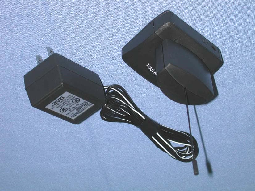
Click to zoom
Application Details
- Equipment Class
- DSC - Part 15 Security/Remote Control Transmitter
- Date of Grant
- Apr 10, 2003
- Application Purpose
- Original Equipment
- Date of Application
- Apr 10, 2003
- Equipment Note
- IR RF Remote Control Extender TX
- Frequency Range
- 418.00000000 - 418.00000000
- Company
- Airwave Technologies Inc
- Country
- Taiwan
Documents & Files
Document Text
Text extracted from the exhibit documents filed with the FCC. Open a document above to read the original.
Users Manual
Remote Control Extender A UDIO / V IDEO D EVICES E XTENDING S YSTEM M ODEL NO.: AWX 701-A/AWX 701-B/AWX 701-C OPERATION MANUAL Remote Control Extender A UDIO / V IDEO D EVICES E XTENDING S YSTEM M ODEL NO.: AWX 701-A/AWX 701-B/AWX 701-C OPERATION MANUAL INTRODUCTION Your Wireless Infrared Extender Kit consists of a transmitter base unit which receives the IR signal from your infrared controller, and a receiver unit which transmits the IR control signal to your household appliances such as LD and/or VCR systems in another room without cable. The main function of IR extender is to convert the infrared signal into a radio frequency signal, which can extend the effective range of the existing infrared controller through walls, ceiling, or floor. Thus, you can control your household appliances such as TV, VCR, LD, VCD, and Cable Box ... from anywhere at home wirelessly. To adopt with Video Sender system in addition will enhance the remote control function and make your life more convenient and practical. WARNING: To reduce the risk of fire or electric shock, do not expose this product to rain or moisture. CAUTION RISK OF ELECTRIC SHOCK DO NOT OPEN CAUTION: TO REDUCE THE RISK OF ELECTRIC SHOCK, DO NOT REMOVE COVER (OR BACK) NO USER-SERVICEABLE PARTS INSIDE REFER SERVICING TO QUALIFIED SERVICE PERSONNEL SAFETY INSTRUCTIONS 1. Read Instructions - All the safety and operating instructions should be read before the product is operated. 2. Retain Instructions - The safety and operating instructions should be kept for future reference. 3. Heed Warnings - All warnings on the product and in the operating instructions should be adhered to. 4. Follow Instructions - All operating and use instructions should be followed. 5. Cleaning - Unplug this product from the wall outlet before cleaning. Do not use liquid cleaners or aerosol cleaners. Use a damp cloth for cleaning. 6. Attachments - Do not use attachments not recommended by the product manufacturer as they may cause hazards. 7. Water and Moisture - Do not use this product near water - for example, near a bath tub, wash bowl, kitchen sink, or laundry tub, in a wet basement, or near a swimming pool; and this like. 8. Accessories - Do not place this product on an unstable cart, stand, tripod, bracket, or table. The product may fall, causing serious injury to a child or adult, and serious damage to the product. Use only with a cart, stand, tripod, bracket, or table recommended by the manufacturer, or sold with the product. Any mounting of the product should follow the manufacturer‘s instructions, and should use a mounting accessory recommended by the manufacturer. 9. A product and cart combination should be moved with care. Quick stops, excessive force and uneven surfaces may cause the product and cart combination to overturn. 1 10. Ventilation - Slots and openings in the cabinet are provided for ventilation and to ensure reliable operation of the product and to protect it from overheating, and these openings must be blocked or covered. The openings should never be blocked by placing the product on a bed, sofa, rug, or other similar surface. This product should not be placed in a built-in installation such as a bookcase or rack unless proper ventilation is provided or the manufacturer‘s instructions have been adhered to. 11. Power Sources - This product should be operated only from the type of power source indicated on the marking label. If you are not sure of the type or power supply to your home, consult your product dealer or local power company. For products intended to operate from battery power, or other sources, refer to the operating instructions. 12. Power-Cord Protection - Power supply cords should be routed so that they are not likely to be walked on or pinched by items placed upon or against them, paying particular attention to cords at plugs, convenience receptacles, and the point where they exit from the product. 13. Lightning - For added protection for this product during a lightning storm, or when it s is left unattended and unused for long periods of time, unplug it from the wall outlet and disconnect the antenna or cable system. This will prevent damage to the product due to lightning and power-line surges. 14. Overloading - Do not overload wall outlets, extension cords, or integral convenience receptacles as this can result in a risk of fire or electric shock. 15. Object and Liquid Entry - Never push objects of any kind into this product through openings as they may touch dangerous voltage points or short-out parts that could result in a fire or electric shock. Never spill liquid of any kind on the product. 16. Servicing - Do not attempt to service this product yourself as opening or removing covers may expose you to dangerous voltage or other hazards. Refer all servicing to qualified service personnel. 2 17. Damage Requiring Service - Unplug this product from the wall outlet and refer servicing to qualified service personnel under the following conditions: 18. When the power-supply cord or plug is damaged, 19. If liquid has been spilled, or objects have fallen into the product, 20. If the product has been exposed to rain or water, 21. If the product does not operate normally by following the operating instructions. Adjust only those controls that are covered by the operating instructions as an improper adjustment of other controls may result in damage and will often require extensive work by a qualified technician to restore the product to its normal operation, 22. If the product has been dropped or damaged in any way, and 23. When the product exhibits a distinct change in performance - this indicates a need for service. 24. Heat - The product should be situated away from heat sources such as radiators, hear registers, stoves, or other products including amplifiers that produce heat. Infrared Remote Control Extender Units Transmitter unit Receiver unit Antenna Purple semitransparent window 3 Installation of IR Extender: 1. Power Supply …
Text truncated - open the document above for the full version.
Block Diagram
1234123 4 DCBA BCD A PAGE REV. DWG TITLE DWG NO. SIZE DRAW BYENG. BYISSUED BY AIRWAVE TECHNOLOGIES INC. ENGINEER DATE DESCRIPTION ECN NO. REV. REVISIONS of Error : Awlogo.bmp file not found. A 1 1 L.H.SL.H.S ( 433.92 MHz) AWX701TX BLOCK Diagram 418MHz ASK Mixer ANTENNA IR Receiver IR 418MHz Oscillator IR TO RF IR Remote Controller (1) Power Supply VCC DC TX-Amp Filter (2) (3) (4) (5) (6) AWX701TX
External Photos
Report No.: 033H057FI Page : 1 of 9 Version:1.0 Attachment 2 : EUT Detailed Photographs M/N: AWX701TX, AWX701-A (1) EUT Photo (2) EUT Photo Report No.: 033H057FI Page : 8 of 9 Version:1.0 N/M:AWX701-B (12) EUT Photo (13) EUT Photo Report No.: 033H057FI Page : 9 of 9 Version:1.0 N/M:AWX701-C (14) EUT Photo (15) EUT Photo
ID Label/Location Info
AIRWAVE TECHNOLOGIES INC. FCC ID.: NGVAWX701TX 3F, NO.9,INDUSTRY E. RD. IX, SCIENCE-BASED INDUSTRIAL PARK, HSINCHU, TAIWAN, R.O.C Tel: 03-5778099 FCC ID The FCC ID will be placed on the equipment as shown in the photograph below. IR RF Remote Control Extender TX Model No.: AWX701TX, AWX701-A, AWX701-B, AWX701-C F F C C C C I I D D : : N N G G V V A A W W X X 7 7 0 0 1 1 T T X X This device complies with Part 15 of the FCC Rules. Operation is subject to the following two conditions: (1) this device may not cause harmful interference and (2) this device must accept any interference received, including interference that may cause undesired operation. S/N: Made in Taiwan
ID Label/Location Info
AIRWAVE TECHNOLOGIES INC. FCC ID.: NGVAWX701TX 3F, NO.9,INDUSTRY E. RD. IX, SCIENCE-BASED INDUSTRIAL PARK, HSINCHU, TAIWAN, R.O.C Tel: 03-5778099 FCC ID The FCC ID will be placed on the equipment as shown in the photograph below. IR RF Remote Control Extender TX Model No.: AWX701TX, AWX701-A, AWX701-B, AWX701-C F F C C C C I I D D : : N N G G V V A A W W X X 7 7 0 0 1 1 T T X X This device complies with Part 15 of the FCC Rules. Operation is subject to the following two conditions: (1) this device may not cause harmful interference and (2) this device must accept any interference received, including interference that may cause undesired operation. S/N: Made in Taiwan
Internal Photos
Report No.: 033H057FI Page : 2 of 9 Version:1.0 (3) EUT Photo (4) EUT Photo Report No.: 033H057FI Page : 3 of 9 Version:1.0 (5) EUT Photo Report No.: 033H057FI Page : 4 of 9 Version:1.0 (6) EUT Photo Report No.: 033H057FI Page : 5 of 9 Version:1.0 (7) EUT Photo Report No.: 033H057FI Page : 6 of 9 Version:1.0 (8) EUT Photo (9) EUT Photo Report No.: 033H057FI Page : 7 of 9 Version:1.0 (10) EUT Photo (11) EUT Photo
Operational Description
Report No. 033H057FI Page : 1 of 1 Version:1.0 1.1. Operation Description The EUT is a 418MHz transmitter. The infrared remote control signal can be transferred to 418MHz radio frequency in ASK modulation. The transmission antenna is soldered on the EUT.
Schematics
1234123 4 DCBA BCD A PAGE 1 REV. 1 DWG TITLE A DWG NO. SIZE DRAW BYENG. BYISSUED BY AIRWAVE TECHNOLOGIES INC. ENGINEER DATE DESCRIPTION ECN NO. REV. REVISIONS of Error : Awlogo.bmp file not found. L.H.SL.H.S AWX701TX Circuit VCC C100.1u L2 107nH L144nH 1 23 Q2BFS520 1 23 Q1 BFS520 2 1 3 Q33906 R134.7K R510 C7100P C13100P ANTENNA C8100P R103K9 C6100P R7200RR61K8 C4100P C38PC512P R210R3180 C2100P R110K C1100P 2 1 3 418MHz SAW RESONATOR C90.1u 2 1 3 UIR-RECV VCC R161K LED1RED Vin 1 GND 3 +5V 2 U1 78L05 DC+9V 5V TC2 N/A C125P L4 25nH C1412P L5 29nH C1512P L3 25nH VCC TC1 10uF/16V C17 100P C16 100P Test Point R2262R R2062R C185P C116P R11910R R140R R12 5.6R R210 Test Point R15910R Test Point Test Point Test Point R23N/A C231nF C22100P R510R R500R R400R AWX701TX (US)Circuit
Test Report
Report No. 033H057FI Page : 1 of 23 Version:1.0 Test Report Product Name : IR RF Remote Control Extender TX Model No. : AWX701TX, AWX701-A, AWX701-B, AWX701-C FCC ID.: NGVAWX701TX Applicant : AIRWAVE TECHNOLOGIES INC. Address : 3F, NO.9,INDUSTRY E. RD. IX, SCIENCE-BASED INDUSTRIAL PARK, HSINCHU, TAIWAN, R.O.C Date of Receipt : Mar 13, 2003 Date of Test : Apr 08, 2003 Report No. : 033H057FI The Test Results relate only to the samples tested. The test report shall not be reproduced except in full without the written approval of QuieTek Corporation. This report must not be used to claim product endorsement by NVLAP any agency of the U.S. Government Report No. 033H057FI Page : 3 of 23 Version:1.0 TABLE OF CONTENTS Description Page 1. GENERAL INFORMATION..............................................................................................................4 1.1. EUT Description ....................................................................................................................................4 1.2. Operation Description ............................................................................................................................4 1.3. Tested System Details ............................................................................................................................5 1.4. Configuration of Tested System.............................................................................................................5 1.5. EUT Exercise Software..........................................................................................................................5 1.6. Test Facility ............................................................................................................................................6 2. Conducted Emission ............................................................................................................................7 2.1. Test Equipment ......................................................................................................................................7 2.2. Test Setup ...............................................................................................................................................7 2.3. Limits .....................................................................................................................................................7 2.4. Test Procedure ........................................................................................................................................8 2.5. Test Result of Conducted Emission .......................................................................................................9 3. Radiated Emission.............................................................................................................................. 11 3.1. Test Equipment ....................................................................................................................................11 3.2. Test Setup .............................................................................................................................................11 3.3. Limits ...................................................................................................................................................12 3.4. Test Procedure ......................................................................................................................................13 3.5. Test Result of Radiated Emission ........................................................................................................14 4. Occupied Bandwidth..........................................................................................................................17 4.1. Test Equipment ....................................................................................................................................17 4.2. Test Setup .............................................................................................................................................17 4.3. Limits ...................................................................................................................................................17 4.4. Test Result of Occupied Bandwidth.....................................................................................................18 5. Duty Cycle...........................................................................................................................................19 5.1. Test Equipment ....................................................................................................................................19 5.2. Test Setup .............................................................................................................................................19 5.3. Test Result of Duty Cycle ....................................................................................................................20 6. EMI Reduction Method During Compliance Testing .....................................................................21 Attachment 1: EUT Test Photographs Attachment 2: EUT Detailed Photographs Report No. 033H057FI Page : 4 of 23 Version:1.0 1. GENERAL INFORMATION 1.1. EUT Description Product Name : IR RF Remote Control Extender TX Trade Name : AIRWAVE FCC ID. : NGVAWX701TX Model No. : AWX701TX, AWX701-A, AWX701-B, AWX701-C Type of Modulation : ASK Antenna type : Soldered on PCB Operating Frequency : 418 MHz Operator Selection of Operating Frequency : Not Applied IR (Rx) : 1 Set, Non-Shielded, 3m Power Adapter : DVE, DV-9100S, 2Pcs Cable Out: Non-Shielded, 1.7m Note: 1. This device is a 418MHz IR RF Remote Control Extender TX included a 418MHz transmitting function. 2. The variation of model number is for different outlook. The circuit of each model is identical. 3. These tests were conducted on a sample of the equipment for the purpose of demonstrati…
Text truncated - open the document above for the full version.
Test Setup Photos
Report No.: 033H057FI Page : 1 of 3 Version:1.0 Attachment 1: EUT Test Setup Photographs Front View of Conducted Test Back View of Conducted Test Report No.: 033H057FI Page : 2 of 3 Version:1.0 Front View of Radiated Test Back View of Radiated Test Report No.: 033H057FI Page : 3 of 3 Version:1.0 Front View of Radiated Test (Horn)
Contact Information
Applicant
Tzu-Hung Chen(President)
Test Firm
DEKRA Testing and Certification Co., Ltd.Sky Hsu
Technical Specifications
| # | Rule Parts | Frequency Range | Power Output |
|---|---|---|---|
| 1 | 15.231 | 418 MHz - 418 MHz | - |
Other Applications from Airwave Technologies Inc
NGVAWS821T
Apr 23, 2012Wire-to-Air
Equipment Class
DTS - Digital Transmission System
NGVAWS822R
Apr 23, 2012Wire-to-Air
Equipment Class
DTS - Digital Transmission System
NGVAWD8112
Apr 18, 2012Wire-to-Air
Equipment Class
DSS - Part 15 Spread Spectrum Transmitter
NGVAWP30XA
Sep 12, 20102.4GHz WIRELESS USB ADAPTOR
Equipment Class
DXX - Part 15 Low Power Communication Device Transmitter
NGVAWP305M
Sep 12, 20102.4GHz WIRELESS MULTIFUNCTION UFO PRESENTER AIR MOUSE
Equipment Class
DXX - Part 15 Low Power Communication Device Transmitter