NHS-PT456Wall Switch Transmitter
Powertech Industrial Co Ltd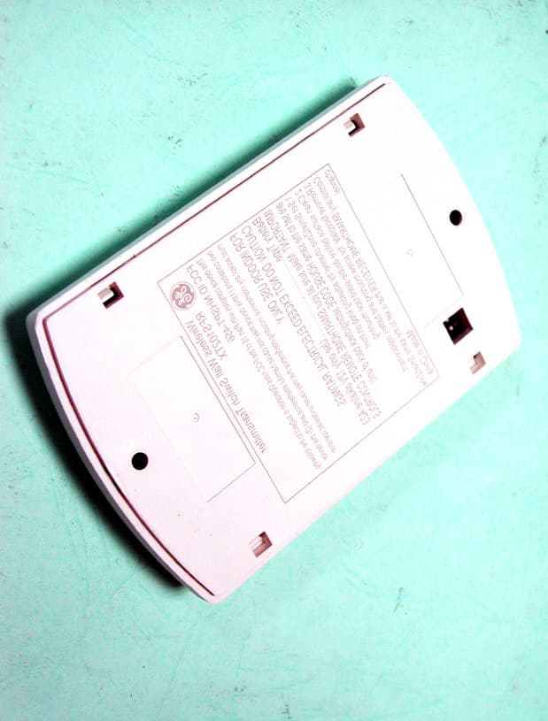
Click to zoom
Application Details
- Equipment Class
- DSC - Part 15 Security/Remote Control Transmitter
- Date of Grant
- Jan 29, 2003
- Application Purpose
- Original Equipment
- Date of Application
- Jan 29, 2003
- Equipment Note
- Wall Switch Transmitter
- Frequency Range
- 319.10000000 - 319.90000000
- Company
- Powertech Industrial Co Ltd
- Country
- Taiwan
Documents & Files
Document Text
Text extracted from the exhibit documents filed with the FCC. Open a document above to read the original.
Users Manual
CAUTION: Any changes of modifications not expressly approved by the grantee of this device could void the users authority to operate the equipment.
ID Label/Location Info
LABEL Size: 52 x 60 mm LABEL Format and Position: FCC ID: NHS−PT456 This device complies with Part 15 of the FCC Rules. Operation is subject to the following two conditions: (1) this device may not cause harmful interference, and (2) this device must accept any interference received, including interference that may cause undesired operation.
Test Report
Test Report ------------------------------------------------------------------------------- 1/16 Report No.: G2115230 (Tx) Training Research Co., Ltd., TEL: 886-2-26935155,Fax: 886-2-26934440 Report No. G2115230 Specifications FCC Part 15.231, Certification Test Method ANSI C63.4 1992 Applicant POWERTECH INDUSTRIAL CO., LTD. Applicant 10F, No. 403, Chang Shan Road, Sec. 2, Chung Ho City, address Taipei Hsien, Taiwan, R.O.C. Items tested Transmitter Model No. PT456A, PT456B (Sample # G21227) Results Compliance (As detailed within this report) Date 01/08/2003 (month / day / year) (Sample received) 01/08/2002 (month / day / year) (Test) Prepared by Project Engineer Authorized by General Manager (Frank Tsai) Issue date January 17, 2003 (month / day / year) Modifications None Tested by Training Research Co., Ltd. Office at 1F, No. 255, Nan Yang Street, Hsichih, Taipei Hsien 221, Taiwan Chamber at 1F, No. 255, Nan Yang Street, Hsichih, Taipei Hsien 221, Taiwan Conditions of issue: (1) This test report shall not be reproduced except in full, without written approval of TRC. And the test result contained within this report only relate to the sample submitted for testing. (2) This report must not be used by the client to claim product endorsement by NVLAP or any agency of U.S. Government. NVLAP LAB CODE: 200174-0 FCC ID: NHS−PT456 Test Report ------------------------------------------------------------------------------- 2/16 Report No.: G2115230 (Tx) Training Research Co., Ltd., TEL: 886-2-26935155,Fax: 886-2-26934440 Table of Contents CHAPTER 1 GENERAL..........................................................................3 1.1 INTRODUCTION...............................................................3 1.2 DESCRIPTION OF EUT......................................................3 1.3 DESCRIPTION OF SUPPORT EQUIPMENT............................3 1.4 TEST PROCEDURE...........................................................4 1.5 LOCATION OF THE TEST SITE...........................................4 1.6 GENERAL TEST CONDITION.............................................4 CHAPTER 2 TRANSMITTER DUTY CYCLE MEASUREMENTS.....5 2.1 TEST CONDITION AND SETUP..........................................5 2.2 LIST OF TEST INSTRUMENTS.............................................5 2.3 TEST INSTRUMENTS CONFIGURATION...............................6 2.4 TEST RESULT..................................................................6 CHAPTER 3 TRANSMITTER BANDWIDTH MEASUREMENTS, FCC PART 15.231(C)........................................................8 3.1 TEST CONDITION & SETUP..............................................8 3.2 TEST RESULT..................................................................8 CHAPTER 4 CONDUCTED EMISSIONS MEASUREMENTS..........10 4.1 TEST CONDITION..........................................................10 4.2 TEST RESULT................................................................10 CHAPTER 5 RADIATED EMISSIONS MEASUREMENTS...............11 5.1 GENERAL CONFIGURATION............................................11 5.2 TEST CONDITION AND SETUP........................................11 5.3 LIST OF TEST INSTRUMENTS...........................................13 5.4 TEST INSTRUMENTS CONFIGURATION.............................14 5.5 TEST RESULT OF RADIATED EMISSIONS..........................15 Table 1 Radiated Emissions for 30MHz to 3.5GHz [Horizontal, X-axis]....................................15 Table 2 Radiated Emissions for 30MHz to 3.5GHz [Horizontal, Y-axis]....................................15 Table 3 Radiated Emissions for 30MHz to 3.5GHz [Horizontal, Z-axis].....................................15 Table 4 Radiated Emissions for 30MHz to 3.5GHz [Vertical, X-axis]........................................16 Table 5 Radiated Emissions for 30MHz to 3.5GHz [Vertical, Y-axis]........................................16 Table 6 Radiated Emissions for 30MHz to 3.5GHz [Vertical, Z-axis]........................................16 Test Report ------------------------------------------------------------------------------- 3/16 Report No.: G2115230 (Tx) Training Research Co., Ltd., TEL: 886-2-26935155,Fax: 886-2-26934440 Chapter 1 GENERAL 1.1 Introduction The following measurement report is submitted on behalf of applicant in support of an International Periodic Radiator certification with Part 2 Subpart J and Part 15 Subpart A and C of the Commission's Rules and Regulations. 1.2 Description of EUT EUT : Transmitter Product Name : Wireless Wall-Screwing Transmitter Model No. : PT456A, PT456B FCC ID : NHS−PT456 Frequency Range : 319.10MHz ~ 319.90MHz Power Type : Powered by 12V/23A battery The fundamental frequency of transmitter emitted is due to a press on button of the EUT. The emitting time of fundamental frequency is less than 5 seconds pursuant to FCC Part 15.231(a). There are security codes for avoiding the possibility of duplicating codes in adjacent systems. The coding must be matching with the companion receiver. While testing the EUT was adjusted at a position, which transmits the maximum emission. 1.3 Description of Support Equipment No support equipment: The EUT itself forms a system. No support equipment is requited for its normal operation Test Report ------------------------------------------------------------------------------- 4/16 Report No.: G2115230 (Tx) Training Research Co., Ltd., TEL: 886-2-26935155,Fax: 886-2-26934440 1.4 Test Procedure All measurements contained in this report were performed according to the techniques described in measurement procedure of ANSI C63.4 1992 section 13 1.5 Location of the Test Site The radiated emissions measurements required by the rules were performed on the three-meter, Anechoic Chamber (Registration Number: 93906) maintained by Training Research Co., Ltd. 1F, No. 255, Nan Yang Street, Hsi-chih, Taipei Hsien 221, Taiwan, R.O.C. Complete description and measurement data have been placed on file with the commission. The conducted power line emis…
Text truncated - open the document above for the full version.
Test Setup Photos
Test Setup Photos ------------------------------------------------------------------------- 1/1 FCC ID: NHS-PT456 Training Research Co., Ltd., TEL: 886-2-26935155, Fax: 886-2-26934440 Radiated Test Setup Placement: (Worst case: Antenna Polarity Horizontal: X-axis, Antenna Polarity Vertical: Y-axis)
Contact Information
Applicant
George Lee(Manager)
Test Firm
Training Research Co., Ltd.Jack Tsai
Technical Specifications
| # | Rule Parts | Frequency Range | Power Output |
|---|---|---|---|
| 1 | 15.231 | 319.1 MHz - 319.9 MHz | - |
Other Applications from Powertech Industrial Co Ltd

NHS-EM3585
Dec 23, 2015Zigbee Module
Equipment Class
DTS - Digital Transmission System
NHS-A02A
Dec 17, 2014Mobile Accessory - Breathalyzer
Equipment Class
DTS - Digital Transmission System
NHS-R9P627
May 27, 2013APPS Power Control Timer Strip
Equipment Class
DSS - Part 15 Spread Spectrum Transmitter
NHS-R9P016
Sep 05, 2012ZigBee Tracking Energy Monitor
Equipment Class
DXX - Part 15 Low Power Communication Device Transmitter
NHS-M9PC02
Sep 03, 2012ZigBee Tracking Smart Socket
Equipment Class
DXX - Part 15 Low Power Communication Device Transmitter