NHSPTRX196Receiver to control remote power outlet
Powertech Industrial Co Ltd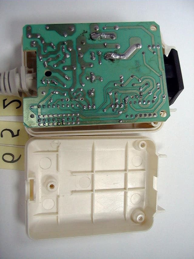
Click to zoom
Application Details
- Equipment Class
- CRR - Superregenerative Receiver
- Date of Grant
- Oct 21, 1999
- Application Purpose
- Original Equipment
- Date of Application
- Aug 22, 1999
- Equipment Note
- Receiver to control remote power outlet
- Frequency Range
- 314.67000000 - 314.67000000
- Company
- Powertech Industrial Co Ltd
- Country
- Taiwan
Documents & Files
Document Text
Text extracted from the exhibit documents filed with the FCC. Open a document above to read the original.
Users Manual
EXHIBIT C User Manual
Block Diagram
EXHIBIT E Block Diagram
External Photos
EXHIBIT F Photographs of EUT (Model No. : PTRX196) (Model No. : PTRX196) (Model No. : PTRX196) (Model No. : PTRX196) (Model No. : PTRX196) (Model No. : PTRX194) (Model No. : PTRX194) (Model No. : PTRX194) (Model No. : PTRX194) (Model No. : PTRX194)
ID Label/Location Info
EXHIBIT A Sample Label LABEL Format: This device complies with Part 15 of the FCC Rules Operation is subject to the following two conditions: (1) This device may not cause harmful interference, and (2) This device must accept any interference received, including interference that may cause undesired operation. FCC ID: NHSPTRX196 Model No.: PTRX196 LABEL Size : 4025 mm LABEL Position:
Schematics
EXHIBIT D Circuit Diagram
Test Report
EXHIBIT B Test Report Test Report------------------------------------------------------------------------------------------------------------ Report No.: G2115652, Receiver of Wireless Remote Outlet, FCC Part 15 Class B, Certification Test date: 08/10/99, Training Research Co., Ltd., TEL: 886-2-26935155,Fax: 886-2-26934440 2/15 Contents Chapter 1 Introduction Description of EUT..........................................................................................................3 Configuration of Test Setup..............................................................................................4 Chapter 2 Conducted Emission Test Test Condition and Setup.................................................................................................6 Conducted Test Placement...............................................................................................7 Chapter 3 Radiated Emission Test Test Condition and Setup.................................................................................................8 Radiated Test Placement..................................................................................................9 Appendix A: Conduction test result......................................................................................................10 Appendix B: Conduction test result ..............................................................................................................................12 Test Report------------------------------------------------------------------------------------------------------------ Report No.: G2115652, Receiver of Wireless Remote Outlet, FCC Part 15 Class B, Certification Test date: 08/10/99, Training Research Co., Ltd., TEL: 886-2-26935155,Fax: 886-2-26934440 3/15 Chapter 1Introduction Description of EUT: This device is a receiver of wireless remote outlet that connected with the AC power source and the transmittter will control the EUT to power on or power off the outlet. The largest difference between the two samples is PTRX194 has no power cable and PTRX196 has one short, extra power cable. Connection of EUT: (1) The Ac input jack of EUT is connected with the AC power source via an extending power outlet cable. (2) The AC outlet jack of EUT is connected with three 100W bulbs. Test method: When the receiver receives the signal, the bulbs will be on. When the receiver doesn’t receive the signal, the bulbs will not be on. Make sure the EUT is in “receiving” mode. There is a near field probe placed approximately to the EUT to radiate an unmodulated continuous wave (CW) signal to EUT at its operating frequency in order to “cohere” from such a receiver. The signal level may need to be increased for this to occur pursuant to FCC ANSI C63.4 Section 12.1.1.1. The amplitude and frequency of the signal was varied to yield the maximum emission. The test placement as the photographs showed is the worst case emission placed. (If the emission is close to the ambient, the resolution BW and view resolution will be reduced and the data will be recorded by detection of maximum hold peak mode.) Statement of transition provision for compliance with the rules The EUT receives the signal that only sends from the remote controller. The EUT won’t be influenced by the transition provision, it will be continuous comply with the regulations of the FCC Part 15. ( The relative remote controller FCC ID : NHSPTTX01). The testing configuration of test setup is showing in the next page. Test Report------------------------------------------------------------------------------------------------------------ Report No.: G2115652, Receiver of Wireless Remote Outlet, FCC Part 15 Class B, Certification Test date: 08/10/99, Training Research Co., Ltd., TEL: 886-2-26935155,Fax: 886-2-26934440 4/15 Configuration of test setup: Probe Power EUT To Far-End Signal Generator Extending power outlet cable Bulbs Connections: EUT: *AC In jack --- (1) directly connected with the AC power source (Model: PTRX194) (2) via a 30cm long, non-shielded, no ferrite bead, power cable to the AC power source via a extending power outlet cable. (Model: PTRXD196) *AC outlet jack--- via a 1.2m long, non-shielded, no ferrite bead, power cable to three 100W bulbs. Test Report------------------------------------------------------------------------------------------------------------ Report No.: G2115652, Receiver of Wireless Remote Outlet, FCC Part 15 Class B, Certification Test date: 08/10/99, Training Research Co., Ltd., TEL: 886-2-26935155,Fax: 886-2-26934440 5/15 List of support equipment Field Probe:HP Field Probe 30MHz~1GHz Model No. :HP11940A Serial No.: 2650A03038 Power type: by signal generator Data cable :1.8m long, non-shielded, no ferrite bead, Signal Generator: HP 9KHz~4000MHz Model No. : 8648D Serial No. : 3613A00117 Test Report------------------------------------------------------------------------------------------------------------ Report No.: G2115652, Receiver of Wireless Remote Outlet, FCC Part 15 Class B, Certification Test date: 08/10/99, Training Research Co., Ltd., TEL: 886-2-26935155,Fax: 886-2-26934440 6/15 Chapter 2Conducted emission test Test condition and setup: All the equipment is placed and setup according to the ANSI C63.4 - 1992. The EUT is assembled on a wooden table that is 80 cm high, is placed 40 cm from the back-wall that is a vertical conducting plane. One LISN is for EUT, the other LISN is for support equipment. They are all placed on the conductive ground. The EUT’s LISN connect a line switch box for selecting L1 or L2, then connect to a preamplifier and Spectrum. The spectrum scans from 450KHz to 30MHz. Conducted emission levels are detected at max. peak mode. But if the max. peak mode failed, it will be measured by CISPR‘s quasi-peak detection mode. While testing, there is the worst-emission plot printed at peak detection mode, and there are more than 6 highest emissions relative to limit recorded. The plot is kept as the origi…
Text truncated - open the document above for the full version.
Contact Information
Applicant
George Lee(Manager)
Technical Contact
Training Research Co., Ltd.Jack Tsai
[email protected]+886-2-2693-5155
2, Lane 194, Huan-Ho Street, Hsichih, Taipei Hsien · Taipei · Taiwan
Non-Technical Contact
Training Research Co., Ltd.Polly Chang
[email protected]+886-2-2693-5155
Technical Specifications
| # | Rule Parts | Frequency Range | Power Output |
|---|---|---|---|
| 1 | 15B | 314.67 MHz - 314.67 MHz | - |
Other Applications from Powertech Industrial Co Ltd

NHS-EM3585
Dec 23, 2015Zigbee Module
Equipment Class
DTS - Digital Transmission System
NHS-A02A
Dec 17, 2014Mobile Accessory - Breathalyzer
Equipment Class
DTS - Digital Transmission System
NHS-R9P627
May 27, 2013APPS Power Control Timer Strip
Equipment Class
DSS - Part 15 Spread Spectrum Transmitter
NHS-R9P016
Sep 05, 2012ZigBee Tracking Energy Monitor
Equipment Class
DXX - Part 15 Low Power Communication Device Transmitter
NHS-M9PC02
Sep 03, 2012ZigBee Tracking Smart Socket
Equipment Class
DXX - Part 15 Low Power Communication Device Transmitter