NL3GA0005DSSS Gas Meter Transmitter
NexusData Ltd.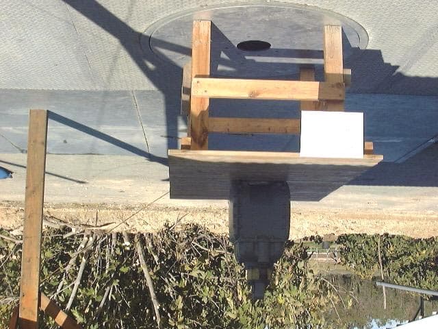
Click to zoom
Application Details
- Equipment Class
- DSS - Part 15 Spread Spectrum Transmitter
- Date of Grant
- Feb 28, 2001
- Application Purpose
- Original Equipment
- Date of Application
- Feb 28, 2001
- Equipment Note
- DSSS Gas Meter Transmitter
- Frequency Range
- 903.80000000 - 926.20000000
- Company
- NexusData Ltd.
- Country
- Israel
Documents & Files
Document Text
Text extracted from the exhibit documents filed with the FCC. Open a document above to read the original.
Users Manual
Nexus Data Industrial AMR Unit Installation and Initialization Manual General In order to comply with FCC RF Exposure requirements, the AMR unit must be installed in such a way that there is a 2m (6’ 8”) separation distance between it and all persons during normal operation. Assembly 1. Break seals. 2. Dismantle index cover, from meter (releasing 2 screws). 3. Dismantle old index, from meter (releasing 2 screws). 4. Dispose all old screws. 5. Connect index to AMR unit with 2 short screws, aligning the AMR unit’s shaft to the index’s shaft. 6. Place the AMR unit on the meter top, its label facing the front, and align its shaft with the meter shaft. By slightly rotating the shaft of the index, check that motion is transferred and that shafts are not stuck. 7. Holding the AMR unit’s position, place the index cover on top and assemble 2 long screws in index cover. The screws should fit through the AMR unit and into meter. 8. Tighten screws and seal with the red plastic seals. 9. Initialize the AMR unit using the MINT (handheld programmer): 9.1. Press 1 for WO (work order) by route to initializing the first AMR unit. 1. WO by route 2. Add WO 3. Read TX 4. Program TX 9.2. Select the Work Order and verify the details. Then key ENTER. 9.3. Select ‘4. CCF Reading’ and enter the number appearing on the index. 9.4. Press on the program key to initialize the AMR unit. FCC Warning Modifications not expressly approved by the manufacturer could void the user authority to operate the equipment under FCC Rules. WO: nnn/xxx > (APP) Loc: [decoded MeterLocation] Address: [first 63 characters of address] Meter: xxxyyyzzz 1. No. of Dials: 4 2. Index Drive: 1 3. Index Pressure: LP 4. CCF Reading: _ Exhibit 1 Exhibit 2
External Photos
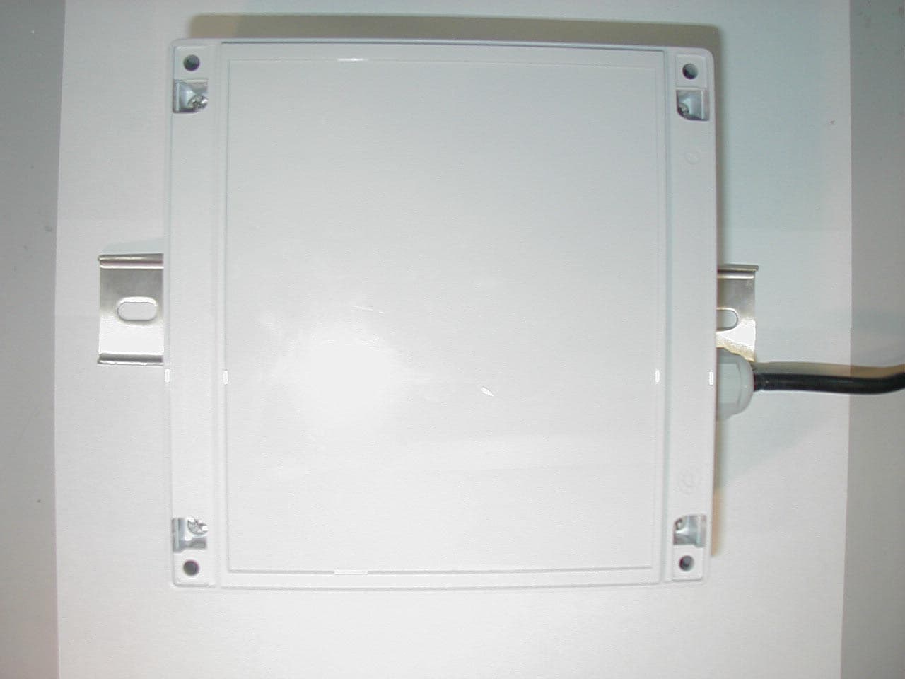
Figure 1. Radiated Emission Test. Front Figure 2. Radiated Emission Test. Side Figure 3 Front View Figure 4 Rear View Figure 5 Printed Circuit Side 1 Figure 6 Printed Circuit Side 2 Figure 7 Printed Circuit Mounted in Housing Figure 8 Housing External View
ID Label/Location Info
42mm 12mm Figure 1. FCC Label FCC ID: NL3GA0005 THIS DEVICE COMPLIES WITH PART 15 OF THE FCC RULES. OPERATION IS SUBJECT TO THE FOLLOWING TWO CONDITIONS: (1) THIS DEVICE MAY NOT CAUSE HARMFUL INTERFERENCE. (2) THIS DEVICE MUST ACCEPT ANY INTERFERENCE RECEIVED, INCLUDING INTERFERENCE THAT MAY CAUSE UNDESIRED OPERATION.
ID Label/Location Info
Figure 1. Location of Label on EUT
Internal Photos
Figure 1. Radiated Emission Test. Front Figure 2. Radiated Emission Test. Side Figure 3 Front View Figure 4 Rear View Figure 5 Printed Circuit Side 1 Figure 6 Printed Circuit Side 2 Figure 7 Printed Circuit Mounted in Housing Figure 8 Housing External View
Operational Description
NE US Gas Meter AMR Transmitter Technical description The GA-TX is a family of wireless end-point units (Transmitters) for gas utility Automated Meter Reading (AMR). These Transmitters are designed to operate in NexusData’s Fixnet TM , a highly economical fixed network configuration, achieving long coverage range while maintaining high reliability of the communication link. Transmitted messages contain meter reading, status and online alerts. Readings are transmitted periodically (typically daily), and status alert messages are transmitted immediately, once exception or tampering is detected. Transmitters are battery operated, with a typical battery life of over 10 years. The GA-TX is housed in a sealed, unobtrusive, waterproof enclosure, and is installed between the meter cast and the index. Its installation procedure is very simple since the Transmitter is delivered as a single-piece module. A separate, sealed and waterproof battery compartment is easily replaceable in the field by removing the index cover and sliding in a new battery pack in place of the old one. Initial settings (ID, Reading, etc.) are programmed to the GA-TX by using a handheld terminal with a wireless (magnetic loop) interface, eliminating the need to open its enclosure. Models of the GA-TX have been adapted to residential and industrial gas meters by American Meter, Invensys/Equimeter (Rockwell) and Schlumberger (Sprague). NE US Specification RF Output 30dBm (1 Watt) Range Urban area (typical) – 5-10 miles (8-16 km) Data Rate 4 Kbps Chip Rate 1 Mchips / sec Frequencies 903.8 – 926.2 MHz, 57 channels x 400 kHz steps Modulation Direct Sequence SP SP , BP SK PN Codes 255, maximal length sequence Configuration Storage Non-volatile memory Pow er Supply Lithium battery Pow er Consumption 750mA at transmission burst Less than 3μA – in power-down mode Battery Life (T ypical) Over 10 years for daily reads Operating Temperature -30°C to +80°C
Test Report
Electrical (EMC) Test Report E38950.00Nexus Data (1993) Ltd. Page 1 of 85 FCC ACC M Ver 1.1 05Mayl 2000 DATE: 15 January 2001 I.T.L. (PRODUCT TESTING) LTD. EMC Test for Nexus Data (1993) Ltd. Equipment under test: Gas Meter Industrial Approved by:__ ___________________________ I. Raz, EMC Laboratory Manager This report must not be reproduced, except in full, without the written permission of I.T.L. (Product Testing) Ltd. This report relates only to items tested. Electrical (EMC) Test Report E38950.00Nexus Data (1993) Ltd. Page 2 of 85 FCC ACC M Ver 1.1 05Mayl 2000 Measurement/Technical Report for Nexus Data (1993) Ltd. Gas Meter : Industrial FCC ID:NL3GA0005 15 January 2001 This report concerns:Original Grant x Class II change Class B verification Class A verification Class I change Equipment type: Radio Telemetry Transmitter Request Issue of Grant: x Immediately upon completion of review Limits used: CISPR 22 Part 15 x Measurement procedure used is ANSI C63.4-1992. Application for Certification Applicant for this device: prepared by:(different from "prepared by") Ishaishou RazShimon Zigdon ITL (Product Testing) Ltd.Nexus Data (1993) Ltd. Kfar Bin Nun16 Hamelacha St. D.N. Shimshon 99780Rosh Haayin 48091 IsraelIsrael e-mail [email protected]:+972- 903-2288 Fax:+972- 903-32299 e-mail: [email protected] Test Report E38950.00Nexus Data (1993) Ltd. Page 3 of 85 FCC ACC M Ver 1.1 05Mayl 2000 TABLE OF CONTENTS 1.GENERAL INFORMATION ------------------------------------------------------------------------------- 5 1.1Product Description ...........................................................................................5 1.2Test Methodology ..............................................................................................6 1.3Test Facility .......................................................................................................6 1.4Measurement Uncertainty .................................................................................6 2.PRODUCT LABELING------------------------------------------------------------------------------------- 7 3.SYSTEM TEST CONFIGURATION--------------------------------------------------------------------- 8 3.1Justification........................................................................................................8 3.2EUT Exercise Software .....................................................................................8 3.3Special Accessories ..........................................................................................8 3.4Equipment Modifications ...................................................................................8 3.5Configuration of Tested System ........................................................................9 4.BLOCK DIAGRAM -----------------------------------------------------------------------------------------10 4.1Schematic Block/Connection Diagram ............................................................10 4.2Theory of Operation.........................................................................................10 5.RADIATED MEASUREMENT PHOTOS--------------------------------------------------------------11 6.RADIATED EMISSION, BELOW 1 GHz --------------------------------------------------------------12 6.1Test Specification ............................................................................................12 6.2Test Procedure ................................................................................................12 6.3Measured Data ................................................................................................13 6.4Test Instrumentation Used, Radiated Measurements .....................................26 6.5Field Strength Calculation ...............................................................................27 7.RADIATED EMISSION ABOVE 1 GHz ---------------------------------------------------------------28 7.1Radiated Emission Above 1 GHz ....................................................................28 7.2Test Data .........................................................................................................28 7.3Test Instrumentation Used, Radiated Measurements Above 1 GHz...............53 8.MAXIMUM TRANSMITTED PEAK POWER OUTPUT--------------------------------------------54 8.1Test procedure ................................................................................................54 8.2Results table....................................................................................................56 8.38.3 Test Equipment Used. ...............................................................................57 9.PEAK POWER OUTPUT OUT OF 902-928 MHz BAND -----------------------------------------58 9.19.1 Test procedure ..........................................................................................58 9.2Results table....................................................................................................60 9.3Test Equipment Used. .....................................................................................61 10.6 DB MINIMUM BANDWIDTH --------------------------------------------------------------------------62 10.1 Test procedure ................................................................................................62 10.2 Results table....................................................................................................64 10.3 Test Equipment Used. .....................................................................................65 11.BAND EDGE SPECTRUM -------------------------------------------------------------------------------66 11.1 Test procedure ................................................................................................66 11.2 Results table....................................................................................................69 11.3 Test Equipment Used. ...........................................................…
Text truncated - open the document above for the full version.
Test Report
Chris Harvey From:EMC [[email protected]] Sent:Thursday, April 19, 2001 6:43 AM To:Chris_Harvey (E-mail)" < Cc:Shimon Zigdon (E-mail); Liming Xu (E-mail) Subject:Gas Meter/Duty Factor Ref: Your emails of April 17 and 18 2001. Chris, Please be advised as follows: 1. Both NexusData products that were submitted, have the same transmission pattern of 4x160 msec pulses every 24 hours, as show n in the attached timing diagram. <<Doc1.doc>> 2. The statement in your April 17, 2001 email is acceptable by NexusData. 3. The transmission duty cucle factor is : %=100x0.16/3600x6=0.00074% (based on a 6 hour cycle). I hope this information is satisfactory . I will email you separately concerning future units. Best regards Shaike Raz EMC Laboratory Manager EMC Laboratory ITL (Product Testing) Ltd. Kfar Bin Nun Israel Tel: +972-8-9797799 Fax: +972-8-9797702 Email: [email protected] Doc1.doc
Test Setup Photos
Figure 1. Radiated Emission Test. Front Figure 2. Radiated Emission Test. Side Figure 3 Front View Figure 4 Rear View Figure 5 Printed Circuit Side 1 Figure 6 Printed Circuit Side 2 Figure 7 Printed Circuit Mounted in Housing Figure 8 Housing External View
Contact Information
Applicant
Shimon Zigdon(Hardware Manager)
Test Firm
Israel Testing LaboratoriesIIan Cohen
Technical Specifications
| # | Rule Parts | Frequency Range | Power Output |
|---|---|---|---|
| 1 | 15C | 903.8 MHz - 926.2 MHz | 1 W |
Other Applications from NexusData Ltd.
NL3TR0001
Oct 07, 2002Network Transceiver Repeater
Equipment Class
DTS - Digital Transmission System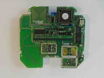
NL3EL0001
Mar 11, 2002Electric Meter
Equipment Class
DSS - Part 15 Spread Spectrum Transmitter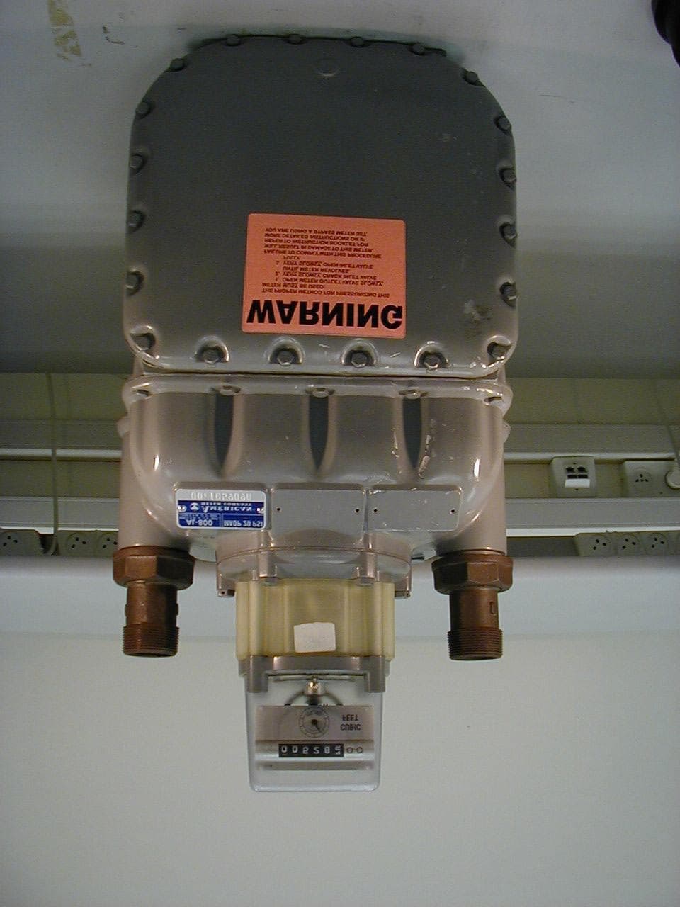
NL3GA0006
Sep 19, 2001Gas Meter
Equipment Class
DSS - Part 15 Spread Spectrum Transmitter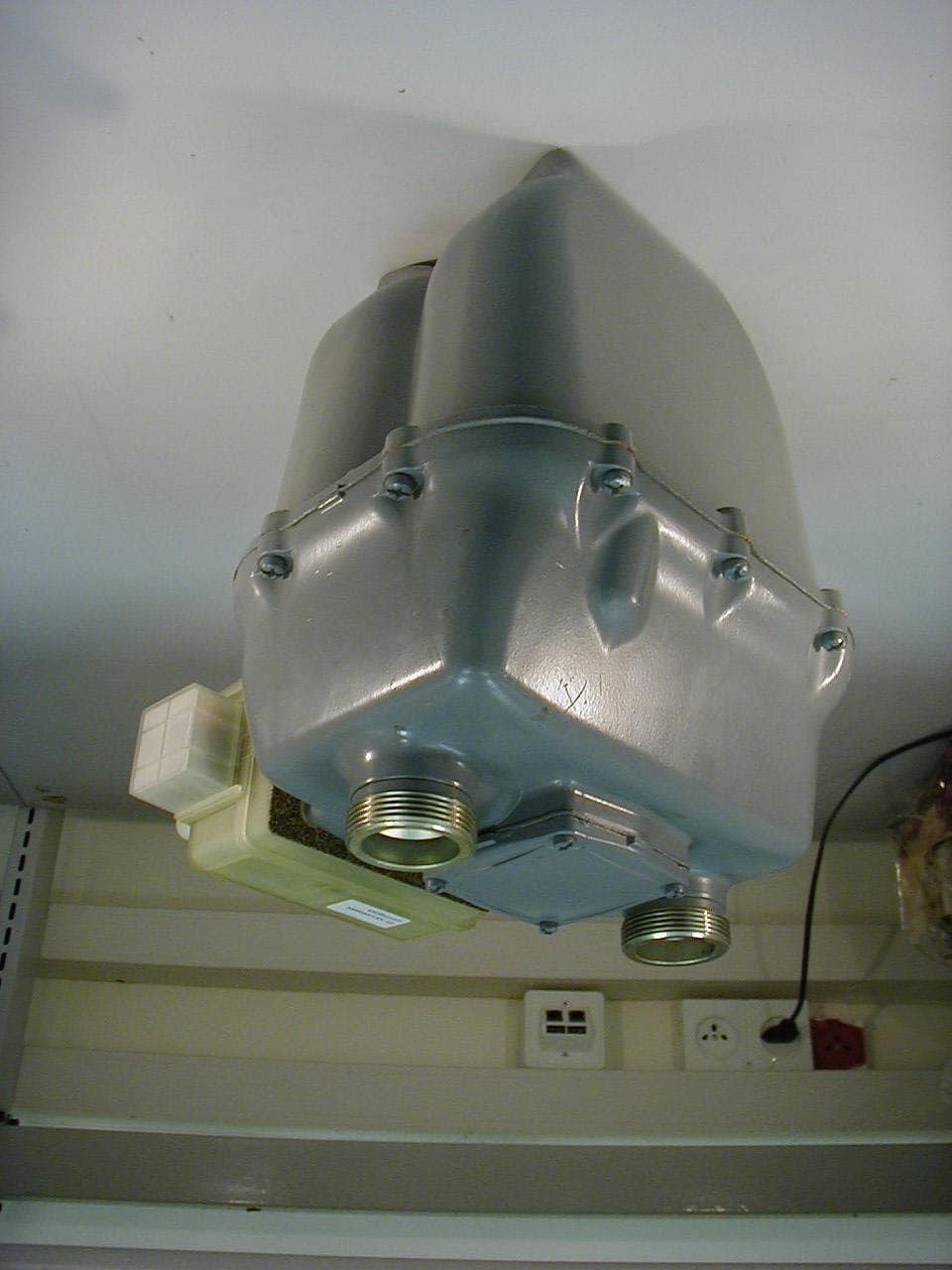
NL3GA0002
Jul 16, 2001DSS - Part 15 Spread Spectrum Transmitter
Equipment Class
DSS - Part 15 Spread Spectrum Transmitter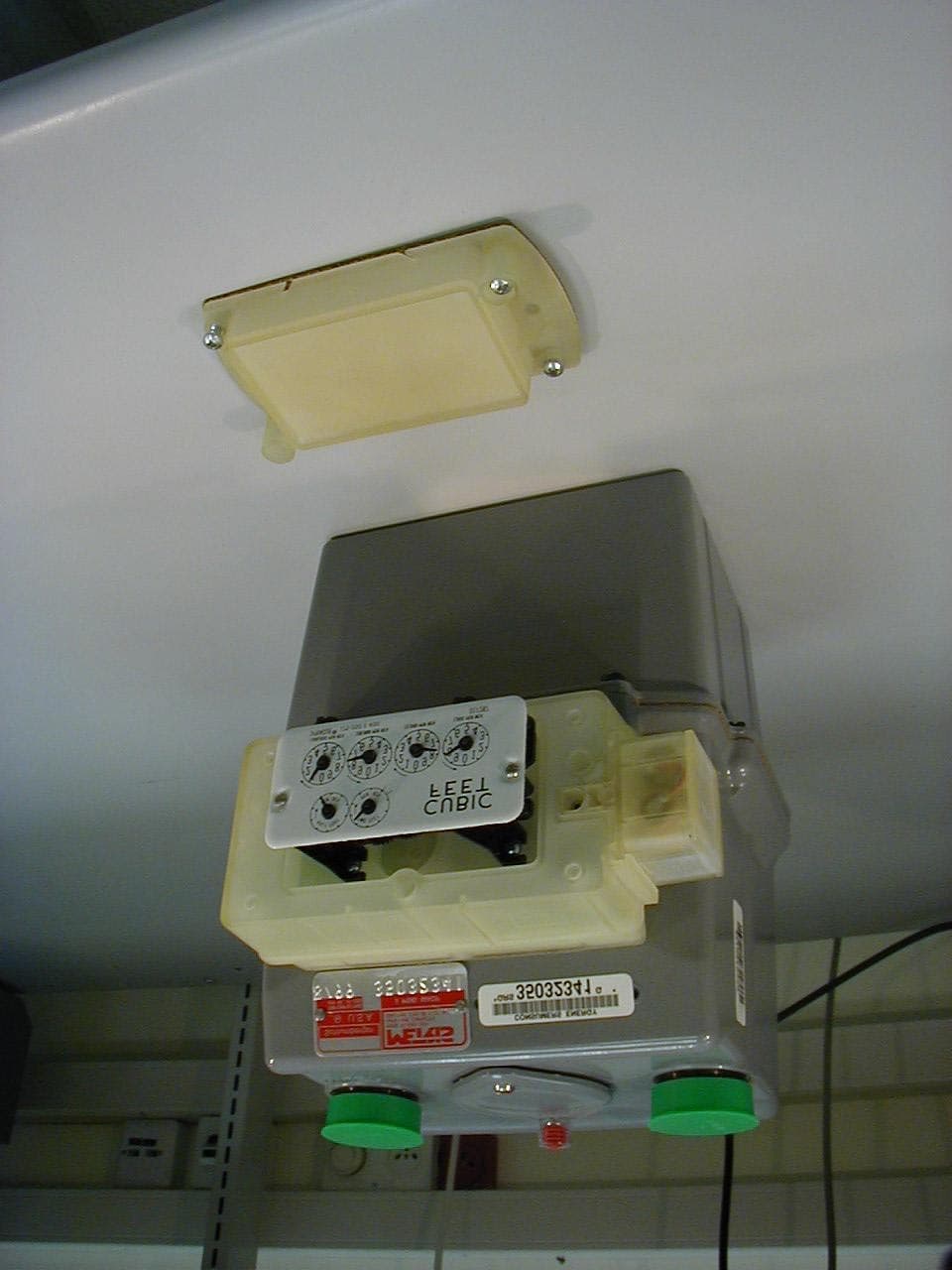
NL3GA0003
Jul 12, 2001Gas Meter
Equipment Class
DSS - Part 15 Spread Spectrum Transmitter