NL3TR0001Network Transceiver Repeater
NexusData Ltd.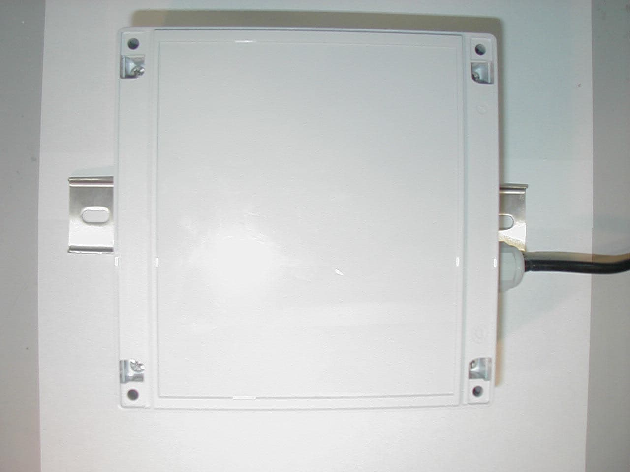
Click to zoom
Application Details
- Equipment Class
- DTS - Digital Transmission System
- Date of Grant
- Oct 07, 2002
- Application Purpose
- Original Equipment
- Date of Application
- Aug 03, 2002
- Equipment Note
- Network Transceiver Repeater
- Frequency Range
- 903.80000000 - 926.20000000
- Company
- NexusData Ltd.
- Country
- Israel
Documents & Files
Document Text
Text extracted from the exhibit documents filed with the FCC. Open a document above to read the original.
Users Manual
REV. ECO No. APPROVED NAME SIGNATURE A First release NAME SIGNATURE DATE DESCRIPTION: Product Manager R&D Manager INSTALLATION GUIDE Testing REPEATER Manufacturing Eng. Shay Aharon RX-TX QA Engineering Shay Aharon SH 1 OF DRAW No. DC00019-001 REV. A DRAW NO.: DC00019-001 DESCRIPTION: FINAL ASSEMBLY REPEATER RX-TX REV A SH. _2_ OF_13_ DRAW NO.: DC00019-001 DESCRIPTION: FINAL ASSEMBLY REPEATER RX-TX REV A SH. _3_ OF_13_ Table of Contents Mechanical Assembly Description............................4 PCB...........................................................................4 Front Box...................................................................4 Gland.........................................................................5 Assembly Pcb............................................................6 Cover Pcb..................................................................7 Label..........................................................................7 Mounting....................................................................9 AC Cable.........................................................9 Top Cover................................................................10 DRAW NO.: DC00019-001 DESCRIPTION: FINAL ASSEMBLY REPEATER RX-TX REV A SH. _4_ OF_13_ Mechanical Assembly Description FCC Warning Modifications not expressly approved by the manufacturer could void the user authority to operate the equipment under FCC Rules. In order to comply with FCC RF Exposure requirements, the AMR unit must be installed in such a way that there is a 20 c”m separation distance between it and all persons during normal operation. Front Box Attach standoffs with plain washer, nut and spring washer to the lower board. DRAW NO.: DC00019-001 DESCRIPTION: FINAL ASSEMBLY REPEATER RX-TX REV A SH. _5_ OF_13_ Attach the lower board into the front box and assemble screws. Gland Assemble gland with nut and washer. DRAW NO.: DC00019-001 DESCRIPTION: FINAL ASSEMBLY REPEATER RX-TX REV A SH. _6_ OF_13_ Assembly Pcb Assemble the Pcb into the front box and hold it with standoffs, screws, and washers. DRAW NO.: DC00019-001 DESCRIPTION: FINAL ASSEMBLY REPEATER RX-TX REV A SH. _7_ OF_13_ Cover Pcb Place the RF shield above Pcb and assemble screws and washers. Label DRAW NO.: DC00019-001 DESCRIPTION: FINAL ASSEMBLY REPEATER RX-TX REV A SH. _8_ OF_13_ Place warning label on top of the RF shield. DRAW NO.: DC00019-001 DESCRIPTION: FINAL ASSEMBLY REPEATER RX-TX REV A SH. _9_ OF_13_ Antenna Place the antenna and assemble plastic screws. Mounting Place the bracket and tighten with screws. DRAW NO.: DC00019-001 DESCRIPTION: FINAL ASSEMBLY REPEATER RX-TX REV A SH. _10_ OF_13_ AC Cable place the AC cable into the front box DRAW NO.: DC00019-001 DESCRIPTION: FINAL ASSEMBLY REPEATER RX-TX REV A SH. _11_ OF_13_ Assemble AC cable with screws Top Cover Place the top cover on the front box and assemble screws. DRAW NO.: DC00019-001 DESCRIPTION: FINAL ASSEMBLY REPEATER RX-TX REV A SH. _12_ OF_13_ Sealed the top cover with strips. Final assembly DRAW NO.: DC00019-001 DESCRIPTION: FINAL ASSEMBLY REPEATER RX-TX REV A SH. _13_ OF_13_
Users Manual
REV. ECO No. APPROVED NAME SIGNATURE A First release NAME SIGNATUREDATE DESCRIPTION: Product Manager R&D Manager INSTALLATION GUIDE Testing NTR Manufacturing Eng. Shay Versano QA Engineering Shay Versano SH 1 OF DRAW No. DC00019-001 REV. A DRAW NO.: DC00019-001 DESCRIPTION: FINAL ASSEMBLY REPEATER RX-TX REV A SH. _2_ OF_19_ Table of Contents FCC Warning................................................................................................................... 3 Mechanical Assembly..................................................................................................... 4 Front Box....................................................................................................................... 4 Gland............................................................................................................................. 5 PCB Assembly............................................................................................................... 6 PCB Cover..................................................................................................................... 7 Label.............................................................................................................................. 8 Antenna......................................................................................................................... 9 Mounting...................................................................................................................... 10 AC Cable..................................................................................................................... 11 Top Cover.................................................................................................................... 12 Final Assembly............................................................................................................ 13 Field Installation............................................................................................................ 14 General Instructions.................................................................................................... 14 Installation Steps......................................................................................................... 14 DRAW NO.: DC00019-001 DESCRIPTION: FINAL ASSEMBLY REPEATER RX-TX REV A SH. _3_ OF_19_ FCC Warning FCC Warning Modifications not expressly approved by the manufacturer could void the user authority to operate the equipment under FCC Rules. DRAW NO.: DC00019-001 DESCRIPTION: FINAL ASSEMBLY REPEATER RX-TX REV A SH. _4_ OF_19_ Mechanical Assembly Front Box Attach standoffs with plain washer, nut and spring washer to the lower board. Attach the lower board into the front box and assemble screws. DRAW NO.: DC00019-001 DESCRIPTION: FINAL ASSEMBLY REPEATER RX-TX REV A SH. _5_ OF_19_ Gland Assemble gland with nut and washer. DRAW NO.: DC00019-001 DESCRIPTION: FINAL ASSEMBLY REPEATER RX-TX REV A SH. _6_ OF_19_ PCB Assembly Assemble the PCB into the front box and hold it with standoffs, screws, and washers. DRAW NO.: DC00019-001 DESCRIPTION: FINAL ASSEMBLY REPEATER RX-TX REV A SH. _7_ OF_19_ PCB Cover Place the RF shield above PCB and assemble screws and washers. DRAW NO.: DC00019-001 DESCRIPTION: FINAL ASSEMBLY REPEATER RX-TX REV A SH. _8_ OF_19_ Label Place warning label on top of the RF shield. DRAW NO.: DC00019-001 DESCRIPTION: FINAL ASSEMBLY REPEATER RX-TX REV A SH. _9_ OF_19_ Antenna Place the antenna and assemble plastic screws. DRAW NO.: DC00019-001 DESCRIPTION: FINAL ASSEMBLY REPEATER RX-TX REV A SH. _10_ OF_19_ Mounting Place the bracket and tighten with screws. DRAW NO.: DC00019-001 DESCRIPTION: FINAL ASSEMBLY REPEATER RX-TX REV A SH. _11_ OF_19_ AC Cable place the AC cable into the front box Assemble AC cable with screws DRAW NO.: DC00019-001 DESCRIPTION: FINAL ASSEMBLY REPEATER RX-TX REV A SH. _12_ OF_19_ Top Cover Place the top cover on the front box and assemble screws. Sealed the top cover with strips. DRAW NO.: DC00019-001 DESCRIPTION: FINAL ASSEMBLY REPEATER RX-TX REV A SH. _13_ OF_19_ Final Assembly DRAW NO.: DC00019-001 DESCRIPTION: FINAL ASSEMBLY REPEATER RX-TX REV A SH. _14_ OF_19_ Field Installation General Instructions The NTR must be installed at least 3 meters above the floor. Select the installation location in where no moving/mobile nor static objects would exist or enter into within 2 meters of the NTR surrounding, excluding the wall or pipe where the NTR is installed on. Installation Steps Locate installation place, on a roof of a dominate building in the area where the NTR services are required. DRAW NO.: DC00019-001 DESCRIPTION: FINAL ASSEMBLY REPEATER RX-TX REV A SH. _15_ OF_19_ Mark 2 point for drilling. DRAW NO.: DC00019-001 DESCRIPTION: FINAL ASSEMBLY REPEATER RX-TX REV A SH. _16_ OF_19_ drill 2 holes. DRAW NO.: DC00019-001 DESCRIPTION: FINAL ASSEMBLY REPEATER RX-TX REV A SH. _17_ OF_19_ assemble screw-holders. DRAW NO.: DC00019-001 DESCRIPTION: FINAL ASSEMBLY REPEATER RX-TX REV A SH. _18_ OF_19_ Assemble 2 screws. DRAW NO.: DC00019-001 DESCRIPTION: FINAL ASSEMBLY REPEATER RX-TX REV A SH. _19_ OF_19_ NTR Final installation
Users Manual
REV.ECO No.APPROVEDNAMESIGNATURE AFirst release NAMESIGNATUREDATEDESCRIPTION: Product Manager R&D Manager INSTALLATION GUIDE Testing NTR Manufacturing Eng. Shay Versano QA Engineering Shay Versano SH 1 OFDRAW No. DC00019-001 REV. A DRAW NO .: DC00019-001 DESCRIPTION: FINAL ASSEMBLY REPEATER RX-TX REV A SH. _2_ OF_19_ Table of Contents FCC Warning.................................................................................................................... 3 Mechanical Assembly..................................................................................................... 4 Front Box .......................................................................................................................4 Gland ............................................................................................................................. 5 PCB Assembly............................................................................................................... 6 PCB Cover ..................................................................................................................... 7 Label .............................................................................................................................. 8 Antenna .........................................................................................................................9 Mounting ...................................................................................................................... 10 AC Cable ..................................................................................................................... 11 Top Cover .................................................................................................................... 12 Final Assembly ............................................................................................................ 13 Field Installation............................................................................................................ 14 General Instructions..................................................................................................... 14 Installation Steps ......................................................................................................... 14 DRAW NO .: DC00019-001 DESCRIPTION: FINAL ASSEMBLY REPEATER RX-TX REV A SH. _3_ OF_19_ FCC Warning FCC Warning Modifications not expressly approved by the manufacturer could void the user authority to operate the equipment under FCC Rules. In order to comply with FCC RF Exposure requirements, the NTR unit must be installed in such a way that there is a 2 meters separation distance between it and all persons during normal operation. The installer must maintain 2 meters separation distance from the NTR when the device is operational. DRAW NO .: DC00019-001 DESCRIPTION: FINAL ASSEMBLY REPEATER RX-TX REV A SH. _4_ OF_19_ Mechanical Assembly Front Box Attach standoffs with plain washer, nut and spring washer to the lower board. Attach the lower board into the front box and assemble screws. DRAW NO .: DC00019-001 DESCRIPTION: FINAL ASSEMBLY REPEATER RX-TX REV A SH. _5_ OF_19_ Gland Assemble gland with nut and washer. DRAW NO .: DC00019-001 DESCRIPTION: FINAL ASSEMBLY REPEATER RX-TX REV A SH. _6_ OF_19_ PCB Assembly Assemble the PCB into the front box and hold it with standoffs, screws, and washers. DRAW NO .: DC00019-001 DESCRIPTION: FINAL ASSEMBLY REPEATER RX-TX REV A SH. _7_ OF_19_ PCB Cover Place the RF shield above PCB and assemble screws and washers. DRAW NO .: DC00019-001 DESCRIPTION: FINAL ASSEMBLY REPEATER RX-TX REV A SH. _8_ OF_19_ Label Place warning label on top of the RF shield. DRAW NO .: DC00019-001 DESCRIPTION: FINAL ASSEMBLY REPEATER RX-TX REV A SH. _9_ OF_19_ Antenna Place the antenna and assemble plastic screws. DRAW NO .: DC00019-001 DESCRIPTION: FINAL ASSEMBLY REPEATER RX-TX REV A SH. _10_ OF_19_ Mounting Place the bracket and tighten with screws. DRAW NO .: DC00019-001 DESCRIPTION: FINAL ASSEMBLY REPEATER RX-TX REV A SH. _11_ OF_19_ AC Cable place the AC cable into the front box Assemble AC cable with screws DRAW NO .: DC00019-001 DESCRIPTION: FINAL ASSEMBLY REPEATER RX-TX REV A SH. _12_ OF_19_ Top Cover Place the top cover on the front box and assemble screws. Sealed the top cover with strips. DRAW NO .: DC00019-001 DESCRIPTION: FINAL ASSEMBLY REPEATER RX-TX REV A SH. _13_ OF_19_ Final Assembly DRAW NO .: DC00019-001 DESCRIPTION: FINAL ASSEMBLY REPEATER RX-TX REV A SH. _14_ OF_19_ Field Installation General Instructions The NTR must be installed at least 3 meters above the floor. Select the installation location in where no moving/mobile nor static objects would exist or enter into within 2 meters of the NTR surrounding, excluding the wall or pipe where the NTR is installed on. Installation Steps Locate installation place, on a roof of a dominate building in the area where the NTR services are required. DRAW NO .: DC00019-001 DESCRIPTION: FINAL ASSEMBLY REPEATER RX-TX REV A SH. _15_ OF_19_ Mark 2 point for drilling. DRAW NO .: DC00019-001 DESCRIPTION: FINAL ASSEMBLY REPEATER RX-TX REV A SH. _16_ OF_19_ drill 2 holes. DRAW NO .: DC00019-001 DESCRIPTION: FINAL ASSEMBLY REPEATER RX-TX REV A SH. _17_ OF_19_ assemble screw-holders. DRAW NO .: DC00019-001 DESCRIPTION: FINAL ASSEMBLY REPEATER RX-TX REV A SH. _18_ OF_19_ Assemble 2 screws . DRAW NO .: DC00019-001 DESCRIPTION: FINAL ASSEMBLY REPEATER RX-TX REV A SH. _19_ OF_19_ NTR Final installation
External Photos
Closed/Assembled Unit, External View
ID Label/Location Info
Figure 1. FCC Label Figure 2. Location of Label on EUT 40mm 15mm FCC ID: NL3TR0001 THIS DEVICE COMPLIES WITH PART 15 OF THE FCC RULES. OPERATION IS SUBJECT TO THE FOLLOWING TWO CONDITIONS: (1) THIS DEVICE MAY NOT CAUSE HARMFUL INTERFERENCE. (2) THIS DEVICE MUST ACCEPT ANY INTERFERENCE RECEIVED, INCLUDING INTERFERENCE THAT MAY CAUSE UNDESIRED OPERATION.
Internal Photos
Antenna Cover Removed Antenna Cover and Antenna Removed Antenna Unit Connector Interfacing the Antenna Printed Circuit Side 1 Printed Circuit Side 2 Printed Circuit Mounted in Housing/ E.U.T. Disassembled
RF Exposure Info
Cert. No. 1152.01 Electrical (EMC) Test Report E45900.01 Nexus Data (1993) Ltd. Page 1 of 96 FCC ACC M Ver 1.1 05Mayl 2000 DATE: 07 October 2002 I.T.L. (PRODUCT TESTING) LTD. EMC Test for Nexus Data (1993) Ltd. Equipment under test: Network Transceiver/Repeater (For Transmitter Section) P3V7-89 Approved by:_____________________________ I. Raz, EMC Laboratory Manager This report must not be reproduced, except in full, without the written permission of I.T.L. (Product Testing) Ltd. This report relates only to items tested. Cert. No. 1152.01 Electrical (EMC) Test Report E45900.01 Nexus Data (1993) Ltd. Page 2 of 96 FCC ACC M Ver 1.1 05Mayl 2000 Measurement/Technical Report for Nexus Data (1993) Ltd. Network Transceiver/Repeater (For Transmitter Section) P3V7-89 FCC ID:NL3NTR0001 07 October 2002 This report concerns:Original Grant x Class II change Class B verification Class A verification Class I change Equipment type: Radio Telemetry Transmitter Request Issue of Grant: x Immediately upon completion of review Limits used: CISPR 22 Part 15 x Measurement procedure used is ANSI C63.4-1992. Application for Certification Applicant for this device: prepared by:(different from "prepared by") Ishaishou RazShimon Zigdon ITL (Product Testing) Ltd.Nexus Data (1993) Ltd. Kfar Bin Nun16 Hamelacha St. D.N. Shimshon 99780Rosh Haayin 48091 IsraelIsrael e-mail [email protected]:+972- 903-2288 Fax:+972- 903-32299 e-mail: [email protected] Test Report E45900.01 Nexus Data (1993) Ltd. Page 93 of 96 FCC ACC M Ver 1.1 05Mayl 2000 16. R.F Exposure/Safety The E.U.T. is installed in fixed locations for application of transmitting data of gas consumption to central data collection offices. The distance between the E.U.T. and the general population is at least two meters. Calculation of Maximum Permissible Exposure (MPE) Based on Section 1.1307(b)(1); 1.1310 Requirements for General Population/ Uncontrolled Exposures. (a) FCC limits at 903.8 MHz (b) The power density produced by the E.U.T. is P t - Transmitted Power 1000mw (Peak) G T - Antenna Gain, 2(3dBi) R- Distance from Transmitter using 1m worst case (c) The peak power density is : (d) This level is significantly below the FCC limit. 2 6.0 1500 8.903 cm mW S == 2 4R GP S tt π = 22 3 016.0 )100(4 210 cm mWx S p == π
Test Report
Cert. No. 1152.01 Electrical (EMC) Test Report E45900.00 Nexus Data (1993) Ltd. Page 1 of 96 FCC ACC M Ver 1.1 05Mayl 2000 DATE: 08 July 2002 I.T.L. (PRODUCT TESTING) LTD. EMC Test for Nexus Data (1993) Ltd. Equipment under test: Network Transceiver/Repeater (For Transmitter Section) P3V7-89 Approved by: _____________________________ I. Raz, EMC Laboratory Manager This report must not be reproduced, except in full, without the written permission of I.T.L. (Product Testing) Ltd. This report relates only to items tested. Cert. No. 1152.01 Electrical (EMC) Test Report E45900.00 Nexus Data (1993) Ltd. Page 2 of 96 FCC ACC M Ver 1.1 05Mayl 2000 Measurement/Technical Report for Nexus Data (1993) Ltd. Network Transceiver/Repeater (For Transmitter Section) P3V7-89 FCC ID:NL3TR0001 08 July 2002 This report concerns: Original Grant x Class II change Class B verification Class A verification Class I change Equipment type: Radio Telemetry Transmitter Request Issue of Grant: x Immediately upon completion of review Limits used: CISPR 22 Part 15 x Measurement procedure used is ANSI C63.4-2000. Application for Certification Applicant for this device: prepared by: (different from "prepared by") Ishaishou Raz Shimon Zigdon ITL (Product Testing) Ltd. Nexus Data (1993) Ltd. Kfar Bin Nun 16 Hamelacha St. D.N. Shimshon 99780 Rosh Haayin 48091 Israel Israel e-mail [email protected] Tel: +972- 903-2288 Fax: +972- 903-32299 e-mail: [email protected] Test Report E45900.00 Nexus Data (1993) Ltd. Page 3 of 96 FCC ACC M Ver 1.1 05Mayl 2000 TABLE OF CONTENTS 1. GENERAL INFORMATION------------------------------------------------------------------------------------------6 1.1 Administrative Information...........................................................................6 1.2 List of Accreditations..................................................................................7 1.3 Product Description....................................................................................8 1.4 Test Methodology.......................................................................................9 1.5 Test Facility...............................................................................................9 1.6 Measurement Uncertainty...........................................................................9 2. PRODUCT LABELING-----------------------------------------------------------------------------------------------10 3. SYSTEM TEST CONFIGURATION------------------------------------------------------------------------------11 3.1 Justification..............................................................................................11 3.2 EUT Exercise Software..............................................................................11 3.3 Special Accessories..................................................................................11 3.4 Equipment Modifications............................................................................11 3.5 Configuration of Tested System..................................................................12 4. BLOCK DIAGRAM-----------------------------------------------------------------------------------------------------13 4.1 Schematic Block/Connection Diagram........................................................13 4.2 Theory of Operation...................................................................................14 5. CONDUCTED AND RADIATED MEASUREMENT PHOTOS------------------------------------------15 6. CONDUCTED EMISSION-------------------------------------------------------------------------------------------17 6.1 Test Specification......................................................................................17 6.2 Test Procedure.........................................................................................17 6.3 Measured Data.........................................................................................18 6.4 Test Instrumentation Used, Conducted Measurement...................................23 7. RADIATED EMISSION, BELOW 1 GHZ-----------------------------------------------------------------------24 7.1 Test Specification......................................................................................24 7.2 Test Procedure.........................................................................................24 7.3 Measured Data.........................................................................................25 7.4 Test Instrumentation Used, Radiated Measurements....................................38 7.5 Field Strength Calculation..........................................................................39 8. RADIATED EMISSION ABOVE 1 GHZ-------------------------------------------------------------------------40 1.1 Radiated Emission Above 1 GHz................................................................40 8.2 Test Data.................................................................................................40 8.3 Test Instrumentation Used, Radiated Measurements Above 1 GHz................66 9. MAXIMUM TRANSMITTED PEAK POWER OUTPUT---------------------------------------------------67 9.1 Test procedure..........................................................................................67 9.2 Results table............................................................................................69 9.3 Test Equipment Used................................................................................70 10. PEAK POWER OUTPUT OUT OF 902-928 MHZ BAND-------------------------------------------------71 10.1 Test procedure..........................................................................................71 10.2 Results table............................................................................................73 10.3 Test Equipment Used................................................................................74 11. 6 DB MINIMUM BANDWIDTH---------------------------------------------…
Text truncated - open the document above for the full version.
Test Setup Photos
Figure 1. Conducted Emission Test. Front Figure 2. Conducted Emission Test. Side Figure 3. Radiated Emission Test. Front Figure 4. Radiated Emission Test. Side
Contact Information
Applicant
Shimon Zigdon(Hardware Manager)
Technical Contact
Israel Testing LaboratoriesShaike Raz
[email protected]972-8-9797799
26 Hacharoshet St. · Or-Yehuda · Israel
Non-Technical Contact
NexusData Ltd.Shimon Zigdon
[email protected]972-3-9032288
Test Firm
Israel Testing LaboratoriesIIan Cohen
Technical Specifications
| # | Rule Parts | Frequency Range | Power Output |
|---|---|---|---|
| 1 | 15C | 903.8 MHz - 926.2 MHz | 900.00 mW |
Other Applications from NexusData Ltd.
NL3EL0001
Mar 11, 2002Electric Meter
Equipment Class
DSS - Part 15 Spread Spectrum Transmitter
NL3GA0006
Sep 19, 2001Gas Meter
Equipment Class
DSS - Part 15 Spread Spectrum Transmitter
NL3GA0002
Jul 16, 2001DSS - Part 15 Spread Spectrum Transmitter
Equipment Class
DSS - Part 15 Spread Spectrum Transmitter
NL3GA0003
Jul 12, 2001Gas Meter
Equipment Class
DSS - Part 15 Spread Spectrum Transmitter
NL3GA0005
Feb 28, 2001DSSS Gas Meter Transmitter
Equipment Class
DSS - Part 15 Spread Spectrum Transmitter