NLMSWLQ93TWiFi Module
Hanwha Techwin Co., Ltd.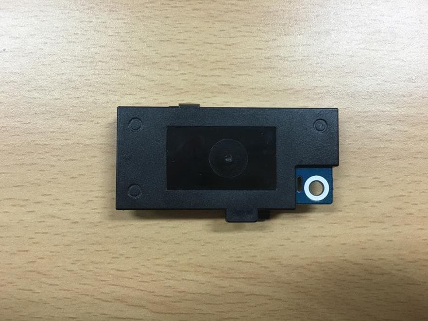
Click to zoom
Application Details
- Equipment Class
- NII - Unlicensed National Information Infrastructure TX
- Date of Grant
- Dec 22, 2015
- Application Purpose
- Original Equipment
- Date of Application
- Dec 21, 2015
- Equipment Note
- WiFi Module
- Frequency Range
- 5500.00000000 - 5700.00000000
- Company
- Hanwha Techwin Co., Ltd.
- Country
- South Korea
Documents & Files
Document Text
Text extracted from the exhibit documents filed with the FCC. Open a document above to read the original.
Users Manual
User manual of SWL-Q93T 1. Introduction SWL-Q93T is a USB embedded module compliant with IEEE802.11n standard. The core chipset is from Qualcomm, part number is AR9374X. 2. Hardware Architecture: 2.1 Main Chipset Information Item Vender Part number MAC/BBP/Radio Transceiver/PA Qualcomm AR9374X 3.3 Antennas Information Two SMD antennas supporting both TX & RX. 4. Operational Description SWL-Q93T is the 802.11a/b/g/n RF Module, that acts as a communication hub for users of a wireless device to connect to a wired LAN. MIMO type Product type: WLAN (11b mode: 1TX, 1RX, 11g mode: 1TX, 1RX, Draft n mode: 2TX, 2RX) Time base of the transmission frequency For IF and RF frequency, Crystal is a clock reference. Synthesizer Synthesizer inside Transceiver. Internal voltage controlled oscillator (VCO) provides the desired LO signal base on the phase-locked loop (PLL) with a relatively wide tuning range for this application. Transmission Base-band Processing (BBP) IC has DSSS (BPSK/QPSK/CCK) and OFDM (BPSK/QPSK/16QAM/64QAM) modulation function, it provides transmission data rate are 1, 2, 5.5, 11 Mbps on DSSS and 6, 12, 18, 24, 36, 48, 54 Mbps on OFDM. Digital data signal will be converted to analog (TX IQ) signals through DAC in BBP IC, TX IQ pass through to low pass filter. TX I/Q signal use direct conversion (zero-IF) architecture converter to generate carrier frequency signal. Transceiver IC and internal PA magnify output power. Receiver Reverse direction isolation of LNA inside Transceiver IC suppresses unwanted radiation. Then RF signal will be directly down to IF signal (RX IQ) and high frequency spurious emissions are suppressed by LPF. At last RX IQ signal will be demodulated digital data. Base band Processing 1. Channel selection is controlled by BBP IC to support data modulation: - DSSS (BPSK/QPSK/CCK) - OFDM (BPSK/QPSK/16QAM/64QAM) Power Control Level It uses closed-loop power control function to limit RF output power level. Transmit/Receive Switch EUT has Transmit/Receive Switch and Antenna switch. End user can’t select any power setting. Channel Selection Restriction For product available in the USA/Canada/Taiwan market, only channel 1~11 can be operated. Selection of other channels is not possible. But product also could be available in the Europe/Japan market, channel 1~13 can be operated under the manufacturer change the different driver. Data Rate Control The operation date rate is changing during data transfer base on the optimization of driver. Discontinue Transmitting with absence of Data or operational failure states “The device shall automatically discontinue transmission in case of either absence of information to transmit or operational failure. These provisions are not intended to preclude the transmission of control or signaling information or the use of repetitive codes used by certain digital technologies to complete frame or burst intervals. Applicants shall include in their application for equipment authorization a description of how this requirement is met.” Data transmission is always initiated by software, which is then passed down through the MAC, through the digital and analog baseband, and finally to the RF chip. Several special packets (ACKs, CTS, PSPoll, etc...) are initiated by the MAC. These are the only ways the digital baseband portion will turn on the RF transmitter, which it then turns off at the end of the packet. Therefore, the transmitter will be on only while one of the aforementioned packets is being transmitted. Product Details > Modulation see the below table for draft n > Data Modulation OFDM (BPSK / QPSK / 16QAM / 64QAM) > Frequency : 2.4GHz and 5GHz > Data Rate (Mbps) see the below table for Draft n > Channel Number 4 for 20MHz bandwidth ; 2 for 40MHz bandwidth > Channel Band Width (99%) MCS8 (20MHz): 18.08 MHz ; MCS8 (40MHz): 36.48 MHz Modulation modes 5. Notice FCC Statement Federal Communication Commission Interference Statement This equipment has been tested and found to comply with the limits for a Class B digital device, pursuant to Part 15 of the FCC Rules. These limits are designed to provide reasonable protection against harmful interference in a residential installation. This equipment generates, uses and can radiate radio frequency energy and, if not installed and used in accordance with the instructions, may cause harmful interference to radio communications. However, there is no guarantee that interference will not occur in a particular installation. If this equipment does cause harmful interference to radio or television reception, which can be determined by turning the equipment off and on, the user is encouraged to try to correct the interference by one of the following measures: ● Reorient or relocate the receiving antenna. ● Increase the separation between the equipment and receiver. ● Connect the equipment into an outlet on a circuit different from that to which the receiver is connected. ● Consult the dealer or an experienced radio/TV technician for help. FCC Caution: Any changes or modifications not expressly approved by the party responsible for compliance could void the user’s authority to operate this equipment. This device complies with Part 15 of the FCC Rules. Operation is subject to the following two conditions: (1) This device may not cause harmful interference, and (2) this device must accept any interference received, including interference that may cause undesired operation. For product available in the USA/Canada market, only channel 1~11 can be operated and these channel assignments deal with only the 2.4 GHz range. This device and its antenna(s) must not be co-located or operation in conjunction with any other antenna or transmitter. This device is going to be operated in 5.15~5.25GHz frequency range, it is restricted in indoor environment only. IMPORTANT NOTE: FCC Radiation Exposure Statement: This equipment complies with FCC radiation exposure limits set forth for an uncontrolled environment. This equipment shou…
Text truncated - open the document above for the full version.
Cover Letter(s)
1204, Changwon-daero, Seongsan-gu Changwon-si Gyeongsangnam-do, South Korea T. 82-70-7147-8361 F. 82-31-8108-3717 Date: December 17, 2015 Federal Communications Commission 7435 Oakland Mills Road Columbia MD 21046 To whom it may concern: I, the undersigned, hereby authorize Jeff Do of KES Co., Ltd. and hereafter referred to as KES Co., Ltd., to act on our behalf in all manners relating to application for equipment authorization, including signing of all documents relating to these matters. Any and all acts carried out by KT Kang of KES Co., Ltd. on our behalf shall have the same effect as acts of our own. I, the undersigned, hereby certify that we are not subject to a denial of federal benefits, that includes FCC benefits, pursuant to Section 5301 of the Anti-Drug Abuse Act of 1988, 21 U.S.C. 853(a). In authorizing KES Co., Ltd. as our agent, we still recognize that we are responsible to: a) comply with the relevant provisions of the certification program; b) make all necessary arrangements for the conduct of the evaluation, including provision for examining documentation and access to all areas, records (including internal audit reports) and personnel for the purposes of evaluation (e.g. testing, inspection, assessment, surveillance, reassessment) and resolution of complaints; c) make claims regarding certification only in respect of the scope for which certification has been granted; d) do not use our product certification in such a manner as to bring the Certification Division into disrepute and not make any statement regarding our product certification which the Certification Division may consider misleading or unauthorized; 1204, Changwon-daero, Seongsan-gu Changwon-si Gyeongsangnam-do, South Korea T. 82-70-7147-8361 F. 82-31-8108-3717 e) upon suspension or cancellation of certification, discontinue use of all advertising matter that contains any reference thereto and return any certification documents as required by the Certification Division; f) use certification only to indicate the products are certified as being in conformity with specified standards; g) endeavor to ensure that no certificate or report nor any part thereof is used in a misleading manner; h) ensure that any reference to our product certification in communication media such as documents, brochures or advertising, complies with the requirements of the Certification Division; i) keep a record of all complaints made known to the us relating to the product’s compliance with requirements of the relevant standard and to make these records available to the Certification Division when requested; j) take appropriate action with respect to such complaints and any deficiencies found in products or services that affect compliance with the requirements for certification; k) document the actions taken. This authorization is valid until further written notice from the applicant. Sincerely Yours, Jeisoon Kang Principal Research Engineer Hanwha Techwin Co., Ltd.
Cover Letter(s)
1204, Changwon-daero, Seongsan-gu Changwon-si Gyeongsangnam-do, South Korea T. 82-70-7147-8361 F. 82-31-8108-3717 Date: December 17, 2015 Federal Communications Commission Authorization and Evaluation Division Confidentiality Request regarding application for certification of FCC ID: NLMSWLQ93T Pursuant to Sections 0.457 and 0.459 of the Commission’s Rules, we hereby request confidential treatment of information accompanying this application as outlined below: Exhibit Type File Name Part List CONF APPENDIX_Part List_SWL-Q93T.PDF Schematics Diagram(s) CONF APPENDIX_Schematics_SWL-Q93T.PDF Block diagram CONF APPENDIX_Block diagram_SWL-Q93T.PDF Operation description CONF APPENDIX_Operation description_SWL-Q93T.PDF The above materials contain trade secrets and proprietary information not customarily released to the public. The public disclosure of these materials may be harmful to the applicant and provide unjustified benefits to its competitors. The applicant understands that pursuant to Section 0.457 of the Rules, disclosure of this application and all accompanying documentation will not be made before the date of the Grant for this application. Sincerely, Jeisoon Kang Principal Research Engineer Hanwha Techwin Co., Ltd.
Cover Letter(s)
1204, Changwon-daero, Seongsan-gu Changwon-si Gyeongsangnam-do, South Korea T. 82-70-7147-8361 F. 82-31-8108-3717 Date: December 17, 2015 Federal Communications Commission Authorization and Evaluation Division Confidentiality Request regarding application for certification of FCC ID: NLMSWLQ93T Pursuant to Sections 0.457 and 0.459 of the Commission’s Rules, we hereby request confidential treatment of information accompanying this application as outlined below: Exhibit Type File Name Part List CONF APPENDIX_Part List_SWL-Q93T.PDF Schematics Diagram(s) CONF APPENDIX_Schematics_SWL-Q93T.PDF Block diagram CONF APPENDIX_Block diagram_SWL-Q93T.PDF Operation description CONF APPENDIX_Operation description_SWL-Q93T.PDF The above materials contain trade secrets and proprietary information not customarily released to the public. The public disclosure of these materials may be harmful to the applicant and provide unjustified benefits to its competitors. The applicant understands that pursuant to Section 0.457 of the Rules, disclosure of this application and all accompanying documentation will not be made before the date of the Grant for this application. Sincerely, Jeisoon Kang Principal Research Engineer Hanwha Techwin Co., Ltd.
Cover Letter(s)
Applicant / Grantee Hanwha Techwin Co., Ltd. FCC ID NLMSWLQ93T Section 15.212 Modular Transmitters Request for Modular Approval Request for Limited Modular Approval Requirements EUT Conditions Comply (Y/N) Single Modular Approval Requirements 1 The radio elements of the modular transmitter must have their own shielding. The physical crystal and tuning capacitors may be located external to the shielded radio elements. The device is equipped with Metal shielding to cover RF section. Refer to the external photos Y 2 The modular transmitter must have buffered modulation/data inputs (if such inputs are provided) to ensure that the module will comply with Part 15 requirements under conditions of excessive data rates or over- modulation. All inputs to the modules are buffered through logic or microprocessor inputs. Y 3 The modular transmitter must have its own power supply regulation.. Power supply regulation built into module. Refer to the circuit diagram. Y 4 The modular transmitter must comply with the antenna and transmission system requirements of Sections 15.203, 15.204(b) and 15.204(c). The antenna must either be permanently attached or employ a “unique” antenna coupler (at all connections between the module and the antenna, including the cable). The “professional installation” provision of Section 15.203 is not applicable to modules but can apply to limited modular approvals under paragraph (b) of this section. Connector is unique. Y 5 The modular transmitter must be tested in a stand-alone configuration, i.e., the module must not be inside another device during testing for compliance with Part 15 requirements. Unless the transmitter module will be battery powered, it must comply with the AC line conducted requirements found in Section 15.207. AC or DC power lines and data input/output lines connected to the module must not contain ferrites, unless they will be marketed with the module (see Section 15.27(a)). The length of these lines shall be the length typical of actual use or, if that length is unknown, at least 10 centimeters Refer to the test report and setup photo. Y to insure that there is no coupling between the case of the module and supporting equipment. Any accessories, peripherals, or support equipment connected to the module during testing shall be unmodified and commercially available (see Section 15.31(i)). 6 The modular transmitter must be equipped with either a permanently affixed label or must be capable of electronically displaying its FCC identification number. (A) If using a permanently affixed label, the modular transmitter must be labeled with its own FCC identification number, and, if the FCC identification number is not visible when the module is installed inside another device, then the outside of the device into which the module is installed must also display a label referring to the enclosed module. This exterior label can use wording such as the following: “Contains Transmitter Module FCC ID: XYZMODEL1” or “Contains FCC ID: XYZMODEL1.” Any similar wording that expresses the same meaning may be used. The Grantee may either provide such a label, an example of which must be included in the application for equipment authorization, or, must provide adequate instructions along with the module which explain this requirement. In the latter case, a copy of these instructions must be included in the application for equipment authorization. (B) If the modular transmitter uses an electronic display of the FCC identification number, the information must be readily accessible and visible on the modular transmitter or on the device in which it is installed. If the module is installed inside another device, then the outside of the device into which the module is installed must display a label referring to the enclosed module. This exterior label can use wording such as the following: “Contains FCC certified transmitter module(s).” Any similar wording that expresses the same meaning may be used. The user manual must include instructions on how to access the electronic display. A copy of these instructions must be included Label is to be placed on front of the EUT, and other label is to be placed in the User Manual. Refer to the FCC ID label format. Y in the application for equipment authorization. 7 The modular transmitter must comply with any specific rules or operating requirements that ordinarily apply to a complete transmitter and the manufacturer must provide adequate instructions along with the module to explain any such requirements. A copy of these instructions must be included in the application for equipment authorization. Refer to the User manual Y 8 The modular transmitter must comply with any applicable RF exposure requirements in its final configuration. It complies with RF exposure requirement. Y Jeisoon Kang Principal Research Engineer Hanwha Techwin Co., Ltd.
External Photos
External photos FCC ID.: NLMSWLQ93T Page 1 of 4 External photos FCC ID.: NLMSWLQ93T Page 2 of 4 External photos FCC ID.: NLMSWLQ93T Page 3 of 4 External photos FCC ID.: NLMSWLQ93T Page 4 of 4
ID Label/Location Info
Label and Location FCC ID.: NLMSWLQ93T Page 1 of 1 Because the device is so small that it is not practicable to place the statement specified under 15.19 statement request, the information required by this paragraph shall be placed in a prominent location in the User’s Manual.
Internal Photos
Internal photos FCC ID.: NLMSWLQ93T Page 1 of 2 Antenna 0 Antenna 1 Internal photos FCC ID.: NLMSWLQ93T Page 2 of 2
RF Exposure Info
RF Exposure FCC ID.: NLMSWLQ93T Page 1 of 2 According to FCC part 1.1310 : The criteria listed in the following table shall be used to evaluate the environment impact of human exposure to radio frequency (RF) radiation as specified in § 1.1307(b) Limits for Maximum Permissible Exposure (MPE) f= frequency in ㎒ Friis transmission formula: Pd = (Pout×G)/(4×pi×R 2 ) Where, Pd = power density in ㎽/㎠ Pout = output power to antenna in ㎽ G = gain of antenna in linear scale Pi = 3.1416 R = distance between observation point and center of the radiator in cm Pd the limit of MPE, f/1500 ㎽/㎠. If we know the maximum gain of the antenna and the total power input to the antenna, through the calculation, we will know the distance where the MPE limit is reached. Frequency range (㎒) Electric field strength(V/m) Magnetic field strength (A/m) Power density (㎽/㎠) Average time (A) Limits for Occupational / Control Exposures 300 – 1 500 -- -- f/300 6 1 500 - 100000 -- -- 5 6 (B) Limits for General Population / Uncontrol Exposures 300 – 1 500 -- -- f/1500 6 1 500 – 100 000 -- -- 1 30 RF Exposure FCC ID.: NLMSWLQ93T Page 2 of 2 Results (Worst case) Operation mode / Data Rate Frequency (㎒) Peak output power (㏈m) Antenna gain (㏈i) Power density at 20 ㎝(㎽/ ㎠) Limit (㎽/㎠) 802.11n_HT20 // 8Mbps 2 412 15.89 0.56 0.008 78 1 802.11n_HT20 // 8Mbps 2 437 15.52 0.56 0.008 07 1 802.11n_HT20 // 8Mbps 2 462 15.30 0.56 0.007 67 1 802.11n_HT40 // MCS8 5 755 19.95 3.22 0.041 28 1 802.11n_HT40 // MCS8 5 795 19.83 3.22 0.040 15 1 802.11n_HT20 // MCS8 5 180 22.38 4.82 0.104 41 1 802.11n_HT20 // MCS8 5 220 22.18 4.82 0.099 71 1 802.11n_HT20 // MCS8 5 240 22.23 4.82 0.100 86 1 802.11n_HT20 // MCS8 5 260 22.13 3.38 0.070 75 1 802.11n_HT20 // MCS8 5 300 21.76 3.38 0.064 97 1 802.11n_HT20 // MCS8 5 320 21.57 3.38 0.062 19 1 802.11n_HT20 // MCS8 5 500 20.38 3.81 0.052 21 1 802.11n_HT20 // MCS8 5 580 21.27 3.81 0.064 08 1 802.11n_HT20 // MCS8 5 700 22.25 3.81 0.080 30 1
Test Report
KES Co., Ltd. C-3701, Simin-daero 365-40, Dongan-gu, Anyang-si, Gyeonggi-do, 14057, Korea Tel: +82-31-425-6200 / Fax: +82-31-424-0450 www.kes.co.kr Test report No.: KES-RF-15T0095 Page (2 ) of (20) This report shall not be reproduced except in full, without the written approval of KES Co., Ltd. The test results in the report only apply to the tested sample. KES-P-5101-14 Rev. 1 KES A4 Revision history Revision Date of issue Test report No. Description - 2015.12.17 KES-RF-15T0095Initial KES Co., Ltd. C-3701, Simin-daero 365-40, Dongan-gu, Anyang-si, Gyeonggi-do, 14057, Korea Tel: +82-31-425-6200 / Fax: +82-31-424-0450 www.kes.co.kr Test report No.: KES-RF-15T0095 Page (3 ) of (20) This report shall not be reproduced except in full, without the written approval of KES Co., Ltd. The test results in the report only apply to the tested sample. KES-P-5101-14 Rev. 1 KES A4 TABLE OF CONTENTS 1. General information ................................................................................................................................................... 4 1.1. EUT description ................................................................................................................................................ 4 1.2. Frequency/channel operations ........................................................................................................................... 5 1.3 Information about derivative model .................................................................................................................. 5 2. Description of dynamic frequency selection test ........................................................................................................ 6 2.1 Applicability ...................................................................................................................................................... 6 2.2 Requirements ..................................................................................................................................................... 7 2.3 DFS Detection Thresholds ................................................................................................................................. 8 2.4 Parameters of DFS Test Signals ......................................................................................................................... 9 3. Summary of tests ...................................................................................................................................................... 10 4. DFS (Dynamic Frequency Selection) ....................................................................................................................... 11 4.1 Test results ..................................................................................................................................................... 12 4.1.1 Traffic load .............................................................................................................................................. 12 4.1.2 Channel Loading ..................................................................................................................................... 14 4.1.3 Channel move time & aggregate channel closing transmission time ...................................................... 16 4.1.4 Non-occupancy period ............................................................................................................................ 18 Appendix A. Measurement equipment ......................................................................................................................... 20 KES Co., Ltd. C-3701, Simin-daero 365-40, Dongan-gu, Anyang-si, Gyeonggi-do, 14057, Korea Tel: +82-31-425-6200 / Fax: +82-31-424-0450 www.kes.co.kr Test report No.: KES-RF-15T0095 Page (4 ) of (20) This report shall not be reproduced except in full, without the written approval of KES Co., Ltd. The test results in the report only apply to the tested sample. KES-P-5101-14 Rev. 1 KES A4 1. General information Applicant: Hanwha Techwin Co., Ltd. Applicant address: 1204, Changwon-daero, Seongsan-gu, Changwon-si Gyeongsangnam-do, South Korea Test site: KES Co., Ltd. Test site address: C-3701, Simin-daero 365-40, Dongan-gu, Anyang-si, Gyeonggi-do,14057, Korea 473-29, Gayeo-ro, Yeoju-si, Gyeonggi-do, 12658, Korea Rule part(s): 15.407 Test device serial No.: Production Pre-production Engineering Application purpose: Original grant Class I permissive change Class II permissive change 1.1. EUT description Equipment under test WiFi Module Frequency range 5 260 ㎒ ~ 5 320 ㎒(802.11a/n_HT20), 5 270 ㎒ ~ 5 310 ㎒(802.11n_HT40) 5 500 ㎒ ~ 5 700 ㎒(802.11a/n_HT20), 5 510 ㎒ ~ 5 670 ㎒(802.11n_HT40) Model: SWL-Q93T(Basic), SWL-CQ93(Derivative model) Modulation technique DSSS, OFDM Number of channels 5 260 ㎒ ~ 5 320 ㎒(802.11a/n_HT20) : 4ch 5 270 ㎒ ~ 5 310 ㎒(802.11n_HT40) : 2ch 5 500 ㎒ ~ 5 700 ㎒(802.11a/n_HT20) : 11ch 5 510 ㎒ ~ 5 670 ㎒(802.11n_HT40) : 5ch Antenna specification Antenna type: FIPA Antenna Power source DC 5 V KES Co., Ltd. C-3701, Simin-daero 365-40, Dongan-gu, Anyang-si, Gyeonggi-do, 14057, Korea Tel: +82-31-425-6200 / Fax: +82-31-424-0450 www.kes.co.kr Test report No.: KES-RF-15T0095 Page (5 ) of (20) This report shall not be reproduced except in full, without the written approval of KES Co., Ltd. The test results in the report only apply to the tested sample. KES-P-5101-14 Rev. 1 KES A4 1.2. Frequency/channel operations Band2A Band2C 1.3 Information about derivative model This is to notify that SWL-CQ93 are same Hardware, Software and components. Ch. Frequency (㎒) Mode 52 5 260 11a/n_HT20 . . . . . . 60 5 300 11a/n_HT20 . . . . . . 64 5 320 11a/n_HT20 Ch. Frequency (㎒) Mode 54 5 270 11n_HT40 . . . . . . 62 5 310 11n_HT40 Ch. Frequency (㎒) Mode 100 5 500 11a/n_HT20 . . . . . . 116 5 580 11a/n_HT20 . . . . . . 140 5 700 11a/n_HT20 Ch. Frequency (㎒) Mode 102 5 510 11n_HT40 . . . . . . 110 5 550 11n_HT40 . . . . . . 134 5 670 11n_…
Text truncated - open the document above for the full version.
Test Report
KES Co., Ltd. C-3701, Simin-daero 365-40, Dongan-gu, Anyang-si, Gyeonggi-do, 14057, Korea Tel: +82-31-425-6200 / Fax: +82-31-424-0450 www.kes.co.kr Test report No.: KES-RF-15T0095 Page (2 ) of (20) This report shall not be reproduced except in full, without the written approval of KES Co., Ltd. The test results in the report only apply to the tested sample. KES-P-5101-14 Rev. 1 KES A4 Revision history Revision Date of issue Test report No. Description - 2015.12.17 KES-RF-15T0095Initial KES Co., Ltd. C-3701, Simin-daero 365-40, Dongan-gu, Anyang-si, Gyeonggi-do, 14057, Korea Tel: +82-31-425-6200 / Fax: +82-31-424-0450 www.kes.co.kr Test report No.: KES-RF-15T0095 Page (3 ) of (20) This report shall not be reproduced except in full, without the written approval of KES Co., Ltd. The test results in the report only apply to the tested sample. KES-P-5101-14 Rev. 1 KES A4 TABLE OF CONTENTS 1. General information ................................................................................................................................................... 4 1.1. EUT description ................................................................................................................................................ 4 1.2. Frequency/channel operations ........................................................................................................................... 5 1.3 Information about derivative model .................................................................................................................. 5 2. Description of dynamic frequency selection test ........................................................................................................ 6 2.1 Applicability ...................................................................................................................................................... 6 2.2 Requirements ..................................................................................................................................................... 7 2.3 DFS Detection Thresholds ................................................................................................................................. 8 2.4 Parameters of DFS Test Signals ......................................................................................................................... 9 3. Summary of tests ...................................................................................................................................................... 10 4. DFS (Dynamic Frequency Selection) ....................................................................................................................... 11 4.1 Test results ..................................................................................................................................................... 12 4.1.1 Traffic load .............................................................................................................................................. 12 4.1.2 Channel Loading ..................................................................................................................................... 14 4.1.3 Channel move time & aggregate channel closing transmission time ...................................................... 16 4.1.4 Non-occupancy period ............................................................................................................................ 18 Appendix A. Measurement equipment ......................................................................................................................... 20 KES Co., Ltd. C-3701, Simin-daero 365-40, Dongan-gu, Anyang-si, Gyeonggi-do, 14057, Korea Tel: +82-31-425-6200 / Fax: +82-31-424-0450 www.kes.co.kr Test report No.: KES-RF-15T0095 Page (4 ) of (20) This report shall not be reproduced except in full, without the written approval of KES Co., Ltd. The test results in the report only apply to the tested sample. KES-P-5101-14 Rev. 1 KES A4 1. General information Applicant: Hanwha Techwin Co., Ltd. Applicant address: 1204, Changwon-daero, Seongsan-gu, Changwon-si Gyeongsangnam-do, South Korea Test site: KES Co., Ltd. Test site address: C-3701, Simin-daero 365-40, Dongan-gu, Anyang-si, Gyeonggi-do,14057, Korea 473-29, Gayeo-ro, Yeoju-si, Gyeonggi-do, 12658, Korea Rule part(s): 15.407 Test device serial No.: Production Pre-production Engineering Application purpose: Original grant Class I permissive change Class II permissive change 1.1. EUT description Equipment under test WiFi Module Frequency range 5 260 ㎒ ~ 5 320 ㎒(802.11a/n_HT20), 5 270 ㎒ ~ 5 310 ㎒(802.11n_HT40) 5 500 ㎒ ~ 5 700 ㎒(802.11a/n_HT20), 5 510 ㎒ ~ 5 670 ㎒(802.11n_HT40) Model: SWL-Q93T(Basic), SWL-CQ93(Derivative model) Modulation technique DSSS, OFDM Number of channels 5 260 ㎒ ~ 5 320 ㎒(802.11a/n_HT20) : 4ch 5 270 ㎒ ~ 5 310 ㎒(802.11n_HT40) : 2ch 5 500 ㎒ ~ 5 700 ㎒(802.11a/n_HT20) : 11ch 5 510 ㎒ ~ 5 670 ㎒(802.11n_HT40) : 5ch Antenna specification Antenna type: FIPA Antenna Power source DC 5 V KES Co., Ltd. C-3701, Simin-daero 365-40, Dongan-gu, Anyang-si, Gyeonggi-do,…
Text truncated - open the document above for the full version.
Contact Information
Applicant
JEISOON KANG(Principal Research Engineer)
Test Firm
KES Co., LtdInsung Ryu
Technical Specifications
| # | Rule Parts | Frequency Range | Power Output |
|---|---|---|---|
| 4 | 15E | 5.50 GHz - 5.70 GHz | 168.00 mW |
Other Applications from Hanwha Techwin Co., Ltd.
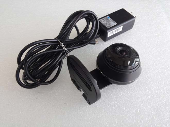
NLMSNHV6414BN
Nov 19, 2015SMART HOME CAMERA
Equipment Class
DTS - Digital Transmission System
NLMSEP1003RWN
Nov 16, 2015Wireless Baby Camera
Equipment Class
DSS - Part 15 Spread Spectrum Transmitter
NLMSEW3043WN
Nov 16, 2015Wireless Baby Monitor
Equipment Class
DSS - Part 15 Spread Spectrum Transmitter
NLMSEW3036W
Jun 16, 2015Baby Monitor
Equipment Class
DSS - Part 15 Spread Spectrum Transmitter
NLMSEP1001RW
Apr 27, 2015Baby Camera
Equipment Class
DSS - Part 15 Spread Spectrum Transmitter