NM8CENSUSHandheld Computer
HTC Corporation
Click to zoom
Application Details
- Equipment Class
- PCB - PCS Licensed Transmitter
- Date of Grant
- Oct 02, 2006
- Application Purpose
- Original Equipment
- Date of Application
- Oct 01, 2006
- Equipment Note
- Handheld Computer
- Frequency Range
- 824.12000000 - 848.76000000
- Company
- HTC Corporation
- Country
- Taiwan
Documents & Files
Document Text
Text extracted from the exhibit documents filed with the FCC. Open a document above to read the original.
Users Manual
User Manual 2 | Please Read Before Proceeding THIS DEVICE IS NOT CHARGED WHEN YOU TAKE IT OUT OF THE BOX. DO NOT REMOVE THE BATTERY PACK WHEN THE DEVICE IS CHARGING. YOUR WARRANTY IS INVALIDATED IF YOU OPEN OR TAMPER WITH THE DEVICE’S OUTER CASING. COPYRIGHT INFORMATION Microsoft, MS-DOS, Windows, Windows NT, Windows Server, Windows Mobile, ActiveSync, Excel, Internet Explorer, MSN, Outlook, PowerPoint, and Word are either registered trademarks or trademarks of Microsoft Corporation in the United States and/or other countries. All trademarks are the properties of their respective owners. | 3 Important Health Information and Safety Precautions When using this product, the safety precautions below must be taken to avoid possible legal liabilities and damages. Retain and follow all product safety and operating instructions. Observe all warnings in the operating instructions on the product. To reduce the risk of bodily injury, electric shock, fire, and damage to the equipment, observe the following precautions. ELECTRICAL SAFETY This product is intended for use when supplied with power from the designated battery or power supply unit.Other usage may be dangerous and will invalidate any approval given to this product. SAFETY PRECAUTIONS FOR PROPER GROUNDING AND CONNECTION CAUTION: Improper grounding when connecting the product to an associated equipment can result in a risk of electric shock. This product is equipped with a USB cable for connecting the product to a desktop or notebook computer. Be sure your computer is properly grounded (earthed) before connecting the product to the computer. The power supply cord of a desktop or notebook computer has an equipment- grounding conductor and a grounding plug. The plug must be plugged into an appropriate outlet which is properly installed and grounded in accordance with all local codes and ordinances. SAFETY PRECAUTIONS FOR POWER SUPPLY UNIT • Use the correct external power source A product should be operated only from the type of power source indicated on the electrical ratings label. If you are not sure of the type of power source required, consult your authorized service provider or local power company. For a product that operates from battery power or other sources, refer to the operating instructions that are included with the product. • Handle battery packs carefully This product contains a Li-ion Polymer battery. There is a risk of fire and burns if the battery pack is handled improperly. Do not attempt to open or service the battery pack. Do not disassemble, crush, puncture, short external contacts or circuits, dispose of in fire or water, or expose a battery pack to temperatures higher than 60 ̊C (140 ̊F). 4 | WARNING! DANGER OF EXPLOSION IF BATTERY IS INCORRECTLY REPLACED. TO REDUCE RISK OF FIRE OR BURNS, DO NOT DISASSEMBLE, CRUSH, PUNCTURE, SHORT EXTERNAL CONTACTS, EXPOSE TO TEMPERATURE ABOVE 60 ̊C (140 ̊F), OR DISPOSE OF IN FIRE OR WATER. REPLACE ONLY WITH SPECIFIED BATTERIES. RECYCLE OR DISPOSE OF USED BATTERIES ACCORDING TO THE LOCAL REGULATIONS OR REFERENCE GUIDE SUPPLIED WITH YOUR PRODUCT. SAFETY PRECAUTIONS FOR DIRECT SUNLIGHT Keep this product away from excessive moisture and extreme temperatures. Do not leave the product or its battery inside a vehicle or in places where the temperature may exceed 60°C (140°F), such as on a car dashboard, window sill, or behind a glass that is exposed to direct sunlight or strong ultraviolet light for extended periods of time. This may damage the product, overheat the battery, or pose a risk to the vehicle. ENVIRONMENT RESTRICTIONS Do not use this product in gas stations, fuel depots, chemical plants or where blasting operations are in progress, or in potentially explosive atmospheres such as fuelling areas, fuel storehouses, below deck on boats, fuel or chemical transfer or storage facilities, and areas where the air contains chemicals or particles, such as grain, dust, or metal powders. Please be aware that sparks in such areas could cause an explosion or fire resulting in bodily injury or even death. EXPLOSIVE ATMOSPHERES When in any area with a potentially explosive atmosphere or where flammable materials exist, the product should be turned off and the user should obey all signs and instructions. Sparks in such areas could cause an explosion or fire resulting in bodily injury or even death. Users are advised not to use the equipment at refueling points such as service or gas stations, and are reminded of the need to observe restrictions on the use of radio equipment in fuel depots, chemical plants, or where blasting operations are in progress. Areas with a potentially explosive atmosphere are often, but not always, clearly marked. These include fueling areas, below deck on boats, fuel or chemical transfer or storage facilities, and areas where the air contains chemicals or particles, such as grain, dust, or metal powders. | 5 ROAD SAFETY Vehicle drivers in motion are not permitted to use telephony services with handheld devices, except in the case of emergency. In some countries, using hands-free devices as an alternative is allowed. INTERFERENCE WITH MEDICAL EQUIPMENT FUNCTIONS This product may cause medical equipment to malfunction. The use of this device is forbidden in most hospitals and medical clinics. GENERAL PRECAUTIONS • Heed service markings Except as explained elsewhere in the Operating or Service documentation, do not service any product yourself. Service needed on components inside these compartments should be done by an authorized service technician or provider. • Damage requiring service Unplug the product from the electrical outlet and refer servicing to an authorized service technician or provider under the following conditions: • Liquid has been spilled or an object has fallen into the product. • The product has been exposed to rain or water. • The product has been dropped or damaged. • There are noticeable signs of overheating. • The product does not operate normally when…
Text truncated - open the document above for the full version.
External Photos
Page 1 CONSTRUCTION PHOTOS OF EUT Page 2 Page 3
ID Label/Location Info
PROPOSED FCC ID LABEL AND LOCATION High Tech Computer Corp. FCC ID: NM8CENSUS This device complies with Part 15 of the FCC Rules. Operation is subject to the following two conditions: (1) this device may not cause harmful interference, and (2) this device must accept any interference received, including interference that may cause undesired operation. Back of the EUT FCC ID Label
Internal Photos
Page 4 Page 5 Page 6 Page 7 Page 8 Page 9 Page 10 Page 11 Page 12 Page 13 Page 14
RF Exposure Info
FCC ID: NM8CENSUS Report No.: SA950817L14 1 RF EXPOSURE REPORT (PART 22) REPORT NO.: SA950817L14 MODEL NO.: CENSUS ACCORDING: FCC Guidelines for Human Exposure IEEE C95.1 APPLICANT: High Tech Computer Corp. ADDRESS: 23, Hsin-Hua Rd., Taoyuan, 330, Taiwan, R.O.C. ISSUED BY: Advance Data Technology Corporation LAB ADDRESS: No. 47, 14th Ling, Chia Pau Tsuen, Lin Kou Hsiang 244, Taipei Hsien, Taiwan, R.O.C. TEST LOCATION: No. 19, Hwa Ya 2 nd Rd., Wen Hwa Tsuen, Kwei Shan Hsiang, Taoyuan Hsien 333, Taiwan, R.O.C. FCC ID: NM8CENSUS Report No.: SA950817L14 2 RF Exposure Measurement (Handheld Device) 1. Introduction In this document, we try to prove the safety of radiation harmfulness to the human body for our product. The limit for Maximum Permissible Exposure (MPE) specified in FCC 1.1310 is followed. The Gain of the antenna used in this product is measured in a Fully Anechoic Chamber (FAC) calibrated for antenna measurement in ADT, and also the maximum total power input to the antenna is measured. Through the Friis transmission formula and the maximum gain of the antenna, we can calculate the distance, away from the product, where the limit of MPE is reached. Although the Friis transmission formula is a far field assumption, the calculated result of that is an over-prediction for near field power density. We will take that as the worst case to specify the safety range. 2. RF Exposure Limit According to FCC 1.1310: The criteria listed in the following table shall be used to evaluate the environmental impact of human exposure to radio-frequency (RF) radiation as specified in 1.1307(b) LIMITS FOR MAXIMUM PERMISSIBLE EXPOSURE (MPE) Frequency Range (MHz) Electric Field Strength (V/m) Magnetic Field Strength (A/m) Power Density (mW/cm 2 ) Average Time (minutes) (A)Limits For Occupational / Control Exposures 300-1500......F/3006 1500-100,000......56 (B)Limits For General Population / Uncontrolled Exposure 300-1500......F/15006 1500-100,000......1.030 F = Frequency in MHz FCC ID: NM8CENSUS Report No.: SA950817L14 3 3. Friis Formula Friis transmission formula : Pd = (Pout*G) / (4*pi*r 2 ) where Pd = power density in mW/cm 2 Pout = output power to antenna in mW G = gain of antenna in linear scale Pi = 3.1416 R = distance between observation point and center of the radiator in cm If we know the maximum Gain of the antenna and the total power input to the antenna, through the calculation, we will know the MPE value at distance r. Ref. : David K. Cheng, Field and Wave Electromagnetics, Second Edition, Page 640, Eq. (11-133). 4. EUT Operating condition The software provided by Manufacturer enabled the EUT to transmit and receive data at lowest, middle and highest channel individually. 5. Classification The antenna of the product, under normal use condition, is at least 20cm away from the body of the user. Warning statement for keeping 20cm separation distance and the prohibition of operating next to a person has been printed on the user’s manual. So, this product is classified as the Handheld Device. FCC ID: NM8CENSUS Report No.: SA950817L14 4 6. Test Results 6.1 Antenna Gain Since the maximum eirp power is used as the peak output power to antenna, so the Gain of the antenna can be assumed as 2.15dBi. 6.2 Output Power into Antenna & RF Exposure value at distance 20cm: Channel Channel Frequency (MHz) Output Power to Antenna (mW) Power Density (mW/cm 2 ) Limit of Power Density (mW/cm 2 ) 1013824.12157.7610.0511.0 384836.58155.9550.0511.0 777848.76161.0650.0531.0
RF Exposure Info
FCC ID: NM8CENSUS Report No.: SA950817L14 1 RF EXPOSURE REPORT (PART 24) REPORT NO.: SA950817L14 MODEL NO.: CENSUS ACCORDING: FCC Guidelines for Human Exposure IEEE C95.1 APPLICANT: High Tech Computer Corp. ADDRESS: 23, Hsin-Hua Rd., Taoyuan, 330, Taiwan, R.O.C. ISSUED BY: Advance Data Technology Corporation LAB ADDRESS: No. 47, 14th Ling, Chia Pau Tsuen, Lin Kou Hsiang 244, Taipei Hsien, Taiwan, R.O.C. TEST LOCATION: No. 19, Hwa Ya 2 nd Rd., Wen Hwa Tsuen, Kwei Shan Hsiang, Taoyuan Hsien 333, Taiwan, R.O.C. FCC ID: NM8CENSUS Report No.: SA950817L14 2 RF Exposure Measurement (Handheld Device) 1. Introduction In this document, we try to prove the safety of radiation harmfulness to the human body for our product. The limit for Maximum Permissible Exposure (MPE) specified in FCC 1.1310 is followed. The Gain of the antenna used in this product is measured in a Fully Anechoic Chamber (FAC) calibrated for antenna measurement in ADT, and also the maximum total power input to the antenna is measured. Through the Friis transmission formula and the maximum gain of the antenna, we can calculate the distance, away from the product, where the limit of MPE is reached. Although the Friis transmission formula is a far field assumption, the calculated result of that is an over-prediction for near field power density. We will take that as the worst case to specify the safety range. 2. RF Exposure Limit According to FCC 1.1310: The criteria listed in the following table shall be used to evaluate the environmental impact of human exposure to radio-frequency (RF) radiation as specified in 1.1307(b) LIMITS FOR MAXIMUM PERMISSIBLE EXPOSURE (MPE) Frequency Range (MHz) Electric Field Strength (V/m) Magnetic Field Strength (A/m) Power Density (mW/cm 2 ) Average Time (minutes) (A)Limits For Occupational / Control Exposures 300-1500......F/3006 1500-100,000......56 (B)Limits For General Population / Uncontrolled Exposure 300-1500......F/15006 1500-100,000......1.030 F = Frequency in MHz FCC ID: NM8CENSUS Report No.: SA950817L14 3 3. Friis Formula Friis transmission formula : Pd = (Pout*G) / (4*pi*r 2 ) where Pd = power density in mW/cm 2 Pout = output power to antenna in mW G = gain of antenna in linear scale Pi = 3.1416 R = distance between observation point and center of the radiator in cm If we know the maximum Gain of the antenna and the total power input to the antenna, through the calculation, we will know the MPE value at distance r. Ref. : David K. Cheng, Field and Wave Electromagnetics, Second Edition, Page 640, Eq. (11-133). 4. EUT Operating condition The software provided by Manufacturer enabled the EUT to transmit and receive data at lowest, middle and highest channel individually. 5. Classification The antenna of the product, under normal use condition, is at least 20cm away from the body of the user. Warning statement for keeping 20cm separation distance and the prohibition of operating next to a person has been printed on the user’s manual. So, this product is classified as the Handheld Device. FCC ID: NM8CENSUS Report No.: SA950817L14 4 6. Test Results 6.1 Antenna Gain Since the maximum eirp power is used as the peak output power to antenna, so the Gain of the antenna can be assumed as 0dBi. 6.2 Output Power into Antenna & RF Exposure value at distance 20cm: Channel Channel Frequency (MHz) Output Power to Antenna (mW) Power Density (mW/cm 2 ) Limit of Power Density (mW/cm 2 ) 251851.25243.7810.0481.0 6001880.00293.7650.0581.0 11751908.75270.3960.0541.0
Test Report
Report no.: RF950817L141Report Format Version 2.0.4 FCC TEST REPORT for CDMA (PART 22) REPORT NO.: RF950817L14 MODEL NO.: CENSUS RECEIVED: Aug. 18, 2006 TESTED: Aug. 23 ~ 28, 2006 ISSUED: Sep. 04, 2006 APPLICANT: High Tech Computer Corp. ADDRESS: 23, Hsin-Hua Rd., Taoyuan, 330, Taiwan, R.O.C. ISSUED BY: Advance Data Technology Corporation LAB ADDRESS: No. 47, 14th Ling, Chia Pau Tsuen, Lin Kou Hsiang 244, Taipei Hsien, Taiwan, R.O.C. TEST LOCATION: No. 19, Hwa Ya 2 nd Rd., Wen Hwa Tsuen, Kwei Shan Hsiang, Taoyuan Hsien 333, Taiwan, R.O.C. This test report consists of 48 pages in total. It may be duplicated completely for legal use with the approval of the applicant. It should not be reproduced except in full, without the written approval of our laboratory. The client should not use it to claim product endorsement by CNLA, A2LA or any government agencies. The test results in the report only apply to the tested sample. Report no.: RF950817L142Report Format Version 2.0.4 TABLE OF CONTENTS 1CERTIFICATION......................................................................................................4 2SUMMARY OF TEST RESULTS.............................................................................5 2.1MEASUREMENT UNCERTAINTY...........................................................................6 3GENERAL INFORMATION......................................................................................7 3.1GENERAL DESCRIPTION OF EUT........................................................................7 3.2DESCRIPTION OF TEST MODES..........................................................................9 3.3GENERAL DESCRIPTION OF APPLIED STANDARDS........................................10 3.4DESCRIPTION OF SUPPORT UNITS...................................................................10 4TEST TYPES AND RESULTS...............................................................................11 4.1OUTPUT POWER MEASUREMENT.....................................................................11 4.1.1LIMITS OF OUTPUT POWER MEASUREMENT...................................................11 4.1.2TEST INSTRUMENTS...........................................................................................12 4.1.3TEST PROCEDURES...........................................................................................13 4.1.4TEST SETUP........................................................................................................14 4.1.5EUT OPERATING CONDITIONS...........................................................................15 4.1.6TEST RESULTS....................................................................................................16 4.2FREQUENCY STABILITY MEASUREMENT.........................................................18 4.2.1LIMITS OF FREQUENCY STABILIITY MEASUREMENT......................................18 4.2.2TEST INSTRUMENTS...........................................................................................18 4.2.3TEST PROCEDURE..............................................................................................19 4.2.4TEST SETUP........................................................................................................19 4.2.5TEST RESULTS....................................................................................................20 4.3OCCUPIED BANDWIDTH MEASUREMENT.........................................................21 4.3.1LIMITS OF OCCUPIED BANDWIDTH MEASUREMENT.......................................21 4.3.2TEST INSTRUMENTS...........................................................................................21 4.3.3TEST SETUP........................................................................................................21 4.3.4TEST PROCEDURES...........................................................................................22 4.3.5EUT OPERATING CONDITION.............................................................................22 4.3.6TEST RESULTS....................................................................................................22 4.4BAND EDGE MEASUREMENT.............................................................................25 4.4.1LIMITS OF BAND EDGE MEASUREMENT...........................................................25 4.4.2TEST INSTRUMENTS...........................................................................................25 4.4.3TEST SETUP........................................................................................................25 4.4.4TEST PROCEDURES...........................................................................................26 4.4.5EUT OPERATING CONDITION.............................................................................26 4.4.6TEST RESULTS....................................................................................................27 4.5CONDUCTED SPURIOUS EMISSIONS................................................................28 4.5.1LIMITS OF CONDUCTED SPURIOUS EMISSIONS MEASUREMENT.................28 4.5.2TEST INSTRUMENTS...........................................................................................28 4.5.3TEST PROCEDURE..............................................................................................29 4.5.4TEST SETUP........................................................................................................29 4.5.5EUT OPERATING CONDITIONS...........................................................................29 4.5.6TEST RESULTS....................................................................................................30 Report no.: RF950817L143Report Format Version 2.0.4 4.6RADIATED EMISSION MEASUREMENT (BELOW 1GHz)....................................36 4.6.1LIMITS OF RADIATED EMISSION MEASUREMENT............................................36 4.6.2TEST INSTRUMENTS...........................................................................................37 4.6.3TES…
Text truncated - open the document above for the full version.
Test Report
Report No.: RF950817L141Report Format Version 2.0.4 FCC TEST REPORT for CDMA (PART 24) REPORT NO.: RF950817L14 MODEL NO.: CENSUS RECEIVED: Aug. 18, 2006 TESTED: Aug. 23 ~ 28, 2006 ISSUED: Sep. 04, 2006 APPLICANT: High Tech Computer Corp. ADDRESS: 23, Hsin-Hua Rd., Taoyuan, 330, Taiwan, R.O.C. ISSUED BY: Advance Data Technology Corporation LAB ADDRESS: No. 47, 14th Ling, Chia Pau Tsuen, Lin Kou Hsiang 244, Taipei Hsien, Taiwan, R.O.C. TEST LOCATION: No. 19, Hwa Ya 2 nd Rd., Wen Hwa Tsuen, Kwei Shan Hsiang, Taoyuan Hsien 333, Taiwan, R.O.C. This test report consists of 48 pages in total. It may be duplicated completely for legal use with the approval of the applicant. It should not be reproduced except in full, without the written approval of our laboratory. The client should not use it to claim product endorsement by CNLA, A2LA or any government agencies. The test results in the report only apply to the tested sample. Report No.: RF950817L142Report Format Version 2.0.4 TABLE OF CONTENTS 1CERTIFICATION......................................................................................................4 2SUMMARY OF TEST RESULTS.............................................................................5 2.1MEASUREMENT UNCERTAINTY...........................................................................6 3GENERAL INFORMATION......................................................................................7 3.1GENERAL DESCRIPTION OF EUT........................................................................7 3.2DESCRIPTION OF TEST MODES..........................................................................9 3.3GENERAL DESCRIPTION OF APPLIED STANDARDS........................................10 3.4DESCRIPTION OF SUPPORT UNITS...................................................................10 4TEST TYPES AND RESULTS...............................................................................11 4.1OUTPUT POWER MEASUREMENT.....................................................................11 4.1.1LIMITS OF OUTPUT POWER MEASUREMENT...................................................11 4.1.2TEST INSTRUMENTS...........................................................................................12 4.1.3TEST PROCEDURES...........................................................................................13 4.1.4TEST SETUP........................................................................................................14 4.1.5EUT OPERATING CONDITIONS...........................................................................15 4.1.6TEST RESULTS....................................................................................................16 4.2FREQUENCY STABILITY MEASUREMENT.........................................................18 4.2.1LIMITS OF FREQUENCY STABILIITY MEASUREMENT......................................18 4.2.2TEST INSTRUMENTS...........................................................................................18 4.2.3TEST PROCEDURE..............................................................................................19 4.2.4TEST SETUP........................................................................................................19 4.2.5TEST RESULTS....................................................................................................20 4.3OCCUPIED BANDWIDTH MEASUREMENT.........................................................21 4.3.1LIMITS OF OCCUPIED BANDWIDTH MEASUREMENT.......................................21 4.3.2TEST INSTRUMENTS...........................................................................................21 4.3.3TEST SETUP........................................................................................................21 4.3.4TEST PROCEDURES...........................................................................................22 4.3.5EUT OPERATING CONDITION.............................................................................22 4.3.6TEST RESULTS....................................................................................................22 4.4BAND EDGE MEASUREMENT.............................................................................25 4.4.1LIMITS OF BAND EDGE MEASUREMENT...........................................................25 4.4.2TEST INSTRUMENTS...........................................................................................25 4.4.3TEST SETUP........................................................................................................25 4.4.4TEST PROCEDURES...........................................................................................26 4.4.5EUT OPERATING CONDITION.............................................................................26 4.4.6TEST RESULTS....................................................................................................27 4.5CONDUCTED SPURIOUS EMISSIONS................................................................28 4.5.1LIMITS OF CONDUCTED SPURIOUS EMISSIONS MEASUREMENT.................28 4.5.2TEST INSTRUMENTS...........................................................................................28 4.5.3TEST PROCEDURE..............................................................................................29 4.5.4TEST SETUP........................................................................................................29 4.5.5EUT OPERATING CONDITIONS...........................................................................29 4.5.6TEST RESULTS....................................................................................................30 Report No.: RF950817L143Report Format Version 2.0.4 4.6RADIATED EMISSION MEASUREMENT (BELOW 1GHz)....................................36 4.6.1LIMITS OF RADIATED EMISSION MEASUREMENT............................................36 4.6.2TEST INSTRUMENTS...........................................................................................37 4.6.3TES…
Text truncated - open the document above for the full version.
Test Setup Photos
1 PHOTOGRAPHS OF THE TEST CONFIGURATION Part 22 & Part 24 RADIATED EMISSION TEST
Contact Information
Applicant
Sylvia Shen
Technical Contact
Advance Data Technology Corporation (Hwa Ya)Gary Chang
[email protected]886-3-3183232
No. 19, Hwa Ya 2nd Rd., Kwei Shan Hsiang · Taoyuan Hsien · Taiwan
Non-Technical Contact
Advance Data Technology CorporationEllis Wu
[email protected]886-3-3183232
Test Firm
Bureau Veritas CPS (H.K.) Ltd. Taoyuan BranchRichard Chen
Technical Specifications
| # | Rule Parts | Frequency Range | Power Output | Emission | Tolerance |
|---|---|---|---|---|---|
| 2 | 22H | 824.12 MHz - 848.76 MHz | 161.00 mW | 1M44F9W | 0.1 ppm |
Other Applications from HTC Corporation
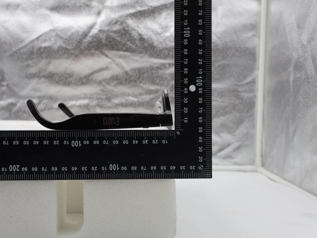
NM82QDJ100
Dec 31, 2025VIVE Headset
Equipment Class
DSS - Part 15 Spread Spectrum TransmitterNM82QD4100
Sep 01, 2024Headset
Equipment Class
6XD - 15E 6 GHz Low Power Indoor Client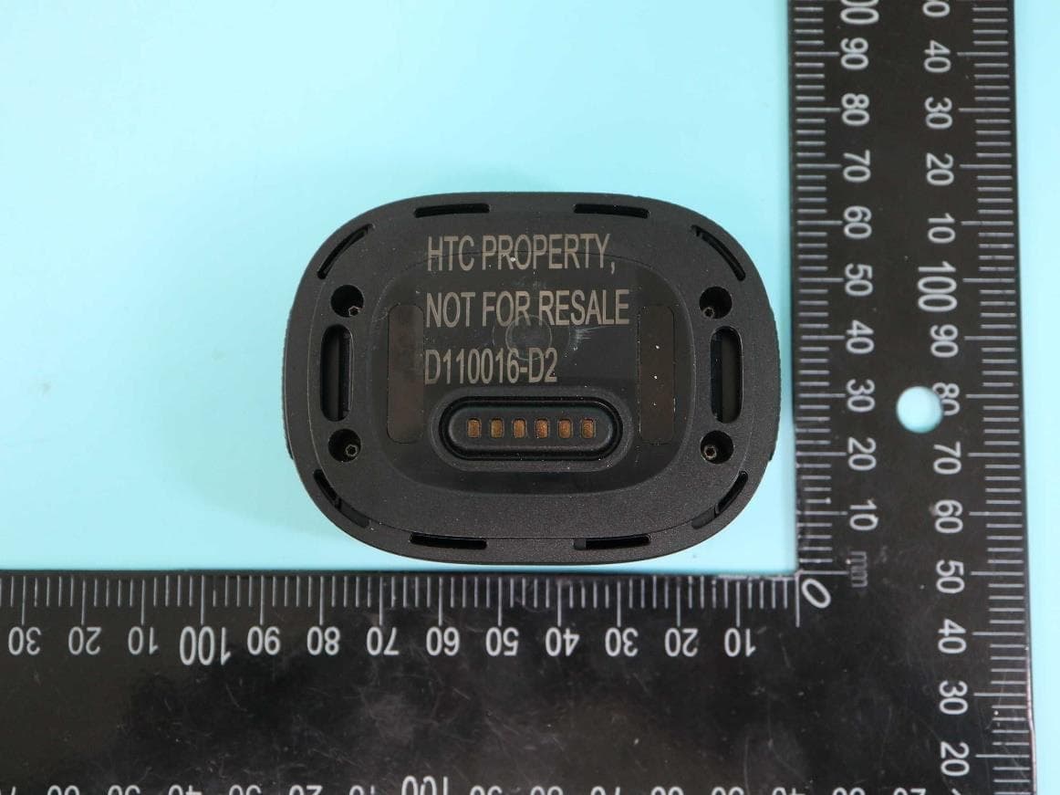
NM82QBP100
May 10, 2023Tracker
Equipment Class
DTS - Digital Transmission System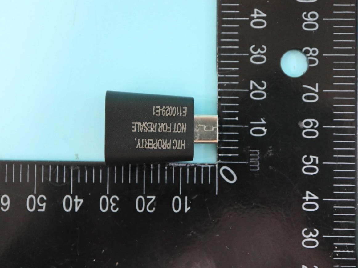
NM82QCD100
May 07, 2023Dongle
Equipment Class
DTS - Digital Transmission System
NM82QBB100
Jan 08, 2023Headset
Equipment Class
DTS - Digital Transmission System