NM8DGH300Media Link HD
HTC Corporation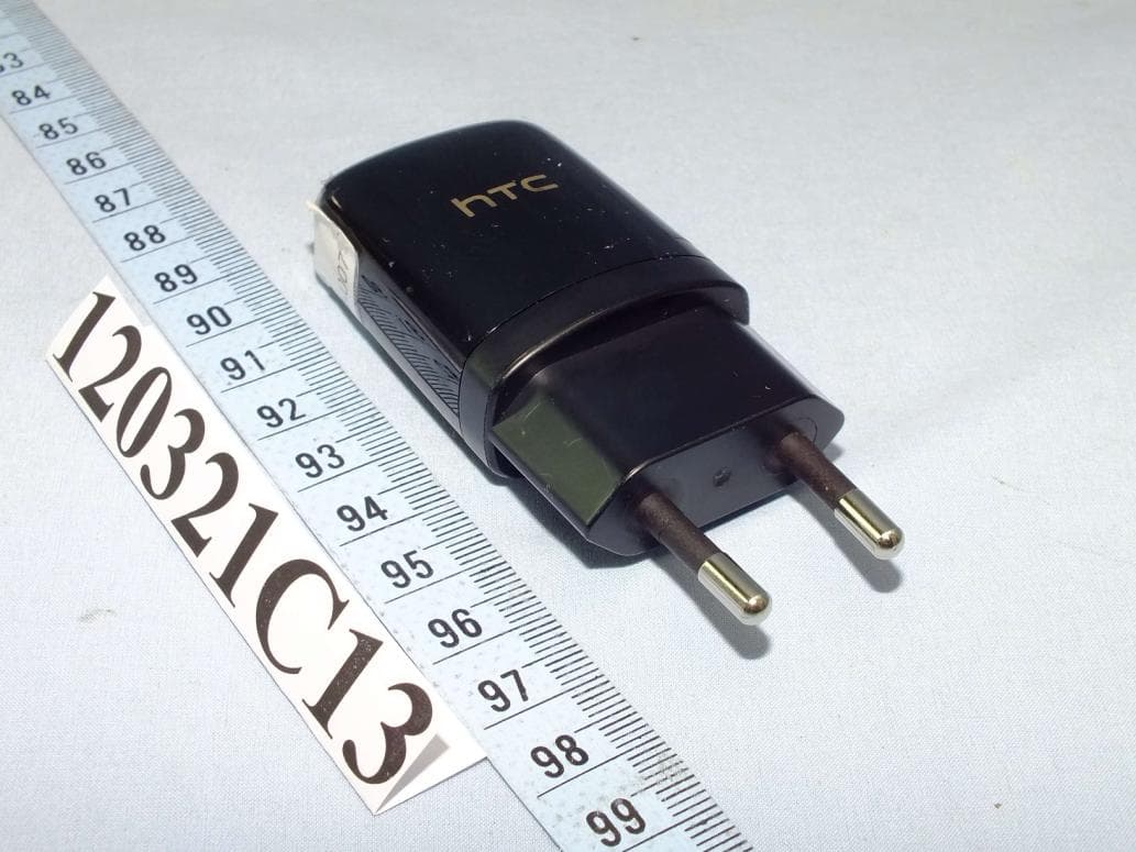
Click to zoom
Application Details
- Equipment Class
- DTS - Digital Transmission System
- Date of Grant
- May 29, 2012
- Application Purpose
- Original Equipment
- Date of Application
- May 29, 2012
- Equipment Note
- Media Link HD
- Frequency Range
- 5745.00000000 - 5825.00000000
- Company
- HTC Corporation
- Country
- Taiwan
Documents & Files
Document Text
Text extracted from the exhibit documents filed with the FCC. Open a document above to read the original.
Users Manual
User guide Your HTC Media Link HD DG-H300 for Certification DG-H300 for Certification DG-H300 for Certification 2 HTC Media Link HD This user guide will help you get started with your HTC Media Link HD. Please also read the Safety and regulatory guide that’s included in the box. Contents What’s in the box 3 Getting to know your Media Link HD 3 Setting up Media Link HD 5 Getting Media Link HD to recognize your phone 7 Sharing on a big screen 8 Changing Media Link HD settings 9 Keeping your Media Link HD updated 10 Resetting your Media Link HD 11 Helpful tips 12 Specifications 14 Trademarks and copyrights 15 DG-H300 for Certification DG-H300 for Certification DG-H300 for Certification User guide 3 What’s in the box Here’s what you should find when you open the box: • HTC Media Link HD • Power adapter • microUSB cable • HDMI cable • This user guide • Safety and regulatory guide ImportantUse HTC original accessories with your Media Link HD. Getting to know your Media Link HD Do you have a crowd of people squinting to watch that cool video on your phone? Use Media Link HD to wirelessly show the video on your big screen TV. Share photos and music, too. Before using Media Link HD, make sure that you have: a compatible HTC phone a TV with an HDMI® port NoteAvailable features depend on the phone model. Mirror mode is not supported on HTC One V. DisclaimerSome c ontent providers restrict the use of their content. You should always respect the terms of use of any content you intend to display on a TV using Media Link HD. If you try to play content using Media Link HD which you are not allowed to display on a TV, the content may not be displayed properly or at all. DG-H300 for Certification DG-H300 for Certification DG-H300 for Certification 4 HTC Media Link HD Here’s what Media Link HD looks like from the top, front and bottom. microUSB port HDMI port PBC button The PBC (Push Button Configuration) button only needs to be used if you need to reconfigure the network settings on your Media Link HD. The microUSB port is only used for supplying power to Media Link HD. The HDMI port connects Media Link HD to your TV. DG-H300 for Certification DG-H300 for Certification DG-H300 for Certification User guide 5 Setting up Media Link HD Connecting Media Link HD to your TV 1. Use the supplied microUSB cable to connect the power adapter to Media Link HD. 2. Plug in the power adapter to an electrical outlet. 3. Connect the supplied HDMI cable to the HDMI port on the bottom side of your Media Link HD. 4. Connect the other end of the HDMI cable to your TV. DG-H300 for Certification DG-H300 for Certification DG-H300 for Certification 6 HTC Media Link HD 5. On your TV, make sure you have selected the correct HDMI input in your TV’s input settings. You’ll then see the Media Link HD screen on your TV. Connecting your phone to your home network Connect your phone to your home network through your phone’s Wi-Fi settings. Refer to your phone’s user manual to find out how to set up a Wi-Fi connection. NotePeer-to-peer connection will be used in the following situations: A Wi-Fi router is unavailable or inaccessible. IP multi-casting is blocked on the network. TipYour Media Link HD will have better performance if the Wi-Fi signal is strong. DG-H300 for Certification DG-H300 for Certification DG-H300 for Certification User guide 7 Getting Media Link HD to recognize your phone ImportantMake sure your Media Link HD is already on and connected to your TV. When connecting to Media Link HD for the first time, simply swipe three fingers in an upwards direction on your phone. Media Link HD will then automatically configure itself. Whenever you want to share on your TV, you’ll only have to swipe up with three fingers to connect your phone to Media Link HD. To stop sharing, simply swipe down with three fingers. DG-H300 for Certification DG-H300 for Certification DG-H300 for Certification 8 HTC Media Link HD Sharing on a big screen Use your Media Link HD to share your movies, photos, and videos with your family and friends. 1. Connect your phone to Media Link HD using the three finger swipe. 2. Then start using the app that you want to share from. While playing movies from HTC Watch or viewing photos and videos in Gallery, you can also check your email, chat with friends, browse the web and more. DG-H300 for Certification DG-H300 for Certification DG-H300 for Certification User guide 9 Changing Media Link HD settings Switching to another language Prefer to see the onscreen text in a different language? You can change the language that is displayed on the TV screen. 1. On your phone, slide open the Notifications panel. 2. Tap Settings > More > Media Link HD. 3. Select your Media Link HD device. 4. Tap Advanced settings. 5. Select the language you want and then tap Save. NoteAdvanced settings is only accessible when the following two conditions are met. 1. Your Media Link HD is listed under “Available devices” in Settings > More > Media Link HD. 2. Your Media Link HD is set to “Off” in Settings > More > Media Link HD. Changing to a new Wi-Fi router If you changed to a new Wi-Fi router, simply connect your phone to it. Media Link HD will automatically connect to the new Wi-Fi router. But if you’re also trying to connect to Media Link HD with another phone, you’ll be asked to press the PBC button on Media Link HD to start the auto-configuration process. DG-H300 for Certification DG-H300 for Certification DG-H300 for Certification 10 HTC Media Link HD Keeping your Media Link HD updated Your Media Link HD automatically checks for firmware updates regularly. The firmware is downloaded and installed when you are not actively using Media Link HD. NoteFor your Media Link HD to automatically check for firmware updates, it needs to have Internet access through your Wi-Fi router. You can also manually check for updates in Advanced settings. 1. On your phone, slide open the Notifications panel. 2. Tap Settings > More > Media Link HD. 3. Sele…
Text truncated - open the document above for the full version.
Users Manual
Safety and regulatory guide 2 Safety and regulatory guide Please read before proceeding YOUR WARRANTY IS INVALIDATED IF YOU DISASSEMBLE OR ATTEMPT TO DISASSEMBLE THE DEVICE. Limitation of damages TO THE MAXIMUM EXTENT PERMITTED BY APPLICABLE LAW, IN NO EVENT SHALL HTC OR ITS AFFILIATES BE LIABLE TO YOU, ANY USER, OR THIRD PARTY FOR ANY INDIRECT, SPECIAL, CONSEQUENTIAL, INCIDENTAL OR PUNITIVE DAMAGES OF ANY KIND, ARISING IN CONTRACT, TORT, OR OTHERWISE, INCLUDING, BUT NOT LIMITED TO, INJURY, LOSS OF REVENUE, LOSS OF GOODWILL, LOSS OF BUSINESS OPPORTUNITY, LOSS OF DATA, AND/OR LOSS OF PROFITS, REGARDLESS OF THE FORESEEABILITY THEREOF OR WHETHER HTC OR ITS AFFILIATES HAVE BEEN ADVISED OF THE POSSIBILITY OF SUCH DAMAGES. AND IN NO EVENT SHALL THE TOTAL LIABILITY OF HTC OR ITS AFFILIATES EXCEED THE AMOUNT RECEIVED FROM YOU, REGARDLESS OF THE LEGAL THEORY UNDER WHICH THE CAUSE OF ACTION IS BROUGHT. THE FOREGOING DOES NOT AFFECT ANY STATUTORY RIGHTS WHICH MAY NOT BE DISCLAIMED. Important health information and safety precautions When using this product, the safety precautions below must be taken to avoid possible legal liabilities and damages. Retain and follow all product safety and operating instructions. Observe all warnings in the operating instructions on the product. To reduce the risk of bodily injury, electric shock, fire, and damage to the equipment, observe the following precautions. Electrical safety This product is intended for use when supplied with power from the designated power supply unit. Other usage may be dangerous and will invalidate any approval given to this product. Safety precautions for proper grounding installation CAUTION: Connecting to improperly grounded equipment can result in an electric shock to your device. Safety and regulatory guide 3 The plug must be plugged into an appropriate outlet which is properly installed and grounded in accordance with all local codes and ordinances. Safety precautions for power supply unit Use the correct external power source A product should be operated only from the type of power source indicated on the electrical ratings label. If you are not sure of the type of power source required, consult your authorized service provider or local power company. For a product that operates from battery power or other sources, refer to the operating instructions that are included with the product. This product should be operated only with the following designated power supply unit(s). AC adapter: HTC, Model TC C250, TC U250, TC E250, TC A250, TC K250, and TC B250. Take extra precautions • Keep the device dry and away from water or any liquid as it may cause a short circuit. • Keep metal objects away so they don’t come in contact with the connectors as it may lead to short circuit during operation. Safety precautions for direct sunlight Keep this product away from excessive moisture and extreme temperatures. Do not leave the product inside a vehicle or in places where the temperature may exceed 60°C (140°F), such as on a car dashboard, window sill, or behind a glass that is exposed to direct sunlight or strong ultraviolet light for extended periods of time. This may damage the product or pose a risk to the vehicle. Safety in aircraft Due to the possible interference caused by this product to an aircraft’s navigation system and its communications network, using this device on board an airplane is against the law in most countries. Environment restrictions Do not use this product in gas stations, fuel depots, chemical plants or where blasting operations are in progress, or in 4 Safety and regulatory guide potentially explosive atmospheres such as fuelling areas, fuel storehouses, below deck on boats, chemical plants, fuel or chemical transfer or storage facilities, and areas where the air contains chemicals or particles, such as grain, dust, or metal powders. Please be aware that sparks in such areas could cause an explosion or fire resulting in bodily injury or even death. Explosive atmospheres When in any area with a potentially explosive atmosphere or where flammable materials exist, the product should be turned off and the user should obey all signs and instructions. Sparks in such areas could cause an explosion or fire resulting in bodily injury or even death. Users are advised not to use the equipment at refueling points such as service or gas stations, and are reminded of the need to observe restrictions on the use of radio equipment in fuel depots, chemical plants, or where blasting operations are in progress. Areas with a potentially explosive atmosphere are often, but not always, clearly marked. These include fueling areas, below deck on boats, fuel or chemical transfer or storage facilities, and areas where the air contains chemicals or particles, such as grain, dust, or metal powders. Interference with medical equipment functions This product may cause medical equipment to malfunction. The use of this device is forbidden in most hospitals and medical clinics. If you use any other personal medical device, consult the manufacturer of your device to determine if they are adequately shielded from external RF energy. Your physician may be able to assist you in obtaining this information. Turn your device OFF in health care facilities when any regulations posted in these areas instruct you to do so. Hospitals or health care facilities may be using equipment that could be sensitive to external RF energy. Hearing aids Some digital wireless devices may interfere with some hearing aids. In the event of such interference, you may want to consult your service provider, or call the customer service line to discuss alternatives. Safety and regulatory guide 5 Electrical safety Accessories • Use only approved accessories. • Do not connect with incompatible products or accessories. • Take care not to touch or allow metal objects, such as coins or key rings, to contact or short-circuit the terminals. Faulty and damaged products • Do not attempt to …
Text truncated - open the document above for the full version.
External Photos
Page 1 CONSTRUCTION PHOTOS OF EUT The EUT has following accessories. NO. PRODUCT BRAND MODEL DESCRIPTION 1 Power Adapter 1 PHIHONG TC U/E 250 TC B270 I/P: 100-240Vac, 200mA O/P: 5Vdc, 1A 2 Power Adapter 2 DELTA TC U250 TC A250 I/P: 100-240Vac, 200mA O/P: 5Vdc, 1A 3 USB Cable 1 Foxconn DC M430 1m shielded cable without core 4 USB Cable 2 Foxlink DC M430 1m shielded cable without core 5 HDMI Cable 1 COXOC HC M110 1.8m shielded cable with two ferrite cores 6 HDMI Cable 2 POWER SOLUTION HC M110 1.8m shielded cable with two ferrite cores Page 2 Page 3 Page 4 Page 5 Page 6 Page 7 Page 8 Page 9 Page 10
ID Label/Location Info
Label FCC ID:NM8DGH300
ID Label/Location Info
Label Location FCC ID: NM8DGH300 Note: The FCC ID label shown will be readily visible to the purchaser at the time of purchase. Label location is on lower back of dongle
Internal Photos
Page 11 Page 12 Page 13 Page 14
RF Exposure Info
Report No.: SA120321C13A Report Format Version 4.0.0 Reference No.: 120516C14 1 RF EXPOSURE REPORT REPORT NO.: SA120321C13A MODEL NO.: DG H300 FCC ID: NM8DGH300 RECEIVED: Mar. 21, 2012 TESTED: Apr. 07 ~ Apr. 26, 2012 ISSUED: May 18, 2012 APPLICANT: HTC Corporation ADDRESS: No. 23, Xinghua Rd., Taoyuan City, Taiwan ISSUED BY: Bureau Veritas Consumer Products Services (H.K.) Ltd., Taoyuan Branch LAB ADDRESS: No. 47, 14th Ling, Chia Pau Vil., Lin Kou Dist., New Taipei City, Taiwan ( R.O.C ) TEST LOCATION: No. 19, Hwa Ya 2nd Rd, Wen Hwa Tsuen, Kwei Shan Hsiang, Taoyuan Hsien 333, Taiwan, R.O.C. This test report consists of 6 pages in total. It may be duplicated completely for legal use with the approval of the applicant. It should not be reproduced, except in full, without the written approval of our laboratory. The client should not use it to claim product, certification, approval, or endorsement by any government agency. The test results in the report only apply to the tested sample. Report No.: SA120321C13A Report Format Version 4.0.0 Reference No.: 120516C14 2 TABLE OF CONTENTS RELEASE CONTROL RECORD ............................................................................................... 3 1. CERTIFICATION ........................................................................................................... 4 2. RF EXPOSURE ............................................................................................................. 5 2.1 LIMITS FOR MAXIMUM PERMISSIBLE EXPOSURE (MPE) ........................................ 5 2.2 MPE CALCULATION FORMULA ................................................................................... 5 2.3 CLASSIFICATION ......................................................................................................... 5 2.4 CALCULATION RESULT OF MAXIMUM CONDUCTED POWER ................................. 6 Report No.: SA120321C13A Report Format Version 4.0.0 Reference No.: 120516C14 3 RELEASE CONTROL RECORD ISSUE NO. REASON FOR CHANGE DATE ISSUED SA120321C13A Original release May 18, 2012 Report No.: SA120321C13A Report Format Version 4.0.0 Reference No.: 120516C14 4 1. CERTIFICATION PRODUCT: Media Link HD MODEL: DG H300 BRAND: HTC APPLICANT: HTC Corporation TESTED: Apr. 07 ~ Apr. 26, 2012 TEST SAMPLE: Production Unit STANDARDS: FCC Part 2 (Section 2.1091) FCC OET Bulletin 65, Supplement C (01-01) IEEE C95.1 The above equipment have been evaluated by Bureau Veritas Consumer Products Services (H.K.) Ltd., Taoyuan Branch, and found compliance with the requirement of the above standards. The test record, data evaluation & Equipment Under Test (EUT) configurations represented herein are true and accurate accounts of the measurements of the sample’s EMC characteristics under the conditions specified in this report. PREPARED BY : , DATE : May 18, 2012 Ivonne Wu / Senior Specialist APPROVED BY : , DATE : May 18, 2012 Gary Chang / Technical Manager Report No.: SA120321C13A Report Format Version 4.0.0 Reference No.: 120516C14 5 2. RF EXPOSURE 2.1 LIMITS FOR MAXIMUM PERMISSIBLE EXPOSURE (MPE) FREQUENCY RANGE (MHz) ELECTRIC FIELD STRENGTH (V/m) MAGNETIC FIELD STRENGTH (A/m) POWER DENSITY (mW/cm 2 ) AVERAGE TIME (minutes) LIMITS FOR GENERAL POPULATION / UNCONTROLLED EXPOSURE 300-1500 ... ... F/1500 30 1500-100,000 ... ... 1.0 30 F = Frequency in MHz 2.2 MPE CALCULATION FORMULA Pd = (Pout*G) / (4*pi*r2) where Pd = power density in mW/cm2 Pout = output power to antenna in mW G = gain of antenna in linear scale Pi = 3.1416 R = distance between observation point and center of the radiator in cm 2.3 CLASSIFICATION The antenna of this product, under normal use condition, is at least 20cm away from the body of the user. So, this device is classified as Mobile Device. Report No.: SA120321C13A Report Format Version 4.0.0 Reference No.: 120516C14 6 2.4 CALCULATION RESULT OF MAXIMUM CONDUCTED POWER FREQUENCY BAND (MHz) MODULATION MODE MAX CONDUCTED POWER (dBm) ANTENNA GAIN (dBi) DISTANCE (cm) POWER DENSITY (mW/cm 2 ) LIMIT (mW/cm 2 ) 2412-2462 802.11b 18.63 2 20 0.023 1 802.11g 21.89 2 20 0.049 1 802.11n (20MHz) 21.03 2 20 0.040 1 802.11n (40MHz) 20.75 2 20 0.037 1 5180-5240 802.11a 13.42 1 20 0.006 1 802.11n (20MHz) 13.23 1 20 0.005 1 802.11n (40MHz) 12.16 1 20 0.004 1 5745-5825 802.11a 22.18 1 20 0.041 1 802.11n (20MHz) 22.14 1 20 0.041 1 802.11n (40MHz) 21.25 1 20 0.033 1
Test Report
Report No.: RF120321C13 1 Report Format Version 4.2.0 FCC TEST REPORT (15.247) REPORT NO.: RF120321C13 MODEL NO.: DG H300 FCC ID: NM8DGH300 RECEIVED: Mar. 21, 2012 TESTED: Apr. 07 ~ Apr. 26, 2012 ISSUED: May 10, 2012 APPLICANT: HTC Corporation ADDRESS: No. 23, Xinghua Rd., Taoyuan City, Taiwan ISSUED BY: Bureau Veritas Consumer Products Services (H.K.) Ltd., Taoyuan Branch LAB ADDRESS: No. 47, 14th Ling, Chia Pau Vil., Lin Kou Dist., New Taipei City, Taiwan ( R.O.C. ) TEST LOCATION: No. 19, Hwa Ya 2nd Rd, Wen Hwa Tsuen, Kwei Shan Hsiang, Taoyuan Hsien 333, Taiwan, R.O.C. This test report consists of 77 pages in total. It may be duplicated completely for legal use with the approval of the applicant. It should not be reproduced except in full, without the written approval of our laboratory. The client should not use it to claim product certification, approval or endorsement by TAF or any government agency. The test results in the report only apply to the tested sample. Report No.: RF120321C13 2 Report Format Version 4.2.0 TABLE OF CONTENTS RELEASE CONTROL RECORD ............................................................................................................ 5 1. CERTIFICATION ......................................................................................................................... 6 2. SUMMARY OF TEST RESULTS ................................................................................................ 7 2.1 MEASUREMENT UNCERTAINTY .............................................................................................. 7 3. GENERAL INFORMATION ......................................................................................................... 8 3.1 GENERAL DESCRIPTION OF EUT ........................................................................................... 8 3.2 DESCRIPTION OF TEST MODES ........................................................................................... 10 3.2.1 TEST MODE APPLICABILITY AND TESTED CHANNEL DETAIL ........................................... 11 3.3 DESCRIPTION OF SUPPORT UNITS ..................................................................................... 15 3.3.1 CONFIGURATION OF SYSTEM UNDER TEST ...................................................................... 16 3.4 GENERAL DESCRIPTION OF APPLIED STANDARDS .......................................................... 17 4. TEST TYPES AND RESULTS (FOR 2.4GHz BAND) ............................................................... 18 4.1 RADIATED EMISSION AND BANDEDGE MEASUREMENT .................................................. 18 4.1.1 LIMITS OF RADIATED EMISSION AND BANDEDGE MEASUREMENT ................................ 18 4.1.2 TEST INSTRUMENTS .............................................................................................................. 19 4.1.3 TEST PROCEDURES .............................................................................................................. 20 4.1.4 DEVIATION FROM TEST STANDARD .................................................................................... 20 4.1.5 TEST SETUP ............................................................................................................................ 21 4.1.6 EUT OPERATING CONDITIONS ............................................................................................. 21 4.1.7 TEST RESULTS........................................................................................................................ 22 4.2 CONDUCTED EMISSION MEASUREMENT ........................................................................... 35 4.2.1 LIMITS OF CONDUCTED EMISSION MEASUREMENT ........................................................ 35 4.2.2 TEST INSTRUMENTS .............................................................................................................. 35 4.2.3 TEST PROCEDURES .............................................................................................................. 36 4.2.4 DEVIATION FROM TEST STANDARD .................................................................................... 36 4.2.5 TEST SETUP ............................................................................................................................ 36 4.2.6 EUT OPERATING CONDITIONS ............................................................................................. 36 4.2.7 TEST RESULTS........................................................................................................................ 37 4.3 6dB BANDWIDTH MEASUREMENT ........................................................................................ 39 4.3.1 LIMITS OF 6dB BANDWIDTH MEASUREMENT ..................................................................... 39 4.3.2 TEST SETUP ............................................................................................................................ 39 4.3.3 TEST INSTRUMENTS .............................................................................................................. 39 4.3.4 TEST PROCEDURE ................................................................................................................. 39 4.3.5 DEVIATION FROM TEST STANDARD .................................................................................... 39 4.3.6 EUT OPERATING CONDITIONS ............................................................................................. 39 4.3.7 TEST RESULTS........................................................................................................................ 40 4.4 CONDUCTED OUTPUT POWER............................................................................................. 41 4.4.1 LIMITS OF CONDUCTED OUTPUT POWER MEASUREMENT ............................................. 41 4.4.2 TEST SETUP ............................................................................................................................ 41 4.4.3 TEST INSTRUMENTS .…
Text truncated - open the document above for the full version.
Test Report
Report No.: RF120321C13-1 1 Report Format Version 4.2.0 FCC TEST REPORT (15.407) REPORT NO.: RF120321C13-1 MODEL NO.: DG H300 FCC ID: NM8DGH300 RECEIVED: Mar. 21, 2012 TESTED: Apr. 08 ~ Apr. 26, 2012 ISSUED: May 10, 2012 APPLICANT: HTC Corporation ADDRESS: No. 23, Xinghua Rd., Taoyuan City, Taiwan ISSUED BY: Bureau Veritas Consumer Products Services (H.K.) Ltd., Taoyuan Branch LAB ADDRESS: No. 47, 14th Ling, Chia Pau Vil., Lin Kou Dist., New Taipei City, Taiwan ( R.O.C. ) TEST LOCATION: No. 19, Hwa Ya 2nd Rd, Wen Hwa Tsuen, Kwei Shan Hsiang, Taoyuan Hsien 333, Taiwan, R.O.C. This test report consists of 49 pages in total. It may be duplicated completely for legal use with the approval of the applicant. It should not be reproduced except in full, without the written approval of our laboratory. The client should not use it to claim product certification, approval or endorsement by TAF or any government agency. The test results in the report only apply to the tested sample. Report No.: RF120321C13-1 2 Report Format Version 4.2.0 TABLE OF CONTENTS RELEASE CONTROL RECORD .............................................................................................................. 4 1. CERTIFICATION .......................................................................................................................... 5 2. SUMMARY OF TEST RESULTS ................................................................................................. 6 2.1 MEASUREMENT UNCERTAINTY .............................................................................................. 6 3. GENERAL INFORMATION .......................................................................................................... 7 3.1 GENERAL DESCRIPTION OF EUT ............................................................................................ 7 3.2 DESCRIPTION OF TEST MODES .............................................................................................. 8 3.2.1 TEST MODE APPLICABILITY AND TESTED CHANNEL DETAIL ............................................. 9 3.3 DUTY CYCLE OF TEST SIGNAL ..............................................................................................10 3.4 DESCRIPTION OF SUPPORT UNITS ...................................................................................... 11 3.4.1 CONFIGURATION OF SYSTEM UNDER TEST .......................................................................12 3.5 GENERAL DESCRIPTION OF APPLIED STANDARDS ...........................................................13 4. TEST TYPES AND RESULTS ...................................................................................................14 4.1 RADIATED EMISSION AND BANDEDGE MEASUREMENT ...................................................14 4.1.1 LIMITS OF RADIATED EMISSION AND BANDEDGE MEASUREMENT.................................14 4.1.2 LIMITS OF UNWANTED EMISSION OUT OF THE RESTRICTED BANDS ............................14 4.1.3 TEST INSTRUMENTS ...............................................................................................................15 4.1.4 TEST PROCEDURES ...............................................................................................................16 4.1.5 DEVIATION FROM TEST STANDARD .....................................................................................16 4.1.6 TEST SETUP .............................................................................................................................17 4.1.7 EUT OPERATING CONDITION ................................................................................................17 4.1.8 TEST RESULTS ........................................................................................................................18 4.2 CONDUCTED EMISSION MEASUREMENT ............................................................................27 4.2.1 LIMITS OF CONDUCTED EMISSION MEASUREMENT .........................................................27 4.2.2 TEST INSTRUMENTS ...............................................................................................................27 4.2.3 TEST PROCEDURES ...............................................................................................................28 4.2.4 DEVIATION FROM TEST STANDARD .....................................................................................28 4.2.5 TEST SETUP .............................................................................................................................28 4.2.6 EUT OPERATING CONDITIONS ..............................................................................................28 4.2.7 TEST RESULTS ........................................................................................................................29 4.3 PEAK TRANSMIT POWER MEASUREMENT ..........................................................................31 4.3.1 LIMITS OF PEAK TRANSMIT POWER MEASUREMENT .......................................................31 4.3.2 TEST SETUP .............................................................................................................................31 4.3.3 TEST INSTRUMENTS ...............................................................................................................31 4.3.4 TEST PROCEDURE ..................................................................................................................32 4.3.5 DEVIATION FROM TEST STANDARD .....................................................................................32 4.3.6 EUT OPERATING CONDITIONS ..............................................................................................32 4.3.7 TEST RESULTS ........................................................................................................................33 4.4 PEAK POWER SPECTRAL DENSITY MEASUREMENT .........................................................35 4.4.1 LIMITS OF PEAK POWER SPECTRAL DENSITY MEASUREME…
Text truncated - open the document above for the full version.
Test Setup Photos
1 PHOTOGRAPHS OF THE TEST CONFIGURATION CONDUCTED EMISSION TEST 2 (FOR WLAN: 2.4GHz) RADIATED EMISSION TEST 3 (FOR WLAN: 5.0GHz) RADIATED EMISSION TEST
Contact Information
Applicant
Sylvia Shen
Technical Contact
Bureau Veritas CPS (H.K.) Ltd. Taoyuan BranchGary Chang
[email protected]886-3-3183232
No. 19, Hwa Ya 2nd Rd., Kwei Shan Hsiang · Taoyuan Hsien · Taiwan
Non-Technical Contact
Bureau Veritas CPS (H.K.) Ltd. Taoyuan BranchKim Huang
[email protected]886-3-3183232
Test Firm
Bureau Veritas CPS (H.K.) Ltd. Taoyuan BranchRichard Chen
Technical Specifications
| # | Rule Parts | Frequency Range | Power Output |
|---|---|---|---|
| 2 | 15C | 5.75 GHz - 5.83 GHz | 165.00 mW |
Other Applications from HTC Corporation
NM82QDJ100
Dec 31, 2025VIVE Headset
Equipment Class
DSS - Part 15 Spread Spectrum TransmitterNM82QD4100
Sep 01, 2024Headset
Equipment Class
6XD - 15E 6 GHz Low Power Indoor Client
NM82QBP100
May 10, 2023Tracker
Equipment Class
DTS - Digital Transmission System
NM82QCD100
May 07, 2023Dongle
Equipment Class
DTS - Digital Transmission System
NM82QBB100
Jan 08, 2023Headset
Equipment Class
DTS - Digital Transmission System