NM8HHH06CWLPocket PC Phone
HTC Corporation
Click to zoom
Application Details
- Equipment Class
- DTS - Digital Transmission System
- Date of Grant
- Nov 17, 2005
- Application Purpose
- Original Equipment
- Date of Application
- Oct 02, 2005
- Equipment Note
- Pocket PC Phone
- Frequency Range
- 2402.00000000 - 2480.00000000
- Company
- HTC Corporation
- Country
- Taiwan
Documents & Files
Document Text
Text extracted from the exhibit documents filed with the FCC. Open a document above to read the original.
Users Manual
Additional Product Information Trademark and Copyright Information © Copyright 2005 Hewlett-Packard Development Company, L.P. The information contained herein is subject to change without notice. The only warranties for HP products and services are set forth in the express warranty statements accompanying such products and services. Nothing herein should be construed as constituting an additional warranty. HP shall not be liable for technical or editorial errors or omissions contained herein. First Edition December 2005 Document Part Number: 399308-001 Phone l Powering On Phone Functions lMuting a Call lPutting a Call on Hold lChanging Phone Service Settings lForwarding Calls lBlocking Calls l Entering Voice Mail Or Text Messages Phone Number l Checking Connection and Signal Strength lMaking a Conference Call lManaging Calls Using Call History lMaking a Call From Call History lLocking and Unlocking The Phone l Changing the Current Profile l Changing the Ringer Volume http://www.hp.com lTaking Notes During A Call lMaking a Call By Entering a Contact Name l Making a Call From a Hyperlink Phone Number l Changing Phone Network Settings lManually Selecting a Phone Network lViewing Available Phone Networks lSetting Preferred Networks lLimiting Calls to Specific Area Codes or Phone Numbers l Inserting an International Country Code l Automatic Frequency Band Selection lCopying a Contact From a SIM to a Device lCreating a Voice Note lDeleting a Voice Note lListening to a Voice Note l Renaming a Voice Note l Viewing Call Timers l Resetting Call Timers lViewing Details About a Call lManaging GPS Automatically lSelecting A GPS Program Port lSpecifying the Hardware Port for a GPS Receiver Powering On Phone Functions To power on phone functions: Muting a Call During a call, you can mute your microphone so that the person with whom you are speaking cannot hear you, but you can still hear him or her. From the on-screen phone keypad, tap Mute. Putting a Call on Hold During a call, you can put the call on hold so you can call another number or answer an incoming 1.On the Today screen, tap iPAQ Wireless. 2.Tap the Phone tab, and then tap Status: Off to activate the phone radio. 3.Once the phone radio is on, press the green Answer/Send button on the keyboard to access the on-screen phone keypad or to answer or send a call. call. If you have more than one call on the line, you can switch between calls. Changing Phone Service Settings Once your phone service is set up through your mobile phone service provider, you can change service settings on your HP iPAQ. For example, you may want to block certain types of incoming and/or outgoing calls, forward incoming calls to a different phone number based on your situation, be notified of incoming calls when you are already in a phone session, or let others know your identity when making calls. To change service settings on the phone: Forwarding Calls Use call forwarding to forward incoming calls to a designated phone number. You can also use call forwarding to forward incoming calls for specific situations. For example: Blocking Calls 1.To put a call on hold, tap Hold. 2.To switch between calls, tap Swap. 1.Press the green Answer/Send button. 2.From the on-screen phone keypad, tap Menu > Options > Services tab. 3.Tap the service you want to change, and then tap the Get Settings button. 4.Make your changes and tap OK. 1.From the on-screen phone keypad, tap Menu > Options > Services tab. 2.Tap Call Forwarding > Get Settings button. 3.Select the Forward all incoming phone calls check box. 4.Enter the phone number that is to receive the forwarded calls. ?Select the No answer check box to forward calls when you cannot answer the phone. ? Select the Unavailable check box to forward calls when the phone is off. ? Select the Busy check box to forward calls when the line is busy. Use call barring to block certain types of calls. Entering Voice Mail Or Text Messages Phone Number To use voice mail or send text messages (SMS), you must enter the correct voice mail or text message phone number in Phone settings. To set up phone numbers: Checking Connection and Signal Strength When you insert your Subscriber Identity Module (SIM) card into your HP iPAQ, your unit automatically connects to your mobile phone service provider's network. The Phone icon indicates that you are connected. The more vertical bars in the icon, the better the connection. Making a Conference Call To make a conference call with two or more people: 1.From the on-screen phone keypad, tap Menu > Options > Services tab. 2.Tap Call Barring > Get Settings. 3.Select the type of calls you want to block. NOTE Sending text messages is not included in all network service plans. Ask your mobile service provider if your plan includes this service. 1.Press the green Answer/Send button. 2.From the on-screen keypad, tap Menu > Options > Services tab. 3.Tap Voice Mail and Text Messages > Get Settings button. 4.Enter the voice mail or text message phone number in the appropriate box. 5.Tap OK. 1.Tap the green Answer/Send button on the keyboard. 2.From the on-screen phone keypad, dial the first number. Managing Calls Using Call History Call History provides the time and duration of all incoming, outgoing, and missed calls, and a summary of total calls. Call History also provides easy access to notes taken during a call. Making a Call From Call History Use Call History to quickly call someone recently called or someone who recently called you. To make a call from Call History: Locking and Unlocking The Phone 3.Tap Talk. 4.Once you are connected, tap Hold. 5.Dial the second number. 6.Once you are connected, tap Menu > Conference. NOTE To add more parties to the conference call, dial each number, connect, and then tap Menu > Conference. ? To view Call History, from the on-screen phone keypad, tap Call History. ? To change the Call History view, tap Menu > Filter and select a different view. When filtering By Caller, you see a list…
Text truncated - open the document above for the full version.
Cover Letter(s)
1 Nov. 10, 2005 Applicant: High Tech Computer Corp FCC ID# NM8HHH06CWL Correspondence Reference Number: 29925 731 Confirmation Number: EA398603 Date of Original E-mail: 11/9/2005 The responses are as follows: 1) no-reponse requested FYI: user manual refers to IEEE Std 1528-200x draft 6.5 - this is incorrect because a draft is a "P" document (P1528) not a standard. Final standard is published as of Dec 2003 = IEEE Std 1528-2003. 2) Cover letter requests confid. for test setup photos. Presently SAR test setup photos are part of non- confidential exhibit also including SAR plots. If confid. is requested for these photos in SAR exhibit, please split and submit two separate exhibits - one into (EMC) test setup folder, and the other with SAR plots into RF Exposure folder. 3) SAR report mentions multislot class 10, and uses two transmit slots for body tests. What is mobile/terminal class? For terminal class A (voice and data simultan.), please address two-slot transmit for head positions. 4) In internal and/or external photos please add pointers/call-outs for locations of antennas relative to housing, or give pointer to within filing if info is already there. 5) Body-worn SAR tests with holster have only device front-face towards phantom. Please explain or give photos to show device will not be positioned with back-face towards a person's body. Response: 2) Thanks for your suggestion and we have removed the SAR test setup photos from the SAR plots, and have it relocated to EMC test setup photo. Please refer to revised EMC test setup photos “TSup_NM8HHH06CWL_rev.pdf “and “Test Rpt- SAR (Appendix A)_NM8HHH06CWL_rev3.pdf “. 3) The EUT is a terminal class B GPRS device; accordingly the two slots data transmission is not available during the voice operation, and hence head position evaluated is not applicable. 4) Thanks for the advice and we have revised the last three pages of the internal photo to show the location of each antenna by call-out mark. Please refer to submitted new document “Int pho_HSTNH-H06C-WL_rev.pdf “ 5) The characteristic of belt-clip design will not allow belt-clip to hold the EUT if it is in the reversed direction. (Please notice that the belt-clip holder has a directional curve that will seat the EUT only when its face toward the belt-clip). Please refer the submitted new document “belt clip description.pdf “ for detail.
External Photos
Page 1 CONSTRUCTION PHOTOS OF EUT M1 Page 2 Page 3 M2 Page 4 Page 5
ID Label/Location Info
PROPOSED FCC ID LABEL AND LOCATION High Tech Computer Corp. FCC ID: NM8HHH06CWL This device complies with Part 15 of the FCC Rules. Operation is subject to the following two conditions: (1) this device may not cause harmful interference, and (2) this device must accept any interference received, including interference that may cause undesired operation. Back of the EUT FCC ID Label
Internal Photos
Page 6 M1 Page 7 Page 8 Page 9 Page 10 Page 11 Page 12 Page 13 Page 14 Page 15 Page 16 Page 17 Page 18 Page 19 M2
Internal Photos
Page 6 M1 Page 7 Page 8 Page 9 Page 10 Page 11 Page 12 Page 13 Page 14 Page 15 Page 16 Page 17 Page 18 Page 19 Page 20 GSM Antenna Page 21 Wireless LAN Antenna Page 22 Bluetooth Antenna
Parts List/Tune Up Info
ItemDescriptionLocation
RF Exposure Info
D3: DAE SN: 579
RF Exposure Info
APPENDIX D: SYSTEM CERTIFICATE & CALIBRATION D1: SAM PHANTOM
RF Exposure Info
FCC ID: NM8HHH06CWL Report No.: SA940516L021Report Format Version 2.0.1 SAR TEST REPORT REPORT NO.: SA940516L02 MODEL NO.: HSTNH-H06C-WL RECEIVED: May 31, 2005 TESTED: Jun. 23 ~ Aug. 31, 2005 ISSUED: Sep. 09, 2005 APPLICANT: High Tech Computer Corp. ADDRESS: 1F, 6-3, Bau-Chian Rd., Hsin Tien, Taipei, Taiwan, R.O.C. ISSUED BY: Advance Data Technology Corporation LAB ADDRESS: No. 47, 14th Ling, Chia Pau Tsuen, Lin Kou Hsiang 244, Taipei Hsien, Taiwan, R.O.C. TEST LOCATION: No. 19, Hwa Ya 2 nd Rd., Wen Hwa Tsuen, Kwei Shan Hsiang, Taoyuan Hsien 333, Taiwan, R.O.C. This test report consists of 67 pages in total except Appendix. It may be duplicated completely for legal use with the approval of the applicant. It should not be reproduced except in full, without the written approval of our laboratory. The client should not use it to claim product endorsement by CNLA, A2LA or any government agencies. The test results in the report only apply to the tested sample. 0528 ILAC MRA NO. 2177-01 FCC ID: NM8HHH06CWL Report No.: SA940516L022Report Format Version 2.0.1 TABLE OF CONTENTS 1.CERTIFICATION..................................................................................................................3 2.GENERAL INFORMATION...................................................................................................4 2.1GENERAL DESCRIPTION OF EUT.............................................................................4 2.2GENERAL DESCRIPTION OF APPLIED STANDARDS...............................................6 2.3GENERAL INOFRMATION OF THE SAR SYSTEM.....................................................6 2.4GENERAL DESCRIPTION OF THE SPATIAL PEAK SAR EVALUATION.....................9 3.DESCRIPTION OF SUPPORT UNITS................................................................................13 4.DESCRIPTION OF TEST POSITION..................................................................................14 4.1.DESCRIPTION OF TEST POSITION.........................................................................14 4.1.1.TOUCH/CHEEK TEST POSITION.............................................................................15 4.1.2.TILT TEST POSITION...............................................................................................16 4.1.3.BODY-WORN CONFIGURATION..............................................................................16 4.2.DESCRIPTION OF TEST MODE...............................................................................17 4.3.SUMMARY OF TEST RESULT..................................................................................19 5.TEST RESULTS.................................................................................................................22 5.1TEST PROCEDURES...............................................................................................22 5.2MEASURED SAR RESULTS.....................................................................................24 5.3SAR LIMITS..............................................................................................................44 5.4RECIPES FOR TISSUE SIMULATING LIQUIDS........................................................45 5.5TEST EQUIPMENT FOR TISSUE PROPERTY.........................................................54 6.SYSTEM VALIDATION.......................................................................................................55 6.1TEST EQUIPMENT...................................................................................................55 6.2TEST PROCEDURE.................................................................................................56 6.3VALIDATION RESULTS............................................................................................58 6.4SYSTEM VALIDATION UNCERTAINTIES.................................................................59 7.MEASUREMENT SAR PROCEDURE UNCERTAINTIES....................................................60 7.1.PROBE CALIBRATION UNCERTAINTY....................................................................60 7.2.ISOTROPY UNCERTAINTY......................................................................................61 7.3.BOUNDARY EFFECT UNCERTAINTY......................................................................61 7.4.PROBE LINEARITY UNCERTAINTY.........................................................................62 7.5.READOUT ELECTRONICS UNCERTAINTY.............................................................62 7.6.RESPONSE TIME UNCERTAINTY...........................................................................62 7.7.INTEGRATION TIME UNCERTAINTY.......................................................................63 7.8.PROBE POSITIONER MECHANICAL TOLERANCE.................................................64 7.9.PROBE POSITIONING.............................................................................................64 7.10.PHANTOM UNCERTAINTY......................................................................................65 7.11.DASY4 UNCERTAINTY BUDGET.............................................................................66 8.INFORMATION ON THE TESTING LABORATORIES.........................................................67 APPENDIX A: TEST DATA APPENDIX B: ADT SAR MEASUREMENT SYSTEM APPENDIX C: PHOTOGRAPHS OF SYSTEM VALIDATION APPENDIX D: SYSTEM CERTIFICATE & CALIBRATION APPENDIX E: TEST CONFIGURATIONS FCC ID: NM8HHH06CWL Report No.: SA940516L023Report Format Version 2.0.1 1. CERTIFICATION PRODUCT : Pocket PC Phone MODEL NO.: HSTNH-H06C-WL APPLICANT : High Tech Computer Corp. TESTED : Jun. 23 ~ Aug. 31, 2005 TEST SAMPLE : ENGINEERING SAMPLE STANDARDS : FCC Part 2 (Section 2.1093), FCC OET Bulletin 65, Supplement C (01-01), RSS-102 The above equipment have been tested by Advance Data Technology Corporation, and found compliance with the requirement of the above standards. The test record, data evaluation & Equipment Under Test (EUT) configurations represented herein ar…
Text truncated - open the document above for the full version.
RF Exposure Info
B - 1 APPENDIX B: ADT SAR MEASUREMENT SYSTEM C - 1 APPENDIX C: PHOTOGRAPHS OF SYSTEM VALIDATION
RF Exposure Info
Liquid Level Photo Tissue HSL835MHz D=150mm (Date:2005/6/24) Tissue MSL835MHz D=150mm (Date:2005/6/26) Tissue HSL1900MHz D=150mm (Date:2005/6/25) Tissue MSL1900MHz D=150mm (Date:2005/6/25) Tissue MSL2450MHz D=152mm (Date:2005/6/23) Tissue HSL835MHz D=155mm (Date:2005/8/29) Tissue MSL835MHz D=150mm (Date:2005/8/29) Tissue HSL1900MHz D=152mm (Date:2005/8/31) Tissue MSL1900MHz D=150mm (Date:2005/8/31) Tissue MSL2450MHz D=150mm (Date:2005/8/22) Date/Time: 2005/6/24 13:18:34 Test Laboratory: Advance Data Technology POCKET PC PHONE PCS850 Left Head DUT: POCKET PC PHONE ; Type: HSTNH-H06C-WL ; Test Frequency: 824.2 MHz Communication System: PCS 850 ; Frequency: 824.2 MHz ; Duty Cycle: 1:8.3 Medium: HSL850 Medium parameters used: f = 824.2 MHz; σ = 0.881 mho/m; ε r = 42.6; ρ = 1000 kg/m 3 ; Liquid level: 150mm Phantom section: Left Section ; DUT test position : Cheek ; Modulation type: GMSK Antenna type : Internal Antenna ; Air temp. : 22.0 degrees ; Liquid temp. : 21.0 degrees DASY4 Configuration: - Probe: ET3DV6 - SN1790; ConvF(6.94, 6.94, 6.94) ; Calibrated: 2004/12/20 - Sensor-Surface: 4mm (Mechanical Surface Detection) - Electronics: DAE3 Sn579; Calibrated: 2005/3/23 - Phantom: SAM 12; Type: SAM V4.0; Serial: TP 1202 - Measurement SW: DASY4, V4.5 Build 19; Postprocessing SW: SEMCAD, V1.8 Build 146 Touch position - Low Channel 128/Area Scan (9x10x1): Measurement grid: dx=15mm, dy=15mm Maximum value of SAR (measured) = 0.137 mW/g Touch position - Low Channel 128/Zoom Scan (7x7x7) (7x7x7)/Cube 0: Measurement grid: dx=5mm, dy=5mm, dz=5mm Reference Value = 12.6 V/m Peak SAR (extrapolated) = 0.204 W/kg SAR(1 g) = 0.135 mW/g; SAR(10 g) = 0.094 mW/g Maximum value of SAR (measured) = 0.146 mW/g Date/Time: 2005/6/24 13:48:46 Test Laboratory: Advance Data Technology POCKET PC PHONE PCS850 Left Head DUT: POCKET PC PHONE ; Type: HSTNH-H06C-WL ; Test Frequency: 836.6 MHz Communication System: PCS 850 ; Frequency: 836.6 MHz ; Duty Cycle: 1:8.3 Medium: HSL850 Medium parameters used: f = 836.6 MHz; σ = 0.892 mho/m; ε r = 42.5; ρ = 1000 kg/m 3 ; Liquid level: 150mm Phantom section: Left Section ; DUT test position : Cheek ; Modulation type: GMSK Antenna type : Internal Antenna ; Air temp. : 22.0 degrees ; Liquid temp. : 21.0 degrees DASY4 Configuration: - Probe: ET3DV6 - SN1790; ConvF(6.94, 6.94, 6.94) ; Calibrated: 2004/12/20 - Sensor-Surface: 4mm (Mechanical Surface Detection) - Electronics: DAE3 Sn579; Calibrated: 2005/3/23 - Phantom: SAM 12; Type: SAM V4.0; Serial: TP 1202 - Measurement SW: DASY4, V4.5 Build 19; Postprocessing SW: SEMCAD, V1.8 Build 146 Touch position - Middle Channel 190/Area Scan (9x10x1): Measurement grid: dx=15mm, dy=15mm Maximum value of SAR (measured) = 0.189 mW/g Touch position - Middle Channel 190/Zoom Scan (7x7x7) (7x7x7)/Cube 0: Measurement grid: dx=5mm, dy=5mm, dz=5mm Reference Value = 14.4 V/m Peak SAR (extrapolated) = 0.281 W/kg SAR(1 g) = 0.183 mW/g; SAR(10 g) = 0.127 mW/g Maximum value of SAR (measured) = 0.197 mW/g Date/Time: 2005/6/24 14:17:46 Test Laboratory: Advance Data Technology POCKET PC PHONE PCS850 Left Head DUT: POCKET PC PHONE ; Type: HSTNH-H06C-WL ; Test Frequency: 848.8 MHz Communication System: PCS 850 ; Frequency: 848.8 MHz ; Duty Cycle: 1:8.3 Medium: HSL850 Medium parameters used: f = 848.8 MHz; σ = 0.902 mho/m; ε r = 42.3; ρ = 1000 kg/m 3 ; Liquid level: 150mm Phantom section: Left Section ; DUT test position : Cheek ; Modulation type: GMSK Antenna type : Internal Antenna ; Air temp. : 22.0 degrees ; Liquid temp. : 21.0 degrees DASY4 Configuration: - Probe: ET3DV6 - SN1790; ConvF(6.94, 6.94, 6.94) ; Calibrated: 2004/12/20 - Sensor-Surface: 4mm (Mechanical Surface Detection) - Electronics: DAE3 Sn579; Calibrated: 2005/3/23 - Phantom: SAM 12; Type: SAM V4.0; Serial: TP 1202 - Measurement SW: DASY4, V4.5 Build 19; Postprocessing SW: SEMCAD, V1.8 Build 146 Touch position - High Channel 251/Area Scan (9x10x1): Measurement grid: dx=15mm, dy=15mm Maximum value of SAR (measured) = 0.227 mW/g Touch position - High Channel 251/Zoom Scan (7x7x7) (7x7x7)/Cube 0: Measurement grid: dx=5mm, dy=5mm, dz=5mm Reference Value = 15.6 V/m Peak SAR (extrapolated) = 0.349 W/kg SAR(1 g) = 0.223 mW/g; SAR(10 g) = 0.156 mW/g Maximum value of SAR (measured) = 0.242 mW/g Date/Time: 2005/6/24 14:47:04 Test Laboratory: Advance Data Technology POCKET PC PHONE PCS850 Left Head DUT: POCKET PC PHONE ; Type: HSTNH-H06C-WL ; Test Channel Frequency: 824.2 MHz Communication System: PCS 850 ; Frequency: 824.2 MHz; Duty Cycle: 1:8.3 Medium: HSL850 Medium parameters used: f = 824.2 MHz; σ = 0.881 mho/m; ε r = 42.6; ρ = 1000 kg/m 3 ; Liquid level: 150 mm Phantom section: Left Section ; DUT test position : Tilt ; Modulation type: GMSK Antenna type : Internal Antenna ; Air temp. : 22.0 degrees ; Liquid temp. : 21.0 degrees DASY4 Configuration: - Probe: ET3DV6 - SN1790 ; ConvF(6.94, 6.94, 6.94) ; Calibrated: 2004/12/20 - Sensor-Surface: 4mm (Mechanical Surface Detection) - Electronics: DAE3 Sn579; Calibrated: 2005/3/23 - Phantom: SAM 12; Type: SAM V4.0; Serial: TP 1202 - Measurement SW: DASY4, V4.5 Build 19; Postprocessing SW: SEMCAD, V1.8 Build 146 Tilt position - Low Channel 128/Area Scan (9x10x1): Measurement grid: dx=15mm, dy=15mm Maximum value of SAR (measured) = 0.120 mW/g Tilt position - Low Channel 128/Zoom Scan (7x7x7) (7x7x7)/Cube 0: Measurement grid: dx=5mm, dy=5mm, dz=5mm Reference Value = 11.4 V/m Peak SAR (extrapolated) = 0.197 W/kg SAR(1 g) = 0.123 mW/g; SAR(10 g) = 0.076 mW/g Maximum value of SAR (measured) = 0.136 mW/g Date/Time: 2005/6/24 15:19:56 Test Laboratory: Advance Data Technology POCKET PC PHONE PCS850 Left Head DUT: POCKET PC PHONE ; Type: HSTNH-H06C-WL ; Test Channel Frequency: 836.6 MHz Communication System: PCS 850 ; Frequency: 836.6 MHz; Duty Cycle: 1:8.3 Medium: HSL850 Medium parameters used: f = 836.6 MHz; σ = 0.892 mho/m; ε r = 42.5; ρ = 1000 kg/m 3 ; Liquid level: 150 mm Phantom section: Left Section ; DUT test position : Tilt ; Modulation type: GMSK Antenna type : …
Text truncated - open the document above for the full version.
Test Report
FCC ID: NM8HHH06CWL Report no.: RF940516L02138Report Format Version 2.0.3 5. TEST TYPES AND RESULTS (FOR BLUETOOTH FUNCTION) 5.1 CONDUCTED EMISSION MEASUREMENT 5.1.1 LIMITS OF CONDUCTED EMISSION MEASUREMENT FREQUENCY OF EMISSION (MHz)CONDUCTED LIMIT (dBμV) Quasi-peakAverage 0.15 ~ 0.5 0.5 ~ 5 5 ~ 30 66 to 56 56 60 56 to 46 46 50 NOTE:1.The lower limit shall apply at the transition frequencies. 2.The limit decreases in line with the logarithm of the frequency in the range of 0.15 to 0.50 MHz. 3.All emanations from a class A/B digital device or system, including any network of conductors and apparatus connected thereto, shall not exceed the level of field strengths specified above. 5.1.2 TEST INSTRUMENTS DESCRIPTION & MANUFACTURERMODEL NO.SERIAL NO.CALIBRATED UNTIL Test Receiver ROHDE & SCHWARZ ESCS30100288Nov. 06, 2005 RF signal cable Woken 5D-FBCable-HyC02-01Jan. 09, 2006 LISN ROHDE & SCHWARZ ESH2-Z5100100Jan. 20, 2006 LISN ROHDE & SCHWARZ ESH3-Z5100311Jan. 20, 2006 Software ADT ADT_Cond_V3NANA NOTE:1. The calibration interval of the above test instruments is 12 months and the calibrations are traceable to NML/ROC and NIST/USA. 2. The test was performed in HwaYa Shielded Room 3. 3. The VCCI Site Registration No. is C-2047. FCC ID: NM8HHH06CWL Report no.: RF940516L02139Report Format Version 2.0.3 5.1.3 TEST PROCEDURES a. The EUT was placed 0.4 meters from the conducting wall of the shielded room with EUT being connected to the power mains through a line impedance stabilization network (LISN). Other support units were connected to the power mains through another LISN. The two LISNs provide 50 ohm/ 50uH of coupling impedance for the measuring instrument. b. Both lines of the power mains connected to the EUT were checked for maximum conducted interference. c. The frequency range from 150kHz to 30MHz was searched. Emission levels under (Limit - 20dB) was not recorded. 5.1.4 DEVIATION FROM TEST STANDARD No deviation FCC ID: NM8HHH06CWL Report no.: RF940516L02140Report Format Version 2.0.3 5.1.5 TEST SETUP For the actual test configuration, please refer to the related item – Photographs of the Test Configuration. Horizontal Ground Reference Plane Vertical Ground Reference Plane FCC ID: NM8HHH06CWL Report no.: RF940516L02141Report Format Version 2.0.3 5.1.6 EUT OPERATING CONDITIONS TEST MODE A ~ F: The EUT placed on the testing table and set it under transmission / receiving condition continuously at specific channel frequency. TEST MODE G ~ L: a. Connected the EUT to a notebook system via USB cable and placed on a testing table. b. The notebook system ran a test program (provided by manufacturer) to enable EUT under transmission/receiving condition continuously at specific channel frequency. c. The notebook system sent "H" messages to its screen. d. The notebook system sent “H” messages to modem. e. The notebook system sent "H" messages to printer, and the printer printed them on paper. f. Steps c ~ e were repeated. FCC ID: NM8HHH06CWL Report no.: RF940516L02142Report Format Version 2.0.3 5.1.7 TEST RESULTS CONDUCTED WORST CASE DATA: EUT Pocket PC Phone MEASUREMENT DETAIL MODEL HSTNH-H06C-WL PHASE Line 1 CHANNEL Channel 0 6dB BANDWIDTH 9 kHz MODULATION TYPE GFSK INPUT POWER (SYSTEM) 120Vac, 60 Hz TESTED BY Long Chen ENVIRONMENTAL CONDITIONS 22deg. C, 62%RH, 991hPa TEST MODE A FREQ.CORR. READING VALUE EMISSION LEVEL LIMITMARGIN NOFACTOR[dB (uV)][dB (uV)][dB (uV)](dB) [MHz](dB)Q.P.AV.Q.P.AV.Q.P.AV.Q.P.AV. 10.2120.1044.97-45.07-63.1453.14-18.07- 20.5410.1237.43-37.55-56.0046.00-18.45- 30.9660.1935.90-36.09-56.0046.00-19.91- 41.6090.2040.33-40.53-56.0046.00-15.47- 54.9490.2236.92-37.14-56.0046.00-18.86- 66.2420.2434.31-34.55-60.0050.00-25.45- REMARKS: 1. Q.P. and AV. are abbreviations of quasi-peak and average individually. 2. "-": The Quasi-peak reading value also meets average limit and measurement with the average detector is unnecessary. 3. The emission levels of other frequencies were very low against the limit. 4. Margin value = Emission level - Limit value. 5. Correction factor = Insertion loss + Cable loss. 6. Emission Level = Correction Factor + Reading Value. FCC ID: NM8HHH06CWL Report no.: RF940516L02143Report Format Version 2.0.3 EUT Pocket PC Phone MEASUREMENT DETAIL MODEL HSTNH-H06C-WL PHASE Line 2 CHANNEL Channel 0 6dB BANDWIDTH 9 kHz MODULATION TYPE GFSK INPUT POWER (SYSTEM) 120Vac, 60 Hz TESTED BY Long Chen ENVIRONMENTAL CONDITIONS 22deg. C, 62%RH, 991hPa TEST MODE A FREQ.CORR. READING VALUE EMISSION LEVEL LIMITMARGIN NOFACTOR[dB (uV)][dB (uV)][dB (uV)](dB) [MHz](dB)Q.P.AV.Q.P.AV.Q.P.AV.Q.P.AV. 10.2130.1042.29-42.39-63.1153.11-20.72- 20.4310.1135.75-35.86-57.2347.23-21.37- 31.4770.2040.63-40.83-56.0046.00-15.17- 41.6020.2042.12-42.32-56.0046.00-13.68- 54.8280.2335.95-36.18-56.0046.00-19.82- 66.3320.2836.61-36.89-60.0050.00-23.11- REMARKS: 1. Q.P. and AV. are abbreviations of quasi-peak and average individually. 2. "-": The Quasi-peak reading value also meets average limit and measurement with the average detector is unnecessary. 3. The emission levels of other frequencies were very low against the limit. 4. Margin value = Emission level - Limit value. 5. Correction factor = Insertion loss + Cable loss. 6. Emission Level = Correction Factor + Reading Value. FCC ID: NM8HHH06CWL Report no.: RF940516L02144Report Format Version 2.0.3 EUT Pocket PC Phone MEASUREMENT DETAIL MODEL HSTNH-H06C-WL PHASE Line 1 CHANNEL Channel 39 6dB BANDWIDTH 9 kHz MODULATION TYPE GFSK INPUT POWER (SYSTEM) 120Vac, 60 Hz TESTED BY Long Chen ENVIRONMENTAL CONDITIONS 22deg. C, 62%RH, 991hPa TEST MODE A FREQ.CORR. READING VALUE EMISSION LEVEL LIMITMARGIN NOFACTOR[dB (uV)][dB (uV)][dB (uV)](dB) [MHz](dB)Q.P.AV.Q.P.AV.Q.P.AV.Q.P.AV. 10.2110.1040.85-40.95-63.1553.15-22.20- 20.5350.1236.76-36.88-56.0046.00-19.12- 31.4740.2038.50-38.70-56.0046.00-17.30- 41.6090.2039.66-39.86-56.0046.00-16.14- 54.8360.2135.04-35.25-56.0046.00-20.75- 66.4270.2435.61-35.85-60.0050.00-24.15- REMARKS: 1. Q.P. and AV. are abbreviations of q…
Text truncated - open the document above for the full version.
Test Report
FCC ID: NM8HHH06CWL Report no.: RF940516L021Report Format Version 2.0.3 FCC TEST REPORT (PART 22) REPORT NO.: RF940516L02 MODEL NO.: HSTNH-H06C-WL RECEIVED: May 31, 2005 TESTED: Jun. 19 ~ Aug. 31, 2005 ISSUED: Sep. 07, 2005 APPLICANT: High Tech Computer Corp. ADDRESS: 1F, 6-3, Bau-Chian Rd., Hsin Tien, Taipei, Taiwan, R.O.C. ISSUED BY: Advance Data Technology Corporation LAB ADDRESS: No. 47, 14th Ling, Chia Pau Tsuen, Lin Kou Hsiang 244, Taipei Hsien, Taiwan, R.O.C. TEST LOCATION: No. 19, Hwa Ya 2 nd Rd., Wen Hwa Tsuen, Kwei Shan Hsiang, Taoyuan Hsien 333, Taiwan, R.O.C. This test report consists of 99 pages in total. It may be duplicated completely for legal use with the approval of the applicant. It should not be reproduced except in full, without the written approval of our laboratory. The client should not use it to claim product endorsement by CNLA, A2LA or any government agencies. The test results in the report only apply to the tested sample. NO. 2177-01 0528 ILAC MRA FCC ID: NM8HHH06CWL Report no.: RF940516L022Report Format Version 2.0.3 TABLE OF CONTENTS 1CERTIFICATION......................................................................................................4 2SUMMARY OF TEST RESULTS.............................................................................5 2.1MEASUREMENT UNCERTAINTY...................................................................6 3GENERAL INFORMATION......................................................................................7 3.1GENERAL DESCRIPTION OF EUT................................................................7 3.2DESCRIPTION OF TEST MODES..................................................................7 3.3GENERAL DESCRIPTION OF APPLIED STANDARDS................................10 3.4DESCRIPTION OF SUPPORT UNITS..........................................................10 4TEST TYPES AND RESULTS...............................................................................11 4.1MODULATION CHARACTERISTICS............................................................11 4.1.1DESCRIPTION OF MODULATION TECHNIQUE..........................................11 4.1.2THE ACTIVE TIME SLOT 8 MODULATED FRAME PLOT............................12 4.2OUTPUT POWER MEASUREMENT............................................................15 4.2.1LIMITS OF OUTPUT POWER MEASUREMENT..........................................15 4.2.2TEST INSTRUMENTS..................................................................................16 4.2.3TEST PROCEDURES...................................................................................17 4.2.4TEST SETUP.........................................................…
Text truncated - open the document above for the full version.
Contact Information
Applicant
Sylvia Shen
Technical Contact
Advance Data Technology CorporationCody Chang
[email protected]886-3-3183232
No. 19, Hwa Ya 2nd Rd., Kwei Shan Hsiang · Taoyuan Hsien · Taiwan
Non-Technical Contact
Advance Data Technology CorporationStephanie Hung
[email protected]886-3-3183232
Test Firm
Bureau Veritas CPS (H.K.) Ltd. Taoyuan BranchRichard Chen
Technical Specifications
| # | Rule Parts | Frequency Range | Power Output |
|---|---|---|---|
| 2 | 15C | 2.40 GHz - 2.48 GHz | 2.00 mW |
Other Applications from HTC Corporation
NM82QDJ100
Dec 31, 2025VIVE Headset
Equipment Class
DSS - Part 15 Spread Spectrum TransmitterNM82QD4100
Sep 01, 2024Headset
Equipment Class
6XD - 15E 6 GHz Low Power Indoor Client
NM82QBP100
May 10, 2023Tracker
Equipment Class
DTS - Digital Transmission System
NM82QCD100
May 07, 2023Dongle
Equipment Class
DTS - Digital Transmission System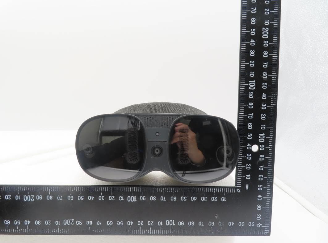
NM82QBB100
Jan 08, 2023Headset
Equipment Class
DTS - Digital Transmission System