NM8PJ40110SMARTPHONE
HTC Corporation
Click to zoom
Application Details
- Equipment Class
- DTS - Digital Transmission System
- Date of Grant
- Mar 11, 2012
- Application Purpose
- Original Equipment
- Date of Application
- Mar 11, 2012
- Equipment Note
- SMARTPHONE
- Frequency Range
- 2402.00000000 - 2480.00000000
- Company
- HTC Corporation
- Country
- Taiwan
Documents & Files
Document Text
Text extracted from the exhibit documents filed with the FCC. Open a document above to read the original.
Users Manual
Safety and regulatory guide 2 Safety and regulatory guide Please read before proceeding THE BATTERY IS NOT FULLY CHARGED WHEN YOU TAKE THE DEVICE OUT OF THE BOX. YOUR WARRANTY IS INVALIDATED IF YOU DISASSEMBLE OR ATTEMPT TO DISASSEMBLE THE DEVICE. Privacy restrictions Some countries require full disclosure of recorded telephone conversations, and stipulate that you must inform the person with whom you are speaking that the conversation is being recorded. Always obey the relevant laws and regulations of your country when using the recording feature of your phone. Disclaimers ANY WEATHER, STOCK, OR OTHER INFORMATION, DATA, OR DOCUMENTATION (“ACCESSED INFORMATION”) ARE PROVIDED “AS IS” AND WITHOUT ANY WARRANTY OR ANY TECHNICAL SUPPORT. TO THE MAXIMUM EXTENT PERMITTED BY APPLICABLE LAW, HTC AND ITS AFFILIATES expressly disclaim any and all representations and warranties, arising by law or otherwise, related to the Accessed Information, including without limitation any express or implied representation or warranty of merchantability, fitness for a particular purpose, non-infringement, quality, accuracy, completeness, effectiveness, reliability, or usefulness. Without limiting the foregoing, it is further understood that HTC and its Affiliates are not responsible for any use of the Accessed Information or the results arising from such use, and that you use such information at your own risk. Safety and regulatory guide 3 Limitation of damages TO THE MAXIMUM EXTENT PERMITTED BY APPLICABLE LAW, IN NO EVENT SHALL HTC OR ITS AFFILIATES BE LIABLE TO YOU, ANY USER, OR THIRD PARTY FOR ANY INDIRECT, SPECIAL, CONSEQUENTIAL, INCIDENTAL OR PUNITIVE DAMAGES OF ANY KIND, ARISING IN CONTRACT, TORT, OR OTHERWISE, INCLUDING, BUT NOT LIMITED TO, INJURY, LOSS OF REVENUE, LOSS OF GOODWILL, LOSS OF BUSINESS OPPORTUNITY, LOSS OF DATA, AND/OR LOSS OF PROFITS, REGARDLESS OF THE FORESEEABILITY THEREOF OR WHETHER HTC OR ITS AFFILIATES HAVE BEEN ADVISED OF THE POSSIBILITY OF SUCH DAMAGES. AND IN NO EVENT SHALL THE TOTAL LIABILITY OF HTC OR ITS AFFILIATES EXCEED THE AMOUNT RECEIVED FROM YOU, REGARDLESS OF THE LEGAL THEORY UNDER WHICH THE CAUSE OF ACTION IS BROUGHT. THE FOREGOING DOES NOT AFFECT ANY STATUTORY RIGHTS WHICH MAY NOT BE DISCLAIMED. Important health information and safety precautions When using this product, the safety precautions below must be taken to avoid possible legal liabilities and damages. Retain and follow all product safety and operating instructions. Observe all warnings in the operating instructions on the product. To reduce the risk of bodily injury, electric shock, fire, and damage to the equipment, observe the following precautions. Electrical safety This product is intended for use when supplied with power from the designated battery or power supply unit. Other usage may be dangerous and will invalidate any approval given to this product. Safety precautions for proper grounding installation CAUTION: Connecting to improperly grounded equipment can result in an electric shock to your device. This product is equipped with a USB Cable for connecting with desktop or notebook computer. Be sure your computer is properly grounded (earthed) before connecting this product to the computer. The power supply cord of a desktop or notebook computer has an equipment-grounding conductor and a grounding plug. The plug must be plugged into an appropriate 4 Safety and regulatory guide outlet which is properly installed and grounded in accordance with all local codes and ordinances. Safety precautions for power supply unit Use the correct external power source A product should be operated only from the type of power source indicated on the electrical ratings label. If you are not sure of the type of power source required, consult your authorized service provider or local power company. For a product that operates from battery power or other sources, refer to the operating instructions that are included with the product. This product should be operated only with the following designated power supply unit(s). AC adapter: HTC, Model TC U250 Handle battery packs carefully This product contains a Lithium-ion polymer or Lithium-ion battery. There is a risk of fire and burns if the battery pack is handled improperly. Do not attempt to open or service the battery pack. Do not disassemble, crush, puncture, short external contacts or circuits, dispose of in fire or water, or expose a battery pack to temperatures higher than 60 ̊C (140 ̊F). WARNING: To reduce risk of fire or burns, do not disassemble, crush, puncture, short external contacts, expose to temperature above 60° C (140° F), or dispose of in fire or water. Recycle or dispose of used batteries according to the local regulations or reference guide supplied with your product. Take extra precautions y Keep the device dry and away from water or any liquid as it may cause a short circuit. y The phone should only be connected to products that bear the USB-IF logo or have completed the USB-IF compliance program. y Only use the battery with a charging system that has been qualified with the system per this standard, IEEE-Std-1725. Safety and regulatory guide 5 Use of an unqualified battery or charger may present a risk of fire, explosion, leakage or other hazard. y Avoid dropping the device. If the device is dropped, especially on a hard surface, and the user suspects damage, take it to a service center for inspection. y If the battery leaks: y Do not allow the leaking fluid to come in contact with skin or clothing. If already in contact, flush the affected area immediately with clean water and seek medical advice. y Do not allow the leaking fluid to come in contact with eyes. If already in contact, DO NOT rub; rinse with clean water immediately and seek medical advice. y Take extra precautions to keep a leaking battery away from fire as there is a danger of ignition or explosion. Safety precautions for direct sunlight Keep this product away from excessive moisture a…
Text truncated - open the document above for the full version.
Users Manual
User guide 20120118_For Certification Only 20120118_For Certification Only 20120118_For Certification Only 20120118_For Certification Only 20120118_For Certification Only 2 Getting started Getting started Front panel 1. BACK 2. HOME 3. Recent Apps 4. VOLUME UP / VOLUME DOWN 5. Proximity sensor 6. Front camera 7. POWER 8. 3.5mm headset jack 9. Notification LED 10. USB connector Top panel 1. Microphone 2. POWER 3. 3.5mm headset jack 2 1 3 20120118_For Certification Only 20120118_For Certification Only 20120118_For Certification Only 20120118_For Certification Only 20120118_For Certification Only 3 Getting started Right panel 1. VOLUME UP 2. VOLUME DOWN Left panel 1. USB connector 1 2 1 20120118_For Certification Only 20120118_For Certification Only 20120118_For Certification Only 20120118_For Certification Only 20120118_For Certification Only 4 Getting started Back panel 1. 8 megapixel camera 2. LED flash 3. Back cover 4. Speaker Status and notifications Status icons Here’s what each icon means: Signal strengthBattery is full GPRS connectedBattery is charging GPRS in useBattery is low (20% remaining) EDGE connectedBattery is very low (10% remaining) EDGE in useSilent mode 3G connectedVibrate mode 2 4 3 1 20120118_For Certification Only 20120118_For Certification Only 20120118_For Certification Only 20120118_For Certification Only 20120118_For Certification Only 5 Getting started 3G in useMicrophone is mute HSDPA connectedSpeakerphone is on HSDPA in use Wired microphone headset connected RoamingWired headset connected No signalBluetooth is on No SIM card installedConnected to a Bluetooth device Connected to a Wi-Fi networkAirplane mode Data synchronizingGPS is on Network sharing is onAlarm is set Notification icons Notification icons on the status bar make it easy for you to keep on top of your messages, calendar events, and alarms. Here’s what each one means: New Gmail messageCall in progress New Microsoft Exchange ActiveSync or POP3/IMAP email Missed call Problem with email deliveryCall on hold New SMS/MMSCall forwarding on Problem with SMS/MMS delivery Message forwarding on New Google Talk instant message Your phone is connected to a computer via USB cable New voicemail Wi-Fi is on and wireless networks are available Upcoming eventPortable Wi-Fi Hotspot is on 20120118_For Certification Only 20120118_For Certification Only 20120118_For Certification Only 20120118_For Certification Only 20120118_For Certification Only 6 Getting started New updates from your social networks Uploading data (animated) Matched contacts suggestionDownloading data (animated) Bluetooth pairing requestWaiting to upload Software update available Downloaded Android Market app installed successfully Song is playing Update available for an app downloaded from Android Market FM Radio app in use Storage card is safe to remove or storage card is being prepared Voice recording is onNo storage card installed More (not displayed) notifications Storage card is low on free space General notification Notification LED The notification LED shows a: Solid green light when you phone is connected to the power adapter or a computer and the battery is fully charged. Flashing green light when you have a pending notification. Solid orange light when the battery is being charged. Flashing red light when the battery level reaches very low. 20120118_For Certification Only 20120118_For Certification Only 20120118_For Certification Only 20120118_For Certification Only 20120118_For Certification Only 7 Getting started Notifications panel When you get a new notification, you can open the Notifications panel to see the message, reminder or event notification. The Notifications panel lets you quickly switch between recently-opened apps, and also lets you easily turn on settings such as Wi-Fi and Bluetooth. To open the Notifications panel, press and hold the status bar, then slide your finger downward. If you have several notifications, you can scroll down the screen to see them all. 20120118_For Certification Only 20120118_For Certification Only 20120118_For Certification Only 20120118_For Certification Only 20120118_For Certification Only
External Photos
Page 1 CONSTRUCTION PHOTOS OF EUT The EUT has following accessories. NO. PRODUCT BRAND MODEL DESCRIPTION 1 Power Adapter 1 PHIHONG TC X250(X=U, B) TC B270 I/P: 100-240Vac, 200mA O/P: 5Vdc, 1A 2 Power Adapter 2 DELTA TC X250(X=U, B) TC B270 I/P: 100-240Vac, 200mA O/P: 5Vdc, 1A 3 Battery 1 ATL BJ40100 Rating: 3.7Vdc, 1650mAh 4 Battery 2 WTE BJ40100 Rating: 3.7Vdc, 1650mAh 5 Earphone 1 MERRY HS S250 - 6 Earphone 2 Cotron HS S250 - 7 USB Cable 1 Foxlink DC M600 - 8 USB Cable 2 Coxoc DC M600 - 9 USB Cable 3 FOXCONN DC M600 - 10 LCM Samsung AMS429QC14 11 Photo Camera Liteon 11P1BEA805A 12 Video Camera Liteon 10P1BF008A - Page 2 Page 3 Page 4 Page 5 Page 6 Page 7 Page 8
ID Label/Location Info
FCC ID: NM8PJ40110 Label and label location Back of cell phone Label location
Internal Photos
Page 9 Page 10 Page 11 Page 12 Page 13 Page 14 Page 15 Page 16 Page 17 Page 18 Page 19
RF Exposure Info
FCC/IC SAR Test Report Report Format Version 4.1.0 Page No. : 1 of 29 Report No. : SA120118C07 Issued Date : Feb. 20, 2012 Revision : R01 FCC/IC SAR Test Report Report No. : SA120118C07 Applicant : HTC Corporation Address : 23, XINGHUA RD., TAOYUAN 330, TAIWAN, R.O.C. Product : Smartphone FCC ID : NM8PJ40110 IC : 4115B-PJ40110 Brand : HTC Model No. : PJ40110 Standards : FCC 47 CFR Part 2 (2.1093) / IEEE C95.1:1991 / IEEE 1528:2003 FCC OET BULLETIN 65 SUPPLEMENT C (EDITION 01-01) / IC RSS-102 ISSUE 4:2010 KDB 248227 D01 v01r02 / KDB 648474 D01 v01r05 / KDB 941225 D01 v02 KDB 941225 D03 v01 / KDB 941225 D06 v01 Date of Testing : Jan. 25, 2012 ~ Feb. 14, 2012 CERTIFICATION: The above equipment have been tested by Bureau Veritas Consumer Products Services (H.K.) Ltd., Taoyuan Branch - Taiwan HwaYa Lab, and found compliance with the requirement of the above standards. The test record, data evaluation & Equipment Under Test (EUT) configurations represented herein are true and accurate accounts of the measurements of the sample’s SAR characteristics under the conditions specified in this report. This test report consists of 29 pages in total except Appendix. It may be duplicated completely for legal use with the approval of the applicant. It should not be reproduced except in full, without the written approval of our laboratory. The client should not use it to claim product certification, approval, or endorsement by TAF or any government agency. The test results in the report only apply to the tested sample. Prepared By : Pettie Chen / Specialist Approved By : Roy Wu / Manager FCC/IC SAR Test Report Report Format Version 4.1.0 Page No. : 2 of 29 Report No. : SA120118C07 Issued Date : Feb. 20, 2012 Revision : R01 Table of Contents Release Control Record ............................................................................................................................................................... 3 1. Summary of Maximum SAR Value ....................................................................................................................................... 4 2. Description of Equipment Under Test ................................................................................................................................. 5 3. SAR Measurement System ................................................................................................................................................... 7 3.1 Definition of Specific Absorption Rate (SAR) ................................................................................................................ 7 3.2 SPEAG DASY System ................................................................................................................................................. 7 3.2.1 Robot .................................................................................................................................................................. 8 3.2.2 Probes ................................................................................................................................................................ 9 3.2.3 Data Acquisition Electronics (DAE) .................................................................................................................... 9 3.2.4 Phantoms ......................................................................................................................................................... 10 3.2.5 Device Holder ................................................................................................................................................... 11 3.2.6 System Validation Dipoles ................................................................................................................................ 11 3.2.7 Tissue Simulating Liquids ................................................................................................................................. 12 3.3 SAR System Verification ............................................................................................................................................ 13 3.4 SAR Measurement Procedure ................................................................................................................................... 14 3.4.1 Area & Zoom Scan Procedure ......................................................................................................................... 14 3.4.2 Volume Scan Procedure ................................................................................................................................... 14 3.4.3 Power Drift Monitoring ...................................................................................................................................... 14 3.4.4 Spatial Peak SAR Evaluation ........................................................................................................................... 15 3.4.5 SAR Averaged Methods ................................................................................................................................... 15 4. SAR Measurement Evaluation ............................................................................................................................................ 16 4.1 EUT Configuration and Setting ................................................................................................................................... 16 4.2 EUT Testing Position .................................................................................................................................................. 16 4.3 Tissue Verification ...................................................................................................................................................... 18 4.4 System Verification ..................................................................................................................................................... 19 4.5 C…
Text truncated - open the document above for the full version.
Test Report
Report No.: RF120118C07-1 R1 1 Report Format Version 4.2.0 Cancels and replaces the report No.: RF120118C07-1 dated Feb. 17, 2012 FCC TEST REPORT (BLUETOOTH) REPORT NO.: RF120118C07-1 R1 MODEL NO.: PJ40110 FCC ID: NM8PJ40110 RECEIVED: Jan. 18, 2012 TESTED: Jan. 19 ~ Feb. 14, 2012 (for original data) Mar. 03, 2012 (for new data) ISSUED: Mar. 05, 2012 APPLICANT: HTC Corporation ADDRESS: 23, Xinghua Rd., Taoyuan 330, Taiwan, R.O.C. ISSUED BY: Bureau Veritas Consumer Products Services (H.K.) Ltd., Taoyuan Branch LAB ADDRESS: No. 47, 14th Ling, Chia Pau Vil., Lin Kou Dist., New Taipei City, Taiwan ( R.O.C ) TEST LOCATION: No. 19, Hwa Ya 2nd Rd, Wen Hwa Tsuen, Kwei Shan Hsiang, Taoyuan Hsien 333, Taiwan, R.O.C. This test report consists of 96 pages in total. It may be duplicated completely for legal use with the approval of the applicant. It should not be reproduced except in full, without the written approval of our laboratory. The client should not use it to claim product certification, approval, or endorsement by TAF or any government agency. The test results in the report only apply to the tested sample. Report No.: RF120118C07-1 R1 2 Report Format Version 4.2.0 Cancels and replaces the report No.: RF120118C07-1 dated Feb. 17, 2012 Table of Contents RELEASE CONTROL RECORD..........................................................................................5 1. CERTIFICATION.......................................................................................................6 2. SUMMARY OF TEST RESULTS ..............................................................................7 2.1 MEASUREMENT UNCERTAINTY ...........................................................................8 3. GENERAL INFORMATION .......................................................................................9 3.1 GENERAL DESCRIPTION OF EUT.........................................................................9 3.2 DESCRIPTION OF TEST MODES.........................................................................10 3.2.1 CONFIGURATION OF SYSTEM UNDER TEST .................................................... 11 3.2.2 TEST MODE APPLICABILITY AND TESTED CHANNEL DETAIL ......................... 12 3.3 GENERAL DESCRIPTION OF APPLIED STANDARDS ........................................15 3.4 DESCRIPTION OF SUPPORT UNITS ...................................................................15 4. TEST TYPES AND RESULTS (FOR BLUETOOTH EDR)......................................16 4.1 RADIATED EMISSION AND BANDEDGE MEASUREMENT.................................16 4.1.1 LIMITS OF RADIATED EMISSION AND BANDEDGE MEASUREMENT .............. 16 4.1.2 TEST INSTRUMENTS ........................................................................................... 17 4.1.3 TEST PROCEDURES ............................................................................................ 18 4.1.4 DEVIATION FROM TEST STANDARD .................................................................. 18 4.1.5 TEST SETUP ......................................................................................................... 19 4.1.6 EUT OPERATING CONDITIONS ........................................................................... 19 4.1.7 TEST RESULTS ..................................................................................................... 20 4.2 CONDUCTED EMISSION MEASUREMENT .........................................................28 4.2.1 LIMITS OF CONDUCTED EMISSION MEASUREMENT....................................... 28 4.2.2 TEST INSTRUMENTS ........................................................................................... 28 4.2.3 TEST PROCEDURES ............................................................................................ 29 4.2.4 DEVIATION FROM TEST STANDARD .................................................................. 29 4.2.5 TEST SETUP ......................................................................................................... 30 4.2.6 EUT OPERATING CONDITIONS ........................................................................... 30 4.2.7 TEST RESULTS ..................................................................................................... 31 4.3 NUMBER OF HOPPING FREQUENCY USED ......................................................35 4.3.1 LIMIT OF HOPPING FREQUENCY USED ............................................................ 35 4.3.2 TEST SETUP ......................................................................................................... 35 4.3.3 TEST INSTRUMENTS ........................................................................................... 35 4.3.4 TEST PROCEDURES ............................................................................................ 35 4.3.5 DEVIATION FROM TEST STANDARD .................................................................. 35 4.3.6 TEST RESULTS ..................................................................................................... 35 4.4 DWELL TIME ON EACH CHANNEL ......................................................................39 4.4.1 LIMIT OF DWELL TIME USED............................................................................... 39 4.4.2 TEST SETUP ......................................................................................................... 39 Report No.: RF120118C07-1 R1 3 Report Format Version 4.2.0 Cancels and replaces the report No.: RF120118C07-1 dated Feb. 17, 2012 4.4.3 TEST INSTRUMENTS ........................................................................................... 39 4.4.4 TEST PROCEDURES ............................................................................................ 39 4.4.5 DEVIATION FROM TEST STANDARD .................................................................. 39 4.4.6 TEST RESULTS ..................................................................................................... 40 4.5 CHANNEL BANDWIDTH.............…
Text truncated - open the document above for the full version.
Test Report
Report No.: RF120118C07 1 Report Format Version 4.2.0 FCC TEST REPORT (WLAN) REPORT NO.: RF120118C07 MODEL NO.: PJ40110 FCC ID: NM8PJ40110 RECEIVED: Jan. 18, 2012 TESTED: Jan. 19 ~ Jan. 31, 2012 ISSUED: Feb. 17, 2012 APPLICANT: HTC Corporation ADDRESS: 23, Xinghua Rd., Taoyuan 330, Taiwan, R.O.C. ISSUED BY: Bureau Veritas Consumer Products Services (H.K.) Ltd., Taoyuan Branch LAB ADDRESS: No. 47, 14th Ling, Chia Pau Vil., Lin Kou Dist., New Taipei City, Taiwan ( R.O.C ) TEST LOCATION: No. 19, Hwa Ya 2nd Rd, Wen Hwa Tsuen, Kwei Shan Hsiang, Taoyuan Hsien 333, Taiwan, R.O.C. This test report consists of 48 pages in total. It may be duplicated completely for legal use with the approval of the applicant. It should not be reproduced except in full, without the written approval of our laboratory. The client should not use it to claim product, certification, approval or endorsement by TAF or any government agency. The test results in the report only apply to the tested sample. Report No.: RF120118C07 2 Report Format Version 4.2.0 TABLE OF CONTENTS RELEASE CONTROL RECORD.............................................................................................. 4 1. CERTIFICATION........................................................................................................... 5 2. SUMMARY OF TEST RESULTS .................................................................................. 6 2.1 MEASUREMENT UNCERTAINTY ............................................................................... 6 3. GENERAL INFORMATION ........................................................................................... 7 3.1 GENERAL DESCRIPTION OF EUT ............................................................................. 7 3.2 DESCRIPTION OF TEST MODES ............................................................................... 8 3.2.1 CONFIGURATION OF SYSTEM UNDER TEST .......................................................... 8 3.2.2 TEST MODE APPLICABILITY AND TESTED CHANNEL DETAIL ............................... 9 3.3 GENERAL DESCRIPTION OF APPLIED STANDARDS ............................................ 11 3.4 DESCRIPTION OF SUPPORT UNITS ....................................................................... 11 4. TEST TYPES AND RESULTS .................................................................................... 12 4.1 RADIATED EMISSION AND BANDEDGE MEASUREMENT..................................... 12 4.1.1 LIMITS OF RADIATED EMISSION AND BANDEDGE MEASUREMENT .................. 12 4.1.2 TEST INSTRUMENTS................................................................................................ 13 4.1.3 TEST PROCEDURES ................................................................................................ 14 4.1.4 DEVIATION FROM TEST STANDARD....................................................................... 14 4.1.5 TEST SETUP.............................................................................................................. 15 4.1.6 EUT OPERATING CONDITIONS ............................................................................... 15 4.1.7 TEST RESULTS ......................................................................................................... 16 4.2 CONDUCTED EMISSION MEASUREMENT ............................................................. 28 4.2.1 LIMITS OF CONDUCTED EMISSION MEASUREMENT........................................... 28 4.2.2 TEST INSTRUMENTS................................................................................................ 28 4.2.3 TEST PROCEDURES ................................................................................................ 29 4.2.4 DEVIATION FROM TEST STANDARD....................................................................... 29 4.2.5 TEST SETUP.............................................................................................................. 30 4.2.6 EUT OPERATING CONDITIONS ............................................................................... 30 4.2.7 TEST RESULTS ......................................................................................................... 31 4.3 6dB BANDWIDTH MEASUREMENT.......................................................................... 35 4.3.1 LIMITS OF 6dB BANDWIDTH MEASUREMENT ....................................................... 35 4.3.2 TEST SETUP.............................................................................................................. 35 4.3.3 TEST INSTRUMENTS................................................................................................ 35 4.3.4 TEST PROCEDURE................................................................................................... 35 4.3.5 DEVIATION FROM TEST STANDARD....................................................................... 35 4.3.6 EUT OPERATING CONDITIONS ............................................................................... 35 4.3.7 TEST RESULTS ......................................................................................................... 36 4.4 CONDUCTED OUTPUT POWER............................................................................... 37 Report No.: RF120118C07 3 Report Format Version 4.2.0 4.4.1 LIMITS OF CONDUCTED OUTPUT POWER MEASUREMENT ............................... 37 4.4.2 TEST SETUP.............................................................................................................. 37 4.4.3 TEST INSTRUMENTS................................................................................................ 37 4.4.4 TEST PROCEDURES ................................................................................................ 37 4.4.5 DEVIATION FROM TEST STANDARD....................................................................... 37 4.4.6 EUT OPERATING CONDITIONS ............................................................................... 37 4.4.7 TEST RESULTS ...................…
Text truncated - open the document above for the full version.
Test Setup Photos
FCC/IC SAR Test Report Report Format Version 4.1.0 Report No. : SA120118C07 Revision : R01 <Photographs of EUT> EUT – Front View EUT – Rear View Earphone 1 Earphone 2 FCC/IC SAR Test Report Report Format Version 4.1.0 Report No. : SA120118C07 Revision : R01 <Photographs of SAR Setup> Right Cheek Right Tilted Left Cheek Left Tilted Front Face of EUT with 1 cm Gap (EUT without Earphone) Rear Face of EUT with 1 cm Gap (EUT without Earphone) FCC/IC SAR Test Report Report Format Version 4.1.0 Report No. : SA120118C07 Revision : R01 Left Side of EUT with 1 cm Gap (EUT without Earphone) Right Side of EUT with 1 cm Gap (EUT without Earphone) Bottom Side of EUT with 1 cm Gap (EUT without Earphone) Top Side of EUT with 1 cm Gap (EUT without Earphone) Rear Face of EUT with 1 cm Gap (EUT with Earphone)
Test Setup Photos
1 PHOTOGRAPHS OF THE TEST CONFIGURATION (For WLAN & Bluetooth) CONDUCTED EMISSION TEST 2 RADIATED EMISSION TEST 3 (For Mobile Phone) (PART 22) RADIATED EMISSION TEST 4 ERP POWER TEST 5 (PART 24) RADIATE…
Text truncated - open the document above for the full version.
Contact Information
Applicant
Sylvia Shen
Test Firm
Bureau Veritas CPS (H.K.) Ltd., Taoyuan BranchRichard Chen
Technical Specifications
| # | Rule Parts | Frequency Range | Power Output |
|---|---|---|---|
| 2 | 15C | 2.40 GHz - 2.48 GHz | 1.00 mW |
Other Applications from HTC Corporation
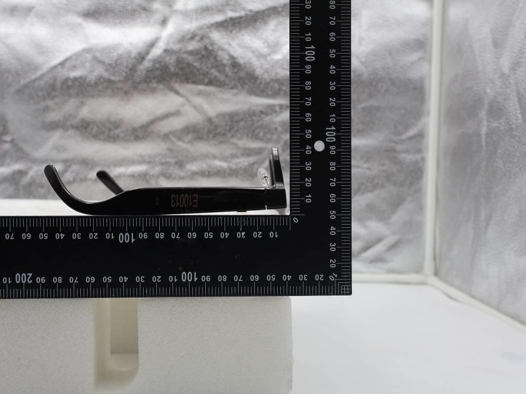
NM82QDJ100
Dec 31, 2025VIVE Headset
Equipment Class
DSS - Part 15 Spread Spectrum TransmitterNM82QD4100
Sep 01, 2024Headset
Equipment Class
6XD - 15E 6 GHz Low Power Indoor Client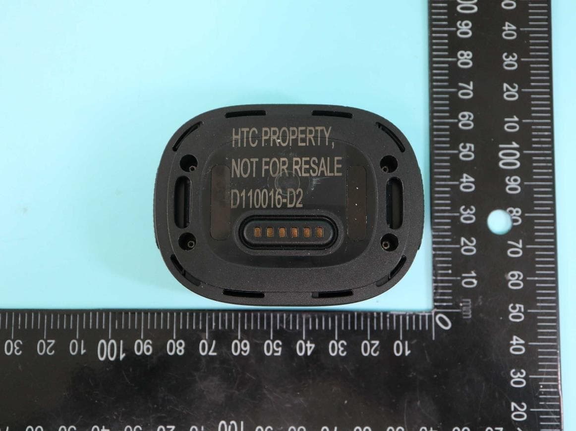
NM82QBP100
May 10, 2023Tracker
Equipment Class
DTS - Digital Transmission System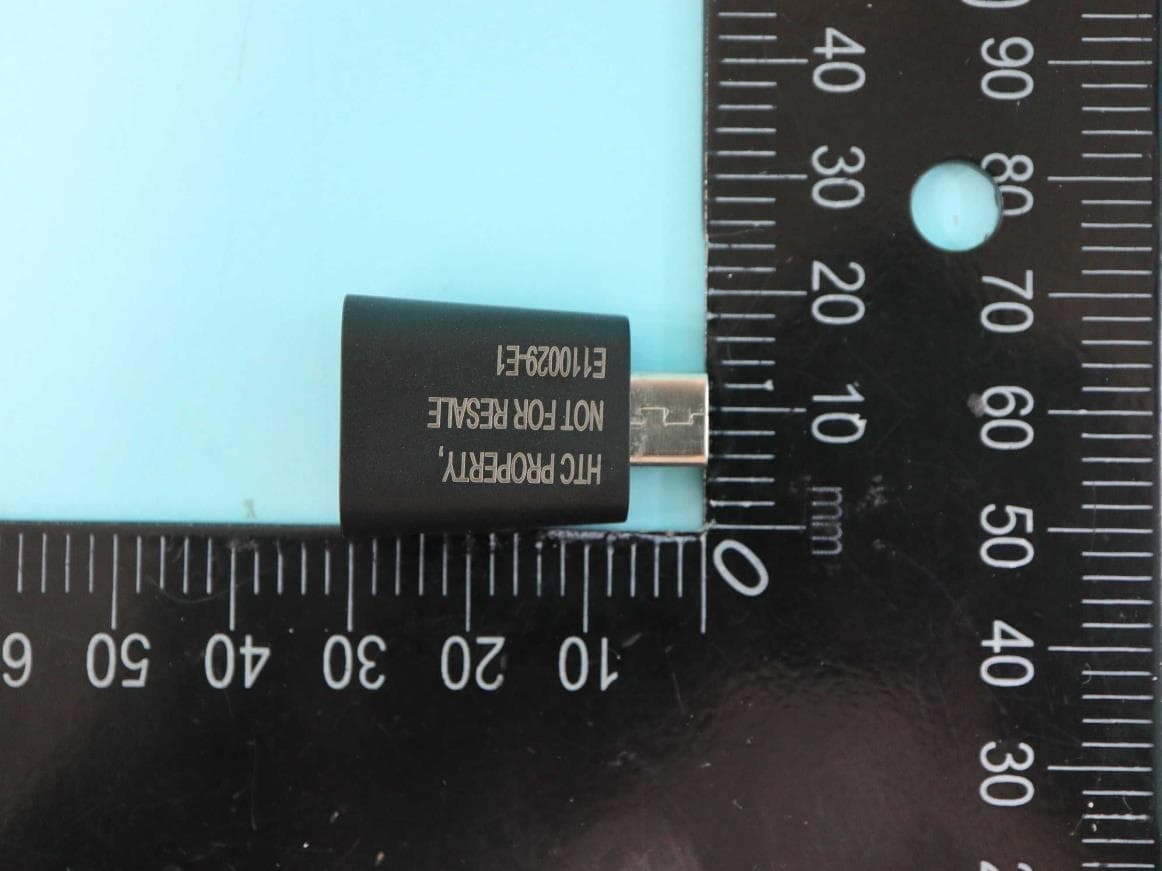
NM82QCD100
May 07, 2023Dongle
Equipment Class
DTS - Digital Transmission System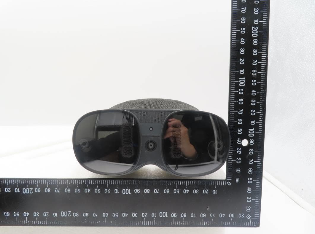
NM82QBB100
Jan 08, 2023Headset
Equipment Class
DTS - Digital Transmission System