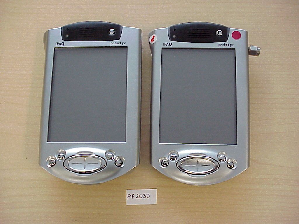
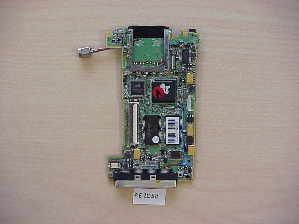
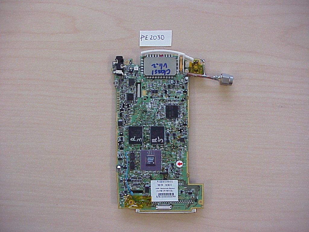
NM8ROSELLAPDA with Bluetooth transceiver
HTC Corporation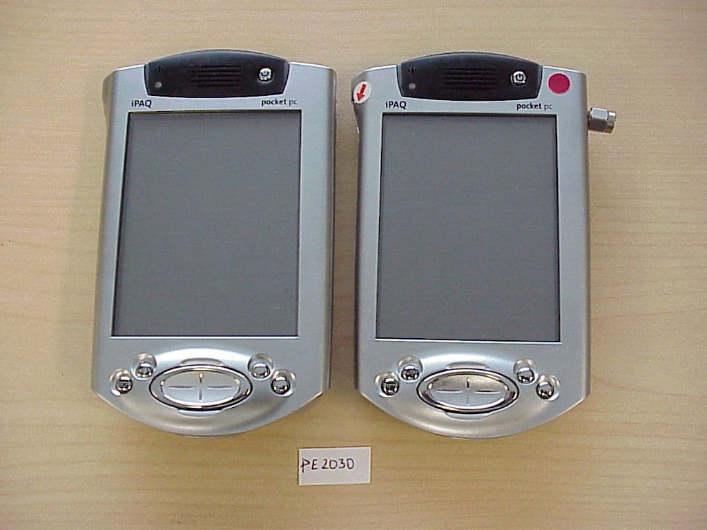
Click to zoom
Application Details
- Equipment Class
- DSS - Part 15 Spread Spectrum Transmitter
- Date of Grant
- Sep 05, 2001
- Application Purpose
- Original Equipment
- Date of Application
- Sep 05, 2001
- Equipment Note
- PDA with Bluetooth transceiver
- Frequency Range
- 2402.00000000 - 2480.00000000
- Company
- HTC Corporation
- Country
- Taiwan
Documents & Files

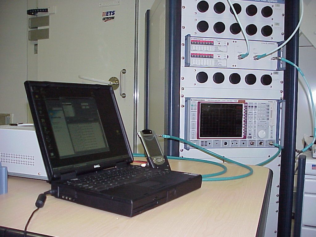
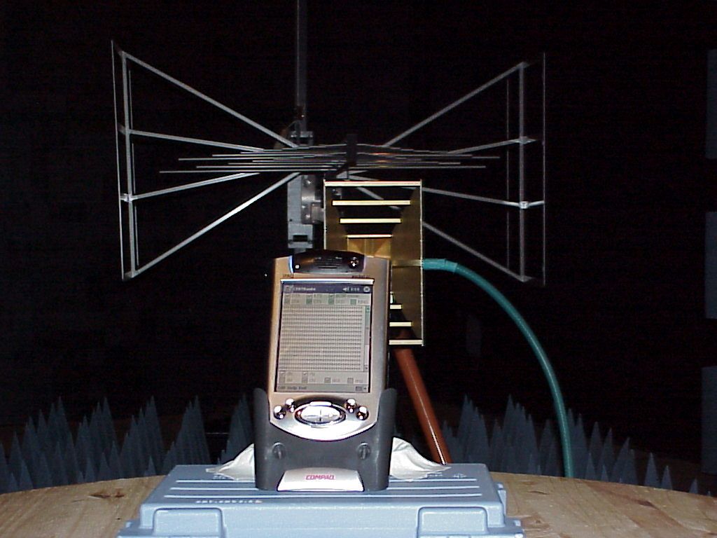
Document Text
Text extracted from the exhibit documents filed with the FCC. Open a document above to read the original.
Users Manual
bC OMPAQ I PAQ POCKET PC H3800 S ERIES G ETTING S TARTED G UIDE Title.fm Page i Thursday, August 16, 2001 1:44 PM ii NOTICEThe information in this document is subject to change without notice.COMPAQ COMPUTER CORPORA-TION SHALL NOT BE LIABLE FOR TECHNICAL OR EDITORIAL ERRORS OR OMISSIONS CON-TAINED HEREIN; NOR FOR INCI-DENTAL OR CONSEQUENTIAL DAMAGES RESULTING FROM THE FURNISHING, PERFORMANCE, OR USE OF THIS MATERIAL.This document contains informa-tion protected by copyright. No part of this document may be photo-copied or reproduced in any form without prior written consent from Compaq Computer Corporation. © 2001 Compaq Computer Corpo-ration. Compaq, the Compaq logo, and iPAQ are trademarks of Compaq Information Technologies Group, L.P. in the US and other countries. Microsoft, MS, ActiveSync, Win-dows, Windows NT, and the Win-dows logo are trademarks of Microsoft Corporation. Intel is a trademark of Intel Corporation. All other product names mentioned herein may be trademarks of their respective companies. Compaq shall not be liable for technical or editorial errors or omissions con-tained herein. The information in this document is provided “as is” without warranty of any kind and is subject to change without notice. The warranties for Compaq prod-ucts are set forth in the express limited warranty statement accom-panying such products. Nothing herein should be construed as con-stituting an additional warranty.Compaq iPAQ Pocket PC H3800 Series Getting Started GuideFirst Edition September 2001 Part Number 254638-001 Legal.fm Page ii Thursday, August 16, 2001 1:45 PM iii Contents Getting Acquainted . . . . . . . . . . . . . . . .1What Is in the Box? . . . . . . . . . . . . . . . . . . . . 1Register . . . . . . . . . . . . . . . . . . . . . . . . . . . . 5Set Up Your Compaq iPAQ Pocket PC . . . . . . . 5Set Up Synchronization . . . . . . . . . . . . . . . . . 8Navigate through the Interface . . . . . . . . . . . 13Enter Information . . . . . . . . . . . . . . . . . . . . . 21Communicating . . . . . . . . . . . . . . . . . .31 Work with Contacts. . . . . . . . . . . . . . . . . . . 31Scheduling . . . . . . . . . . . . . . . . . . . . . . 34Use the Today Screen . . . . . . . . . . . . . . . . . 34Use the Calendar . . . . . . . . . . . . . . . . . . . . . 38Use Tasks . . . . . . . . . . . . . . . . . . . . . . . . . . 40 Using Software . . . . . . . . . . . . . . . . . . 43Use Microsoft Reader . . . . . . . . . . . . . . . . . 43Regulatory Notices . . . . . . . . . . . . . . . 45Federal Communications Commission Notice 45Canadian Notice . . . . . . . . . . . . . . . . . . . . . 46Avis Canadien . . . . . . . . . . . . . . . . . . . . . . 46European Union Notice . . . . . . . . . . . . . . . . 46Battery Warning . . . . . . . . . . . . . . . . . . . . . 47Airline Travel Notice . . . . . . . . . . . . . . . . . . 47Power Cords . . . . . . . . . . . . . . . . . . . . . . . 47Hardware Specifications . . . . . . . . . . 49System Specifications. . . . . . . . . . . . . . . . . 49Physical Specifications . . . . . . . . . . . . . . . . 50Operating Environment . . . . . . . . . . . . . . . . 51 GS 5x3TOC.fm Page iii Thursday, August 16, 2001 1:46 PM iv Routine Care and Battery Guidelines . .52Routine Care . . . . . . . . . . . . . . . . . . . . . . . . 52Battery Guidelines . . . . . . . . . . . . . . . . . . . . 52 GS 5x3TOC.fm Page iv Thursday, August 16, 2001 1:46 PM 1 What Is in the Box? Getting Acquainted To use your Compaq iPAQ ™ Pocket PC H3800 series most effectively, start by learning how to• register your Compaq iPAQ Pocket PC • set up your Compaq iPAQ Pocket PC • set up synchronization• navigate through the interface• enter informationBecause your Compaq iPAQ Pocket PC uses some power to maintain files in RAM and the clock, you need to recharge the battery regularly. Keep the Compaq iPAQ Pocket PC connected to the universal cradle or the AC adapter while you are at your desk. The best policy is to keep the Compaq iPAQ Pocket PC connected to your computer when working at your desk and carry your AC adapter and DC adapter plug with you when traveling.Charge your Compaq iPAQ Pocket PC for three hours before you first use it. CAUTION: Because most of the applications and data you install on your Compaq iPAQ Pocket PC are held in memory, you will need to reinstall them if the battery completely dis- charges. What Is in the Box?Your Compaq iPAQ Pocket PC ships with• the Getting Started Guide• Compaq iPAQ Pocket PC Com- panion CD-ROM– Microsoft® ActiveSync 3.5 software on the Companion CD-ROM – Add-on software and applications – detailed eBook guide, which you can copy to your Compaq iPAQ Pocket PC 01 Getting Acquainted.fm Page 1 Thursday, August 16, 2001 1:46 PM 2 What Is in the Box? – interactive Flash guide available on the CD-ROM – comprehensive printable reference guide • a universal cradle for both USB and serial connections • a protective cover pack•an extra stylus• an AC adapter• a rubber retainer• a DC adapter plug If items are missing, contact Cus-tomer Support at the numbers pro-vided in the Worldwide Telephone Numbers booklet. 01 Getting Acquainted.fm Page 2 Thursday, August 16, 2001 1:46 PM 3 What Is in the Box? Front Panel1 Stylus: push to eject, push to lock 2 Power Indicator: amber flash = charging; amber solid = charged; green = alarm 3 Power Button 4 Speaker: alarms, recordings 5 Color Display 6 Programmable Application Buttons 1-4 (left to right): navigate to applications, default: button 1 is Calendar, button 2 is Contacts, button 3 is Inbox, button 4 is iPAQ Task 7 Navigation Button: scroll through a list 8 Record/Application Button 5 9 Light sensor: adjusts backlight - Stereo Headphone Jack q Active Bluetooth Indicator: flashes when Bluetooth radio is on (Bluetooth models only) w Microphone 01 Getting Acquainted.fm Page 3 Thursday, August 16, 2001 1:46 PM 4 What Is in the Box? Top Panel1 Stereo Headphone Jack 2 Microphone 3 Hidden Infrared Port: beams information with other mo…
Text truncated - open the document above for the full version.
Operational Description
Description of Frequency Hopping System Frequency Bands and Channel Arrangement29 November 199919 BLUETOOTH SPECIFICATION Version 1.0 Bpage 19 of 1082 Radio Specification 2 FREQUENCY BANDS AND CHANNEL ARRANGEMENT The Bluetooth system is operating in the 2.4 GHz ISM (Industrial Scientific Medicine) band. In a vast majority of countries around the world the range of this frequency band is 2400 - 2483.5 MHz. Some countries have however national limitations in the frequency range. In order to comply with these national limitations, special frequency hopping algorithms have been specified for these countries. It should be noted that products implementing the reduced frequency band will not work with products implementing the full band. The products implementing the reduced frequency band must therefore be consid- ered as local versions for a single market. The Bluetooth SIG has launched a campaign to overcome these difficulties and reach total harmonization of the frequency band. Channel spacing is 1 MHz. In order to comply with out-of-band regulations in each country, a guard band is used at the lower and upper band edge. GeographyRegulatory RangeRF Channels USA, Europe and most other countries 1) Note 1. Japan, the MPT announced at the beginning of October 1999 that the Japanese frequency band would be extended to 2400-2483.5 MHz, effective immediately. Testing of devices by TELEC may however need some time to change. The previ- ously specified special frequency-hopping algorithm covering 2471-2497 MHz remains as an option. 2.400-2.4835 GHzf=2402+k MHz, k=0,...,78 Spain 2) Note 2. There is a proposal in Spain to extend the national frequency band to 2403- 2483.5 MHz. The Bluetooth SIG has approached the authorities in Spain to get a full harmonization. The outcome is expected by the beginning of year 2000. 2.445-2.475 GHzf=2449+k MHz, k=0,...,22 France 3) Note 3. The Bluetooth SIG has established good contacts with the French authorities and are closely following the development of harmonization. 2.4465-2.4835 GHzf=2454+k MHz, k=0,...,22 Table 2.1: Operating frequency bands GeographyLower Guard BandUpper Guard Band USA2 MHz3.5 MHz Europe (except Spain and France)2 MHz3.5 MHz Spain4 MHz26 MHz France7.5 MHz7.5 MHz Japan2 MHz2 MHz Table 2.2: Guard Bands Physical Channel29 November 199943 BLUETOOTH SPECIFICATION Version 1.0 Bpage 43 of 1082 Baseband Specification 2 PHYSICAL CHANNEL 2.1 FREQUENCY BAND AND RF CHANNELS Bluetooth operates in the 2.4 GHz ISM band. Although globally available, the exact location and the width of the band may differ by country. In the US and Europe, a band of 83.5 MHz width is available; in this band, 79 RF channels spaced 1 MHz apart are defined. In Japan, Spain, and France, a smaller band is available; in this band, 23 RF channels spaced 1 MHz apart are defined. 2.2 CHANNEL DEFINITION The channel is represented by a pseudo-random hopping sequence hopping through the 79 or 23 RF channels. The hopping sequence is unique for the piconet and is determined by the Bluetooth device address of the master; the phase in the hopping sequence is determined by the Bluetooth clock of the master. The channel is divided into time slots where each slot corresponds to an RF hop frequency. Consecutive hops correspond to different RF hop fre- quencies. The nominal hop rate is 1600 hops/s. All Bluetooth units participating in the piconet are time- and hop-synchronized to the channel. 2.3 TIME SLOTS The channel is divided into time slots, each 625 μs in length. The time slots are numbered according to the Bluetooth clock of the piconet master. The slot numbering ranges from 0 to 2 27 -1 and is cyclic with a cycle length of 2 27 . In the time slots, master and slave can transmit packets. A TDD scheme is used where master and slave alternatively transmit, see Figure 2.1 on page 44. The master shall start its transmission in even- numbered time slots only, and the slave shall start its transmission in odd- numbered time slots only. The packet start shall be aligned with the slot start. Packets transmitted by the master or the slave may extend over up to five time slots. CountryFrequency RangeRF Channels Europe * & USA *. except Spain and France 2400 - 2483.5 MHzf = 2402 + k MHzk= 0,...,78 Japan2471 - 2497 MHzf = 2473 + k MHzk= 0,...,22 Spain2445 - 2475 MHzf = 2449 + k MHzk= 0,...,22 France2446.5 - 2483.5 MHzf = 2454 + k MHzk= 0,...,22 Table 2.1: Available RF channels 4429 November 1999Physical Channel BLUETOOTH SPECIFICATION Version 1.0 Bpage 44 of 1082 Baseband Specification The RF hop frequency shall remain fixed for the duration of the packet. For a single packet, the RF hop frequency to be used is derived from the current Bluetooth clock value. For a multi-slot packet, the RF hop frequency to be used for the entire packet is derived from the Bluetooth clock value in the first slot of the packet. The RF hop frequency in the first slot after a multi-slot packet shall use the frequency as determined by the current Bluetooth clock value. Figure 2.2 on page 44 illustrates the hop definition on single- and multi-slot packets. If a packet occupies more than one time slot, the hop frequency applied shall be the hop frequency as applied in the time slot where the packet transmission was started. Figure 2.1: TDD and timing Figure 2.2: Multi-slot packets 2.4 MODULATION AND BIT RATE The data transmitted has a symbol rate of 1 Ms/s. A Gaussian-shaped, binary FSK modulation is applied with a BT product of 0.5. A binary one is represented by a positive frequency deviation, a binary zero by a negative frequency deviation. The maximum frequency deviation shall be between 140 kHz and 175 kHz. f(k)f(k+1)f(k+2) 625 μs Master Slave f(k) 625 μs f(k+1)f(k+2)f(k+3)f(k+4)f(k+5) f(k)f(k+3)f(k+4)f(k+5) f(k)f(k+5) f(k+6) f(k+6) f(k+6) Hop Selection29 November 1999127 BLUETOOTH SPECIFICATION Version 1.0 Bpage 127 of 1082 Baseband Specification 11 HOP SELECTION In total, 10 types of hopping sequences are defined − f…
Text truncated - open the document above for the full version.
RF Exposure Info
CETECOM Inc. 411 Dixon Landing Road Milpitas, CA 95035 Federal Communication Commission Authorization and Evaluation Division 7435 Oakland Mills Road Columbia, MD 21046 Attention: Reviewing Engineer The pocket PC is a PDA with a built in radio using spread spectrum technique for portable applications for wireless connection to Laptop’s printer’s, other PDA’s etc.. Due to the construction of the PDA the position of the antenna inside (it’s placed on the top of the PDA) a distance under normal operating conditions of more than 1cm can be expected. Due to the low power of the handheld ( less than 2 mW) the MPE limits can be guaranteed as the calculation below shows. Maximum EIRP of the equipment = 1.3 dBm (0.00135W = 1.35mW); equivalent to 20.12 V/m in 1 cm distance Regarding MPE limits, GPUC environment limits maximum exposure to 1 mW/cm 2. The power density is: at 0.01 meters from an antenna S = E 2 /3770=-13 H 2 = 0.107mW/cm 2 < 1 mW/cm 2 Where: S = Power density (mW/cm 2 ) E = electrical field strength (V/m) Calculations are based on standard formula for calculating field strength at a distance and converting power density using free space impedance. Compliance is shown for the built in module, which incorporates the antenna on board of the module even for the distance of 5 cm. This is the distance given by the construction (distance between the module and the outer cover of the Printer. If you should have any questions regarding this submission, please feel free to contact the undersigned. Yours tr ul y, Lothar Schmidt Technical Manager EMC/Radio CETECOM Inc.
Test Report
CETECOM Inc. CETECOM Inc. 411 Dixon Landing Road, Milpitas, CA-95035, USA Phone: +1 408 586 6200 Fax: +1 408 586 6299 www.cetecom.com Issued test report consists of 61 Pages Page 1 (61) Test report no.: 180FCC15.247/2001 FCC Part 15.247 FCC ID: NM8ROSELLA (PE2030) FCC LISTED, REG. NO.: 101450 & RECOGNIZED BY INDUSTRY CANADA IC – 3925 CETECOM Inc. Test report no.:180FCC15.247/2001 Issue date:2000-08-23 Page 2 (63) Table of Contents 1 General information 1.1 Notes 1.2 Testing laboratory 1.3 Details of applicant 1.4 Application details 1.5 Test item 1.6 Test standards 2 Technical test 2.1 Summary of test results 2.2 Test report 1 General information 1.1 Notes The test results of this test report relate exclusively to the test item specified in 1.5. The CETECOM Inc. USA does not assume responsibility for any conclusions and generalisations drawn from the test results with regard to other specimens or samples of the type of the equipment represented by the test item. The test report may only be reproduced or published in full. Reproduction or publication of extracts from the report requires the prior written approval of the CETECOM Inc USA. TEST REPORT PREPARED BY: EMC & Radio Engineer: Harpreet Sidhu 1.2 Testing laboratory CETECOM Inc. 411 Dixon Landing Road, Milpitas, CA-95035, USA Phone: +1 408 586 6200 Fax: +1 408 586 6299 E-mail: [email protected] CETECOM Inc. Test report no.:180FCC15.247/2001 Issue date:2000-08-23 Page 3 (63) Internet: www.cetecom.com 1.3 Details of applicant Name : High Tech Computer Corp. Street : 9F,6-3, Bau-Chian Rd., Hsin Tien City : Taipei 231 Country : Contact : Taiwan Jesse Kuo Telephone : +886 2 8912 4138 ext. 8391 Telefax : +886 2 8912 4136 e-mail : [email protected] 1.4 Application details Date of receipt of application : 2001-08-01 Date of receipt of test item : 2001-08-16 Date of test : 2001-08-16/17 1.5 Test item Manufacturer : applicant Name of EUT : Pocket PC Description : Pocket PC with Bluetooth(TM) function Model No. : PE2030 Serial No. : FCC ID : N/A NM8ROSELLA Additional informations Frequency : 2402 – 2480 MHz Type of modulation : GFSK BT=0.5 Number of channels : 79 Antenna : Internal L Type Antenna Power supply : 100-240 VAC 0.4A 50/60 Hz Output power : 0 dBm Extreme Vol. Limits : Extreme Temp. Limits : 3.8VDC – 4.2VDC 0°C - +60°C H/W & S/W : AX01 & 0.89 1.6 Test standards: FCC Part 15 §15.247 CETECOM Inc. Test report no.:180FCC15.247/2001 Issue date:2000-08-23 Page 4 (63) 2 Technical test 2.1 Summary of test results No deviations from the technical specification(s) were ascertained in the course of the tests performed. Technical responsibility for area of testing : 2001-08-23 EMC & Radio Lothar Schmidt Date Section Name Signature CETECOM Inc. Test report no.:180FCC15.247/2001 Issue date:2000-08-23 Page 5 (63) 2.2 Testreport TEST REPORT Test report no. : 180FCC15.247/2001 FCC ID: NM8ROSELLA (PE2030) CETECOM Inc. Test report no.:180FCC15.247/2001 Issue date:2000-08-23 Page 6 (63) TEST REPORT REFERENCE LIST OF MEASUREMENTS Paragraph PARAMETER TO BE MEASURED PAGE Transmitter parameters § 15.204 Antenna gain 7 § 15.247 (a) Carrier frequency separation 8 § 15.247 (a) Number of hopping channels 9 § 15.247 (a) Time of occupancy (dwell time) 13 § 15.247 (a)(1) Spectrum Bandwith of a FHSS System 16 § 15.247 (b)(2) Maximum peak output power 20 §15.247 Band edge compliance 28 § 15.247 (c)(1) Emission limitations 32 § 15.107/207 AC Line Conducted Emission 45 Receiver parameters § 15.209 Spurious radiations - Radiated 49 Test equipment listing 54 Test Site 55 Photographs of the equipment 57 CETECOM Inc. Test report no.:180FCC15.247/2001 Issue date:2000-08-23 Page 7 (63) CETECOM Inc. Test report no.: 149B FCC/2001 Issue Date: 2001-05-17 Page 8 (63) Antenna Gain SUBCLAUSE § 15.204 The max gain is +0.773dBi (measured effectiv radiated power – measured conducted power with a temporary RF-connector) CETECOM Inc. Test report no.: 149B FCC/2001 Issue Date: 2001-05-17 Page 9 (63) CARRIER FREQUENCY SEPERATION §15.247(a) CETECOM Inc. Test report no.: 149B FCC/2001 Issue Date: 2001-05-17 Page 10 (63) NUMBER OF HOPPING CHANNELS §15.247(a) The number of hopping channels is 79 (see next 4 plots) The right red line corresponds to the left red line from the next plot. Plot 1: CETECOM Inc. Test report no.: 149B FCC/2001 Issue Date: 2001-05-17 Page 11 (63) Plot 2: CETECOM Inc. Test report no.: 149B FCC/2001 Issue Date: 2001-05-17 Page 12 (63) Plot 3: CETECOM Inc. Test report no.: 149B FCC/2001 Issue Date: 2001-05-17 Page 13 (63) Plot 4: CETECOM Inc. Test report no.: 149B FCC/2001 Issue Date: 2001-05-17 Page 14 (63) TIME OF OCCUPANCY (DWELL TIME) FOR DH1 §15.247(a) The system makes worst case 1600 hops per second or 1 time slot has a length of 625μs with 79 channels. A DH1 Packet need 1 time slot for transmitting and 1 time slot for receiving. Then the system makes worst case 800 hops per second with 79 channels. So you have each channel 10.13 times per second and so for 30 seconds you have 303.9 times of appearence . Each Tx-time per appearence is 464.92 μs. So we have 303.9 * 464.92 μs = 141.29 ms per 30 seconds. CETECOM Inc. Test report no.: 149B FCC/2001 Issue Date: 2001-05-17 Page 15 (63) TIME OF OCCUPANCY (DWELL TIME) FOR DH3 §15.247(a) A DH3 Packets need 3 time slots for transmit and 1 for receicing, then the system makes worst case 400 hops per second with 79 channels. So you have each channel 5.1 times per second and so for 30 seconds you have 153 times of appearence . Each Tx-time per appearence is 1.7 ms. So we have 153 * 1.7 ms = 260 ms per 30 seconds. CETECOM Inc. Test report no.: 149B FCC/2001 Issue Date: 2001-05-17 Page 16 (63) TIME OF OCCUPANCY (DWELL TIME) FOR DH5 §15.247(a) At DH5 Packets you need 5 time slots for transmit and 1 for receicing,then the system makes worst case 266,7 hops per second with 79 channels. So you have each channel 3.36 times per second and so for 30 seconds you have 100,8 times of appearence . Each tx-time per appearence …
Text truncated - open the document above for the full version.
Test Report
Processing Gain Description and test results Page 1 of 11 Properties/Title v2 15 February 2001 MEMORANDUM – PROCESSING GAIN REPORT FOR INTEL(R) PERSONAL WIRELESS MODULE Subject: Results of Processing Gain Tests for FCC Qualification 1 INTRODUCTION This memo presents the results of the Processing Gain (PG) tests carried out for FCC qualification of the Intel(R) Personal Wireless Module chip. The FCC states that the PG from a hybrid Bluetooth receiver must be greater than 17 dB when measured in accordance with the Continuous Wave (CW) jamming margin method. Testing of the Intel(R) Personal Wireless Module “B” Bluetooth chip has found the PG due to the DS section to be approximately 5 dB and the PG due to the FH part to be approximately 15 dB. It is therefore concluded that the Intel(R) Personal Wireless Module Bluetooth Chip complies with the FCC PG requirements for radio communication systems. The rest of this paper outlines the PG measurement technique and discusses the test results. Appendix A contains a list of test equipment and Appendix B contains a printout of the measurement results. 2 METHOD 2.1 PG Definition The Processing Gain from a frequency hopping communication system is derived from two parts, the FH section and the DS section. The PG due to FH is given by a simple equation and is constant. However measurement of the PG due to DS is a little more complex. One technique is to use the CW jamming margin method. This method measures PG due to DS using the following algorithm: A CW signal generator is stepped in 50kHz increments across the passband of the system, recording at each point the generator level required to produce the 0.1% Packet Error Rate (PER). This is the jammer level. This level is then referenced to the output power of the intended Bluetooth signal and the Jammer to Signal Ratio JSR is thus calculated. The worst 4 JSR measurements are discarded and the worst remaining JSR is used to calculate the PG due to DS as follows: sysp LJSRSNRG++= min Page 2 of 11 Properties/Title v2 15 February 2001 where G p = the processing gain of the system, SNR = the signal to noise ratio required for 0.1% BER, JSR min = minimum J/S ratio and L sys = system losses. 2.2 PG Measurement Technique Figure 1 provides an overview of the PG measurement technique. The measurement is performed in two parts, measurement of the system SNR and measurement of JSR min . Figure 1: PG Measurement Technique The system SNR is calculated using the following algorithm. Generate Bluetooth PRBS-9 packets using a Bluetooth chip emulator (1) and a Vector Signal Generator (2). Combine this signal with white noise of a constant level, which is generated using a noise source (4) and a CW Signal Generator (3). Then vary the level of the Bluetooth signal until the BER measured by the Bluetooth chip (7) is 0.1%. The resulting SNR is the signal level divided by the Noise level. Page 3 of 11 Properties/Title v2 15 February 2001 The JSR for a given jamming frequency is calculated using the following algorithm. Generate Bluetooth PRBS-9 packets using the Bluetooth chip emulator (1) and the Vector Signal Generator (2). Combine this signal with a constant CW tone at the jamming frequency using a CW Signal Generator (5) and a combiner (6). Then vary the level of the Bluetooth signal until the PER measured by the Casira Bluetooth Module (7) is 0.1%. The resulting JSR is the signal level divided by the jamming level. 3 RESULTS 3.1 Overview The measurements found that the PG due to DS caused by the access code in page and inquiry mode is found to be approximately 5dB when the access code is a relatively random mixture of 1's and 0's. A random access code causes the most Inter Symbol Interference (ISI) and hence the worst PG for a hybrid system. Therefore only the results for this access code are used in the PG calculation. The PG due to FH is given as PG FH = 10 log 10 (number of frequency hops) The number of hops in a Bluetooth system is 32, therefore the PG due to FH is approximately 15 dB. When this is added to the PG due to DS, the total PG for the Bluetooth chip is approximately 20 dB, above the minimum PG requirement for FCC qualification. 3.2 Detailed Results Test Date: 17/11/00 Sample Time: 30 seconds Access Code: c6967e Signal Frequency: 2.432GHz Receiver Sensitivity: -88.7 dBm Jammer Signal Level: -85.7 dBm Measured SNR: 18.8dB System Losses: 2dB To calculate processing gain, ignore the worst 20% of data points and then apply the following formula: Page 4 of 11 Properties/Title v2 15 February 2001 sysp LJSRSNRG++= min Where G p = Processing Gain of the module SNR = signal to noise ratio of the module JS min = minimum J/S ratio after the worst 20% of J/S samples have been discarded L sys = System losses A total of 20 samples were taken by stepping the jamming signal frequency offsets in 50kHz increments over the bandwidth of the receiver. The worst 4 samples were found at –500kHz, -450kHz, -400kHz and 500kHz and were discarded. The remaining minimum J/S ratio was found to be -15.4dB at an offset of +350kHz Thus, the processing gain due to direct sequence spreading in page and inquiry mode is dBG p 4.524.158.18=+−= -500-400-300-200-1000100200300400500 -30 -25 -20 -15 -10 -5 0 5 Jamming Frequency Offset (kHz) J/S (dBs) J/S ratio performance for Processing Gain FCC Testing Page 5 of 11 Properties/Title v2 15 February 2001 APPENDIX A - TEST EQUIPMENT LIST Reference: Instrument Type Name 1 Bluetooth IC Emulator Board N/A 2 Vector Signal Generator IFR2052 3 CW Signal Generator IFR2025 4 White Noise Generator HP33120A 5 RF Mixer M8HC-7 6 RF Combiner 6 dB loss combiner 7 Bluetooth Motherboard and Bluetooth chip Module Bluetooth Development Kit 8 5V, 4A DC Power Supply N/A 9 Spectrum Analyser HP E4405B Page 6 of 11 Properties/Title v2 15 February 2001 APPENDIX B - TEST RESULTS Timestamp: 14:42.43, 16/11/2000 Signal Freq = 2.432 GHz Jammer Level = -85.7 dBm Jammer Offset = -500 kHz Level = -68.7 dBm BER = 0.03% PER = 0.01%…
Text truncated - open the document above for the full version.
Test Report
1680881 Statement The radiated measurements for the PDA Bluetooth enabled were done in all three orthogonal planes. The results documented in the test report represent the worst case values. This is a common procedure for our measurements and we will include this statement in future test reports. Milpitas Sept. 06, 2001 Lothar Schmidt Technical Manger EMC/Bluetooth Competent Body EMC
Contact Information
Applicant
Sylvia Shen
Technical Contact
CETECOM IncLothar Schmidt
[email protected]408-586-6214
411 Dixon Landing Road · Milpitas, California · United States
Non-Technical Contact
CETECOM IncLothar Schmidt
Test Firm
Cetecom Inc.Lothar Schmidt
Technical Specifications
| # | Rule Parts | Frequency Range | Power Output |
|---|---|---|---|
| 1 | 15C | 2.40 GHz - 2.48 GHz | 1.60 mW |
Other Applications from HTC Corporation
NM82QDJ100
Dec 31, 2025VIVE Headset
Equipment Class
DSS - Part 15 Spread Spectrum TransmitterNM82QD4100
Sep 01, 2024Headset
Equipment Class
6XD - 15E 6 GHz Low Power Indoor Client
NM82QBP100
May 10, 2023Tracker
Equipment Class
DTS - Digital Transmission System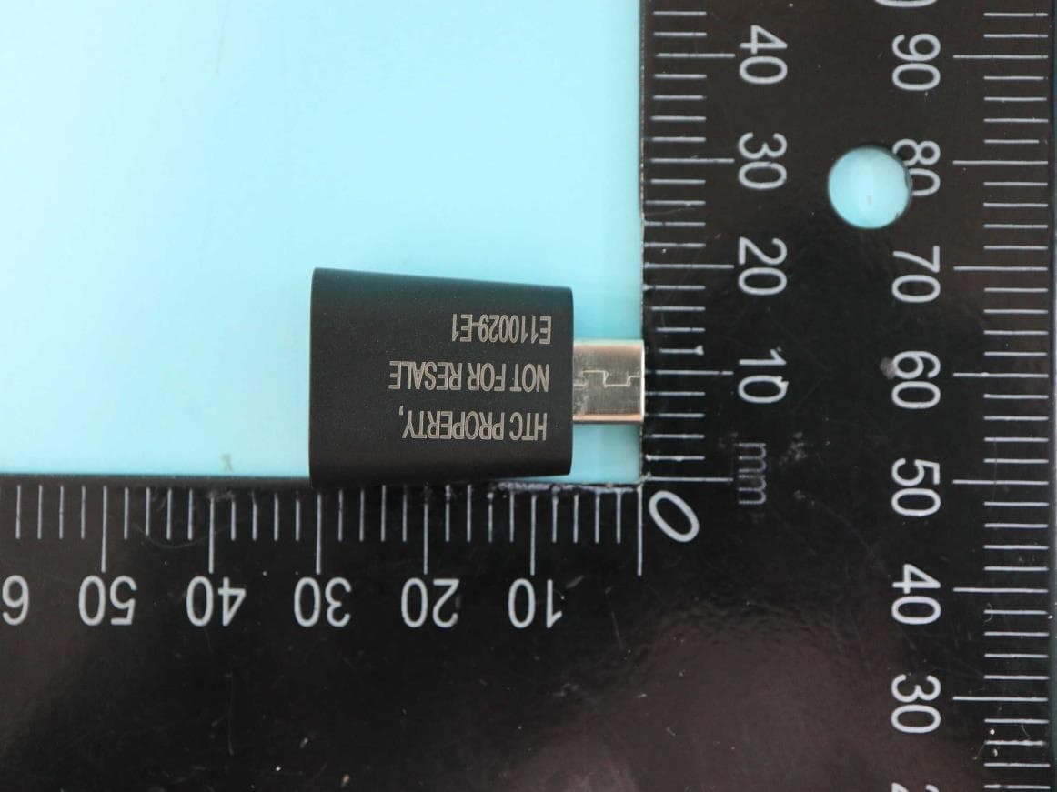
NM82QCD100
May 07, 2023Dongle
Equipment Class
DTS - Digital Transmission System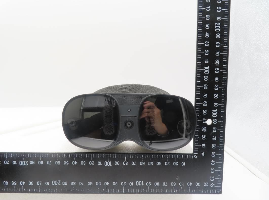
NM82QBB100
Jan 08, 2023Headset
Equipment Class
DTS - Digital Transmission System