NMAEZCOMWL24IPWireless LAN Router
Grayhill Inc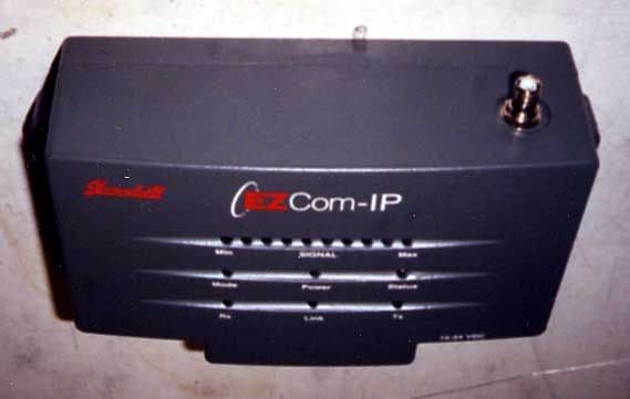
Click to zoom
Application Details
- Equipment Class
- DSS - Part 15 Spread Spectrum Transmitter
- Date of Grant
- Apr 05, 2001
- Application Purpose
- Original Equipment
- Date of Application
- Jan 25, 2001
- Equipment Note
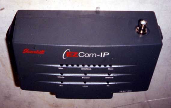
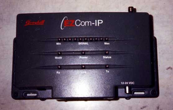
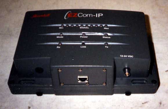
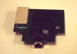
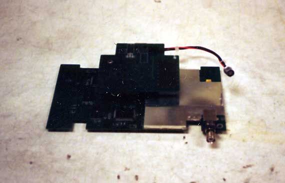
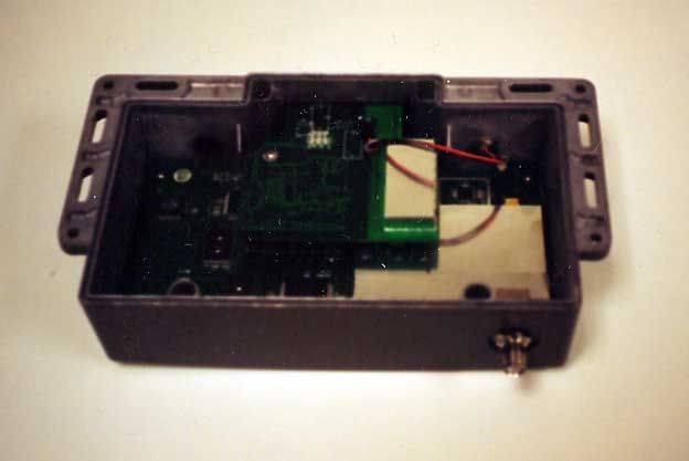
- Wireless LAN Router
- Frequency Range
- 2418.00000000 - 2443.00000000
- Company
- Grayhill Inc
- Country
- United States
Documents & Files
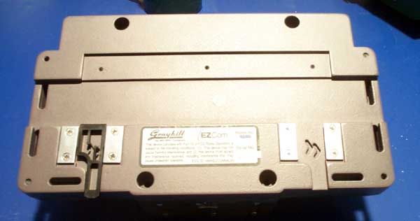
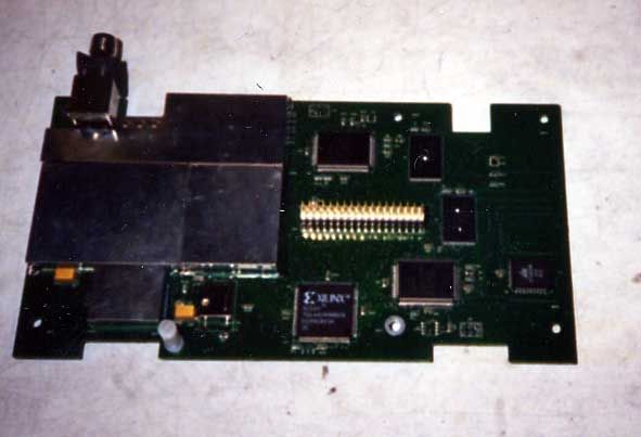
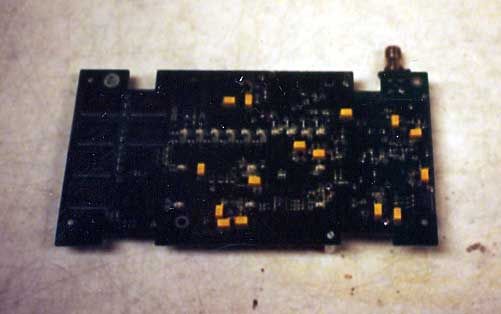
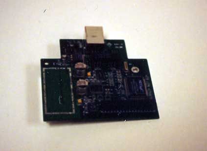
Document Text
Text extracted from the exhibit documents filed with the FCC. Open a document above to read the original.
Users Manual
IP Users Manual Revision A6 Friday, January 26, 2001 Grayhill EZCom IP Users ManualRev A61/26/2001 Page 2 Of 54 Table Of Contents Getting Started.....................................................................................................................4 Initialization.....................................................................................................................4 EZCom-IP Explorer Introduction.................................................................................4 Point-to-Point Link Example........................................................................................6 Windows TCP/IP Set Up...................................................................................................13 Multipoint Store-&-Forward Example........................................................................14 Technical Reference..........................................................................................................18 Introduction...................................................................................................................18 Protocols And Protocol Architecture.............................................................................19 A Simple Model.........................................................................................................20 The TCP/IP Protocol Architecture.............................................................................21 TCP/IP Communications...............................................................................................23 The TCP/IP Protocol Stack.......................................................................................23 Application Layer.......................................................................................................23 Transport Layer.........................................................................................................23 User Datagram Protocol............................................................................................25 Network Layer...........................................................................................................26 Overview of TCP/IP Addresses.................................................................................26 Internet Protocol Routing...........................................................................................28 The ROUTE Utility Program......................................................................................31 Finding Another Machine’s Address.........................................................................32 Ethernet Physical Layer................................................................................................34 MAC Frame...............................................................................................................34 Routing, Putting All of the Pieces Together..............................................................34 Subnetting.....................................................................................................................35 How Do You Subnet?................................................................................................35 Determining Your Addressing Needs....................................................................35 Remembering Binary.................................................................................................35 Defining Your Subnet Mask...................................................................................36 Finding Out How Many Networks, How Many Hosts.............................................37 Subnet IDS.............................................................................................................37 EZCom IP Routing........................................................................................................40 Introduction................................................................................................................40 Indicators and Connectors........................................................................................43 Grayhill EZCom-IP Explorer Program...............................................................................44 Introduction................................................................................................................44 Views.........................................................................................................................44 Menus & Tool Bar......................................................................................................45 Control Tabs..............................................................................................................46 Troubleshooting Guide......................................................................................................50 LED Activity B...............................................................................................................50 No Ethernet Link indicator.............................................................................................50 Link Test Failed.........................................................................................................50 Ping Failed to Respond.............................................................................................51 Ethernet (CSMA/CD).........................................................................................................52 Precursors.................................................................................................................52 Description of CSMA/CD...........................................................................................53 Grayhill EZCom IP Users ManualRev A61/26/2001 Page 3 Of 54 List Of Tables & Figures Table 1, Factory Default Settings.......................................................................................4 Table 2, Point-To-Point Setup Parame…
Text truncated - open the document above for the full version.
Users Manual
NOTE: This equipment has been tested and found to comply with the limits for a Class A digital device, pursuant to part 15 of the FCC Rules. These limits are designed to provide reasonable protection against harmful interference when the equipment is operated in a commercial environment. This equipment generates, uses, and can radiate radio frequency energy and, if not installed and used in accordance with the instruction manual, may cause harmful interference to radio communications. Operation of this equipment in a residential area is likely to cause harmful interference in which case the user will be required to correct the interference at his own expense. (15.105) Modifications to this equipment not expressly approved by Grayhill could void the user's authority to operate the equipment, as well as void any warranty provided by Grayhill. (15.21) Should EZCom-IP be used for fixed point-to-point operation as defined in per FCC rule 15.247.(b).iii the equipment operator, or if the equipment is profesionaly installed, the installer, is responsible for ensuring the system is used exclusevly for point-to-point operations.
Users Manual
72-UM-IP: EZCom-IP User’s Manual • Bulletin #871 2 72-UM-IP FCC NOTICE This equipment has been tested and found to comply with the limits for a Class B digital device, pursuant to Part 15 of the FCC Rules. These limits are designed to provide reasonable protection against harmful interference in a residential installation. This equipment generates, uses, and can radiate radio frequency energy, and, if not installed and used in accordance with the instructions, may cause harmful interference to radio communications. Operation of this equipment in a residential area is likely to cause harmful interference in which case the user will be required to correct the interference at his own expense. (15.105) Modifications to this equipment not expressly approved by Grayhill could void the user's authority to operate the equipment, as well as void any warranty provided by Grayhill. (15.21) Should EZCom-IP be used for fixed point-to-point operation as defined in FCC rule 15.247.(b).iii the equipment operator, or if the equipment is professionally installed, the installer, is responsible for ensuring the system is used exclusively for point-to-point operations. RF EXPOSURE INFORMATION When used in a fixed configuration (the radio and antenna are non-mobile) the antenna should be located at least 2 meters from normal human proximity. If used in a mobile configuration the antenna separation must be at least 20 centimeters.
Attestation Statements
Pursuant to 47 CFR Section 0.457(d) Grayhill Inc. requests that the following sections of the test report for NMAEZCOMWL24IP be withheld from normal public inspection. We consider these items trade secretes and propose that they fall within Section 552(b)(4). The schematics for both printer circuit boards. The active component bill of material. Chris Anderson Grayhill Inc. 561 Hillgrove Ave. PO Box 10373 LaGrange, IL 60525 708-482-2312 voice 708-354-2820 fax [email protected]
Cover Letter(s)
To whom it may concern, Grayhill Inc. of LaGrange IL hereby submits the product model number EZCom-IP for certification of compliance with CFR 47 part 15.247. The intentional radiator spurious emissions, unintentional radiator spurious emissions and conducted spurious emissions tests were preformed at UL labs in Northbrook IL, while the remainder of the tests were performed at Grayhill’s LaGrange location. Per OET Bulletin 65 Supplement C section 3 for 2450MHz radios with 4W or less EIRP EZCom-IP will not exceed MPE limits in normal operation. As the radio is designed for use with outdoor antennas or a unity gain indoor antenna located in excess of 20cm from people no special instructions or warnings are necessary. FCC ID:NMAEZCOMWL24IP GRANTEE:Grayhill Inc. 561 Hillgrove Avenue LaGrange, IL 60525-5997 FRN: 0004277307 TEST SITE:Grayhill Inc.Underwriter’s Laboratories 561 Hillgrove Avenue&333 Pfingsten Rd. LaGrange, IL 60525-5997Northbrook, IL 60062-8863 FINAL TEST DATE:January 21 st 2000 REPORT DATE:September 15 th 2000 TEST ENGINEER:Chris Anderson & Jack Steiner
Cover Letter(s)
We would like to request that the duplicate grantee code at the beginning of our recently filed form 731 number EA99870 be removed from the FCC ID. Thus the amended FCC ID would be NMAEZCOMWL24IP. Chris Anderson Grayhill Inc. 708-482-2312 [email protected]
Cover Letter(s)
To whom it may concern, Grayhill Inc. of LaGrange IL hereby submits the product model number EZCom-IP for certification of compliance with CFR 47 part 15.247. The intentional radiator spurious emissions, unintentional radiator spurious emissions and conducted spurious emissions tests were preformed at UL labs in Northbrook IL, while the remainder of the tests were performed at Grayhill’s LaGrange location. Per OET Bulletin 65 Supplement C section 3 for 2450MHz radios with 4W or less EIRP EZCom-IP will not exceed MPE limits in normal operation. An RF exposure notice however has been included in the manual on page 2. Page 3 of the test report details the 2 antennas sold with the radio and they’re EIRP. FCC ID:NMAEZCOMWL24IP GRANTEE:Grayhill Inc. 561 Hillgrove Avenue LaGrange, IL 60525-5997 FRN: 0004277307 TEST SITE:Grayhill Inc.Underwriter’s Laboratories 561 Hillgrove Avenue&333 Pfingsten Rd. LaGrange, IL 60525-5997Northbrook, IL 60062-8863 FINAL TEST DATE:January 21 st 2000 REPORT DATE:September 15 th 2000 TEST ENGINEER:Chris Anderson & Jack Steiner
Test Report
FCC part 15 testing for Grayhill Inc. Model: EZCom-IP FCC ID:NMAEZCOMWL24IP GRANTEE:Grayhill Inc. 561 Hillgrove Avenue LaGrange, IL 60525-5997 FRN: 0004277307 TEST SITE:Grayhill Inc. 561 Hillgrove Avenue& LaGrange, IL 60525-5997 FINAL TEST DATE:January 21 st 2000 REPORT DATE:September 15 th 2000 TEST ENGINEER:Chris Anderson & Jack Steiner Table of Contents OPERATIONAL DESCRIPTION..........................................................................................................3 LIST OF TESTED ANTENNA CONFIGURATIONS............................................................................3 TEST SUMMARY.................................................................................................................................4 CONDUCTED AC EMISSION SCAN §15.207(A)................................................................................5 6DB BANDWIDTH VERIFICATION §15.247(A)(2)..............................................................................7 CONDUCTED OUTPUT POWER MEASUREMENT §15.247(B)(1)....................................................8 CONDUCTED EMISSIONS FROM THE ANTENNA PORT §15.247(C)..............................................9 PEAK POWER SPECTRAL DENSITY §15.247(D)...........................................................................10 PROCESSING GAIN §15.247(E).......................................................................................................16 RADIATED EMISSIONS FOR A CLASS A DIGITAL DEVICE..........................................................22 RADIATED EMISSIONS IN RESTRICTED BANDS 30MHZ – 25GHZ §15.247(C), 15.209(A).........23 Operational Description The EZCom-IP device is a 2.4GHz direct sequence spread spectrum radio for transport of TCP/IP information packets. Intended use for the device is industrial telemetry. The device performs as an IP router and has a single Ethernet port for network connection. The device examines the destination address of each information packet it sees on either the radio port or the Ethernet port and decides to ignore, respond to or forward the packet. The radio uses PSK modulation with a baseband symbol rate of 1 million symbols per second. To spread the power over frequency an 11 bit pseudo-random code is logical XOR’ed with each symbol. This gives an RF symbol rate of 11 million symbols per second. 11 chips per bit yields a theoretical processing gain of 10*Log(11/1) = 10.4dB. 11 Msps assuming rectangular baseband pulses would yield a bandwidth of approximately 22MHz. The RF section of the device consists of dual conversion super heterodyne transmitter and receiver sections with a PIN diode attenuator for transmit power control. The device runs on 12VDC provided by an external AC-DC power supply running at 110VAC and delivering 12VDC at up to 2.5A. The device is manufactured by Phihong as model # PSA-30U-120P. It is Grayhill’s intent to sell the device only through professional installers, however per 15.203 the antenna connector for the radio is a reverse polarity TNC style connector to ensure use of only approved antenna / cable assemblies. List of Tested Antenna Configurations 1) Maxrad 8dBi omni-directional antenna with 25 ft of Times Microwave LMR-400 coax with a loss of 1.8dB. As the radio transmits 350 mW or 25.4dBm the listed antenna’s gain of 8dBi brings ERP (neglecting coax loss) to 33.4dBm. Test Summary AC Conducted:Pass-15dB avg @.543MHz Neutral 6dB Bandwidth:Pass6dB BW => 7MHz Output Power:PassPeak of 24.0dBm @2.442GHz Conducted Emissions:PassHighest out of band signal was 42dB below fundamental. Spectral Power Density:PassHighest PSD in a 3kHz band averaged over 1 second was 6.72dBm. Processing Gain:Pass81.2% of the data points yield 10dB or better. Res. Band Emissions:PassHighest restricted band emission was 270μV/meter @ 3 meters. Conducted AC Emission Scan §15.207(a) EZ-COMM-IP HOT LINE #2120V/60Hz Marker #Test FrequencyMeter ReadingGain/Loss FactorTransducer FactorFCC Limit (MHz)(dB(uV))(dB)(dB)(dB(uV) 121.9993335.59 avg0.31047.95 EZ-COMM-IP NEUTRAL LINE #1120V/60Hz Marker #Test FrequencyMeter ReadingGain/Loss FactorTransducer FactorFCC Limit (MHz)(dB(uV))(dB)(dB)(dB(uV) 121.9993334.81 avg0.31047.95 20.5295931.23 avg01047.95 Certification and cal info? 6dB Bandwidth Verification §15.247(a)(2) The diamond markers are 7.1MHz apart at 9.3dBm. Taken with an HP8561E RBW=100KHz, span=10MHz, RL=+15dBm Att.= auto. 6dB Bandwidth Verification §15.247(a)(2) 0 2 4 6 8 10 12 14 16 24372438243924402441244224432444244524462447 Freq( MHz) dBm Conducted Output Power Measurement §15.247(b)(1) This test was performed with an HP8900D and HP84811A power sensor with 20dB attenuator. The radio was placed in continuous transmit (100% duty cycle) mode for this test and no duty cycle compensation was used on the power meter. The powers shown include the loss of the attenuator. 2418MHz25.44dBm 2442MHz25.40dBm 2465MHz25.48dBm The radio has 255 levels of power control, with the highest level available to the user factory set with the above power meter to the levels shown. As such the levels above will be the highest levels available from the radio. The user has no means for adjusting the power calibration. Conducted Emissions from the Antenna Port §15.247(c) This test was performed at UL’s Northbrook test facility by UL personnel. The graphs and data are attached. COND SPURIOUS.GIFGraph of conducted emissions from ant. port 1GHz to 25GHz. COND SPURIOUS.TXTData for above. Peak Power Spectral Density §15.247(d) These measurements were taken using an HP8594E spectrum analyzer and HP EMP-441 power meter to ensure the output level was at the same as shown in the conducted output power measurement. For the max, mid and min frequency the first plot shows the 15MHz span centered on the channel. The second graph shows the 30kHz span with 3kHz RBW per 15.247(d). The marker in each graph is at the peak of the graph, with it’s frequency and amplitude shown in the upper right of the plot. #RES BW 10 k…
Text truncated - open the document above for the full version.
Test Report
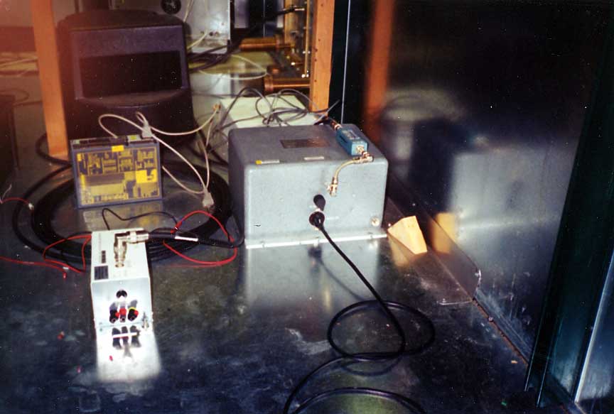
January 23, 2001 Grayhill Inc. Attn:Mr. Rob Haller 561 Hillgrove Avenue LaGrange, IL 60525-5997 UL Reference:File MC1099, Project 00NK37578 Subject:EMC Test and Measurement Report for Model EZCom-IP Dear Mr.Haller: We have provided with this letter your EMC Test Report for the above referenced model. The product was determined to comply with the requirements noted in the report. Please review the attached report and direct any questions or comments to me. Samples were returned following testing. We appreciate your interest in UL’s EMC Services, and encourage you to contact us in the future should you need EMC test services. This closes Project 00NK37578. Best regards,Reviewed by: Bart Mucha (Ext. 41216)Jack Steiner EMC EngineerEngineering Group Leader International EMC ServicesInternational EMC Services UL International EMC Services 333 Pfingsten Road Northbrook, Illinois 60062-2096 (800) 873-8536 Fax No. (847) 272-8864 http://www.ul.com/emc/ FCC ID: NMAEZCOMWL24IP File MC1099 Project 00NK37578Page 1 of 12 UL International EMC Services www.ul.com/emc (800) USE UL EMC EMC – TEST REPORT Issue Date: January 23, 2001 √EMISSIONS IMMUNITY Test Report File No.:MC1099 Project No.:00NK37578 Model / Type:EZCom-IP Kind of Product:2.4GHz Direct Sequence Spread Spectrum Transmitter Applicant:Grayhill Inc. License Holder:Grayhill Inc. Address:561 Hillgrove Avenue :LaGrange, IL 60525-5997 Manufacturer:Same as Applicant : Test Result : COMPLIANT This report without appendices consists of 12 pages. Appendix A contains test photos, Appendix B contains original test data, Appendix C contains sample calculations and Appendix D contains a block diagram of the measurement system. The data contained in this report reflects only the items tested in the configurations and mode of operations described. An attempt has been made to arrange the EUT, with the equipment provided, into a test configuration which maximizes the observed emissions of the EUT while simulating, as close as practical, a typical end-use installation. The photos and data provided in this report document that configuration. Underwriters Laboratories Inc. authorizes the above company to reproduce this report provided it is reproduced in its entirety. Underwriters Laboratories Inc.333 Pfingsten Rd. Northbrook, IL 60062 Fax: (847) 272-8864 FCC ID: NMAEZCOMWL24IP File MC1099 Project 00NK37578Page 2 of 12 UL International EMC Services www.ul.com/emc (800) USE UL EMC REPORT DIRECTORY SECTIONTITLE GENERAL 1.0 General Product Description 1.1 Model Differences 1.2 Environmental Conditions in Test Lab 1.3 Calibration Details of Equipment Used for Measurement 1.4 EUT (Equipment Under Test) Configuration 1.5EUT Operating Mode 1.6Device Modifications EMISSIONS 2.0Emissions Test Regulations Radiated Electric Field Emissions IMMUNITY 3.0Immunity Test Regulations CONCLUSION 4.0General Remarks 4.1Summary APPENDICIES ATest Setups (Photos, Diagrams and Drawings) BTest Data CSample Calculations DBlock Diagram of the Measurement System FCC ID: NMAEZCOMWL24IP File MC1099 Project 00NK37578Page 3 of 12 UL International EMC Services www.ul.com/emc (800) USE UL EMC 1.0GENERAL PRODUCT DESCRIPTION The EUT is a 2.4GHz, direct sequence spread spectrum transmitter. 1.0.1Equipment Mobility: Table-top 1.0.2Test Voltage and Frequency: Voltage (V)Frequency (Hz) 12060 1.1MODEL DIFFERENCES Any other model(s) represented by the models tested in this investigation will be documented by the manufacturer. 1.2ENVIRONMENTAL CONDITIONS IN TEST LAB Temperature:20-25 °C Relative Humidity:30-60% RH Atmospheric Pressure:860-1060 mbar 1.3CALIBRATION OF EQUIPMENT USED FOR MEASUREMENT All test equipment and test accessories are calibrated on a regular basis. The maximum time between calibrations is one year or what is recommended by the manufacturer, whichever is less. All test equipment calibrations are traceable to the National Institute of Standards and Technology (NIST), therefore, all test data recorded in this report is traceable to NIST. FCC ID: NMAEZCOMWL24IP File MC1099 Project 00NK37578Page 4 of 12 UL International EMC Services www.ul.com/emc (800) USE UL EMC 1.4EUT CONFIGURATION(s) See Appendix A for individual set-up configuration(s). In addition to the EUT, the following peripheral devices and/or cables were connected during the measurement: DeviceManufacturerModelSerial #FCC ID EUTGrayhillEZCOM-IPN/ANMAEZCOMWL24IP 8 dBi OMNI Antenna MaxradN/AN/AN/A CableManufacturerLengthType Antenna CableTimes Microwave25 feetLMR-400 1.5 EUT OPERATING MODE(s) The equipment under test was operated during the measurements under the following conditions: 30-1000MHz - Testing was performed with the radio not transmitting and an Axis 2100 digital camera sending streaming image data to the radio as a traffic generator. 1GHz – 25 GHz - Continuous operation, transmitting 350 mW (25.4dBm) at antenna terminals. The listed antenna’s gain is 8dBi resulting in ERP (neglecting coax loss) of 33.4dBm. 1.6DEVICE MODIFICATIONS The following modifications were necessary for compliance: 1. Rated output power was reduced from 440mW to 350mW. 2. Rated high channel was reduced to 2433MHz. These changes will be implemented in firmware in the production radio so users can not go higher in frequency or higher in power. FCC ID: NMAEZCOMWL24IP File MC1099 Project 00NK37578Page 5 of 12 UL International EMC Services www.ul.com/emc (800) USE UL EMC 2.0 EMISSIONS TEST REGULATIONS Emission measurements were performed according to the following regulations: 47 CFR Part 15 Subpart B: 1999 ANSI C63.4 – 1992 Per the manufacturer’s request, only spurious measurements were performed per 15.247(c) of Part 15. The radiated measurements were performed on the highest gain antenna in each antenna family. Since the transmitter operates over a frequency range greater than 10MHz, measurements must be performed on low, mid and high channels per 15.31(m). Average Value of Measured Emissions Per clause 15.35 of CFR 47, Part 15 the measured field…
Text truncated - open the document above for the full version.
Test Report
FCC part 15 testing for Grayhill Inc. Model: EZCom-IP FCC ID:NMAEZCOMWL24IP GRANTEE:Grayhill Inc. 561 Hillgrove Avenue LaGrange, IL 60525-5997 FRN: 0004277307 TEST SITE:Grayhill Inc. 561 Hillgrove Avenue& LaGrange, IL 60525-5997 FINAL TEST DATE:January 21 st 2000 REPORT DATE:September 15 th 2000updated March 20 th 2001. TEST ENGINEER:Chris Anderson & Jack Steiner Table of Contents OPERATIONAL DESCRIPTION..........................................................................................................3 LIST OF TESTED ANTENNA CONFIGURATIONS............................................................................3 TEST SUMMARY.................................................................................................................................4 CONDUCTED AC EMISSION SCAN §15.207(A)................................................................................5 6DB BANDWIDTH VERIFICATION §15.247(A)(2)..............................................................................7 CONDUCTED OUTPUT POWER MEASUREMENT §15.247(B)(1)....................................................8 CONDUCTED EMISSIONS FROM THE ANTENNA PORT §15.247(C)..............................................9 PEAK POWER SPECTRAL DENSITY §15.247(D)...........................................................................10 PROCESSING GAIN §15.247(E).......................................................................................................16 RADIATED EMISSIONS FOR A CLASS A DIGITAL DEVICE.........................................................22 RADIATED EMISSIONS IN RESTRICTED BANDS 30MHZ – 25GHZ §15.247(C), 15.209(A).........23 Operational Description The EZCom-IP device is a 2.4GHz direct sequence spread spectrum radio for transport of TCP/IP information packets. The radio’s intended use for the device is industrial telemetry. The device performs as an IP router and has a single Ethernet port for network connection. The device examines the destination address of each information packet it sees on either the radio port or the Ethernet port and decides to ignore, respond to or forward the packet. The radio uses PSK modulation with a baseband symbol rate of 1 million symbols per second. To spread the power over frequency an 11 bit pseudo-random code is logical XOR’ed with each symbol. This gives an RF symbol rate of 11 million symbols per second. 11 chips per bit yields a theoretical processing gain of 10*Log(11/1) = 10.4dB. 11 Msps assuming rectangular baseband pulses would yield a bandwidth of approximately 22MHz. The RF section of the device consists of dual conversion super heterodyne transmitter and receiver sections with a PIN diode attenuator for transmit power control. The device runs on 12VDC provided by an external AC-DC power supply running at 110VAC and delivering 12VDC at up to 2.5A. The device is manufactured by Phihong as model # PSA-30U-120P. It is Grayhill’s intent to sell the radio and antennas to end users though the use of a professional installer is highly recommended. Per 15.203 the antenna connector for the radio is a reverse polarity TNC style connector to ensure use of only approved antenna / cable assemblies. List of Tested Antenna Configurations 1) Maxrad 8dBi omni-directional monopole antenna with 25 ft of Times Microwave LMR-400 coax with a loss of 1.8dB. 2) Maxrad 2dBi omni-directional monopole attached to the antenna connector of the radio. AntennaIndoor/OutdoorCable lossEIRP 8dBiOutdoor-Fixed1.8dB33.4dBm 2dBiIndoor-Fixed0dB27.4dBm As the radio transmits 350 mW or 25.4dBm the listed antenna’s gain of 8dBi brings ERP (neglecting coax loss) to 33.4dBm. Test Summary AC Conducted:Pass-15dB avg @.543MHz Neutral 6dB Bandwidth:Pass6dB BW => 7MHz Output Power:PassPeak of 25.4dBm @2.442GHz Conducted Emissions:PassHighest out of band signal was 42dB below fundamental. Spectral Power Density:PassHighest PSD in a 3kHz band averaged over 1 second was 6.72dBm. Processing Gain:Pass81.2% of the data points yield 10dB or better. Res. Band Emissions:PassHighest restricted band emission was 270μV/meter @ 3 meters. Conducted AC Emission Scan §15.207(a) EZ-COMM-IP HOT LINE #2120V/60Hz Marker #Test FrequencyMeter ReadingGain/Loss FactorTransducer FactorFCC Limit (MHz)(dB(uV))(dB)(dB)(dB(uV) 121.9993335.59 avg0.31047.95 EZ-COMM-IP NEUTRAL LINE #1120V/60Hz Marker #Test FrequencyMeter ReadingGain/Loss FactorTransducer FactorFCC Limit (MHz)(dB(uV))(dB)(dB)(dB(uV) 121.9993334.81 avg0.31047.95 20.5295931.23 avg01047.95 Certification and cal info? 6dB Bandwidth Verification §15.247(a)(2) The diamond markers are 7.1MHz apart at 9.3dBm. Taken with an HP8561E RBW=100KHz, span=10MHz, RL=+15dBm Att.= auto. 6dB Bandwidth Verification §15.247(a)(2) 0 2 4 6 8 10 12 14 16 24372438243924402441244224432444244524462447 Freq( MHz) dBm Conducted Output Power Measurement §15.247(b)(1) This test was performed with an HP8900D and HP84811A power sensor with 20dB attenuator. The radio was placed in continuous transmit (100% duty cycle) mode for this test and no duty cycle compensation was used on the power meter. The powers shown include the loss of the attenuator. 2418MHz25.44dBm 2442MHz25.40dBm 2465MHz25.48dBm The radio has 255 levels of power control, with the highest level available to the user factory set with the above power meter to the levels shown. As such the levels above will be the highest levels available from the radio. The user has no means for adjusting the power calibration. Conducted Emissions from the Antenna Port §15.247(c) This test was performed at UL’s Northbrook test facility by UL personnel. The graphs and data are attached. COND SPURIOUS.GIFGraph of conducted emissions from ant. port 1GHz to 25GHz. COND SPURIOUS.TXTData for above. Peak Power Spectral Density §15.247(d) These measurements were taken using an HP8594E spectrum analyzer and HP EMP-441 power meter to ensure the output level was at the same as shown in the conducted output power measurement. For the max, mid and min freq…
Text truncated - open the document above for the full version.
Test Report
March 23, 2001 Grayhill Inc. Attn:Mr. Rob Haller 561 Hillgrove Avenue LaGrange, IL 60525-5997 UL Reference:File MC1099, Project 00NK37578 Subject:Revised EMC Test and Measurement Report for Model EZCom-IP Dear Mr.Haller: We have provided with this letter your revised EMC Test Report for the above referenced model. Section 1.6 has been revised to correct a typographical error in the original test report. The rated high channel was reduced to 2443MHz not 2433MHz as originally stated. Please review the attached report and direct an…
Text truncated - open the document above for the full version.
Contact Information
Applicant
Robert W Chiocca(Project Manager)
Test Firm
UL LLCRick Titus
Technical Specifications
| # | Rule Parts | Frequency Range | Power Output | Tolerance |
|---|---|---|---|---|
| 1 | 15C | 2.42 GHz - 2.44 GHz | 350.00 mW | ppm |
Other Applications from Grayhill Inc
NMAM1YY10233
Nov 15, 2007Rugged Industrial PDA
Equipment Class
DTS - Digital Transmission System
NMAM1YY10232
Nov 10, 2007Industrial Handheld Computer
Equipment Class
DSS - Part 15 Spread Spectrum Transmitter
NMAM1YY1021
Dec 12, 2006Rugged Industrial PDA
Equipment Class
DSS - Part 15 Spread Spectrum Transmitter
NMAWM09STDB0001
Nov 08, 2004Data Radio Module
Equipment Class
DSS - Part 15 Spread Spectrum Transmitter
NMAEZCOMLPP
Jun 29, 2003EZCom-LPP
Equipment Class
DTS - Digital Transmission System