NMTAD1122.4GHz USB Dongle
IDT Technology Limited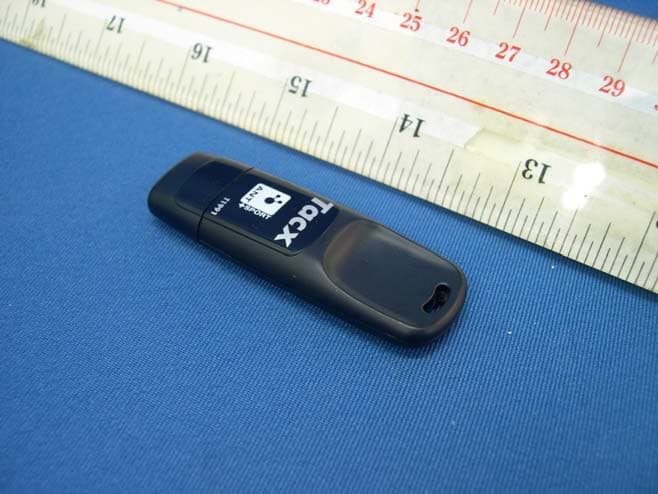
Click to zoom
Application Details
- Equipment Class
- JBP - Part 15 Class B Computing Device Peripheral
- Date of Grant
- Aug 17, 2010
- Application Purpose
- Original Equipment
- Date of Application
- Aug 17, 2010
- Equipment Note
- 2.4GHz USB Dongle
- Company
- IDT Technology Limited
- Country
- Hong Kong
Documents & Files
Document Text
Text extracted from the exhibit documents filed with the FCC. Open a document above to read the original.
Users Manual
Heart Rate Monitor with PC MODEL: SE833L (including SZ912 and AD112) USER MANUAL EN INTRODUCTION Thank you for selecting the Oregon Scientific TM Heart Rate Monitor with PC. Apart from being an advanced heart rate monitor, this watch is also designed with PC download function and Internet connection to allow users to store exercise data and upload to the web for analysis and fitness management. Other functions such as stopwatch with laps and user profiles are available for users to optimize their workout. 2.4GHz-ANT Sports System is used in this watch to achieve reliable transmission linkage with other accessories, such as chest belt (SZ912) and USB dongle (AD112) as well as foot pod and bike pod . IMPORTANT This watch is for sport purposes only and is not meant to replace any medical device. CONTROL BUTTONS 1. - / SP : Toggle options; decrease value; pause/stop during exercise 2. MODE : Toggle modes; return to previous page 3. ST / LAP / + : Toggle options; increase value; mute/un-mute in time display 4. / : Activate backlight; lock / unlock keypad 5. SET : Confirm settings; set alarm on/off in time display DISPLAY 1. : Key to press indicator 2. or : Indicates battery power is low or empty 3. : 12 hour clock 4. : Press the key to exit 5. : Indicates up / down or upper / lower limit 6. : Indicates beep tone is off 7. : Indicates chronometer (stopwatch) is activated 8. : Indicates alarm is on 9. : Indicates heart rate signal is received or heart rate chest belt is paired 10. : Indicates bike and cadence signal is received or bike pod is paired 11. : Resolutions per minute (unit of cadence) 12. : Indicates keypad is locked OPERATING MODES STARTING YOUR WATCH (FIRST TIME) After removing the watch from the package, activate it by pressing and holding MODE until the display is shown. The watch will prompt you to set your profile. The screen below will be shown. 1. Press ST/LAP/+ to select option, then press SET to confirm. 2. Continue setting your profile according to the following order: year of birth, month of birth, day of birth, weight unit and weight value, by pressing the following buttons: • ST/LAP/+ to increase value or select option • -/SP to decrease value • SET to confirm selected option 3. After your profile is set, the screen below will be shown. You can continue to set the watch profile by pressing ST/LAP/+ to select “SET WATCH” option. Refer to “SET WATCH PROFILE” section in this manual. IMPORTANT To ensure accurate calculations with your exercise, you are strongly required to set the watch and user profiles before exercising. NOTE When the watch is left idle for 30 seconds during set up, it will automatically exit and display the time. CONNECTING WITH COMPUTER SOFTWARE Your watch can connect with the computer Application Software via the USB dongle (AD112). 1. Insert the AD112 USB dongle in the computer. 2. Press MODE to select . 3. Press SET to start connecting. 4. If connection is successful, the screen will display “DONE” . If connection fails, the screen will display “FAILED” , press ST/LAP/+ to try again. SETTING UP YOUR WATCH IMPORTANT • To ensure accurate calculations with your exercise, you are strongly required to set the watch and user profiles before exercising. • Remember to set the watch and user profiles after every battery replacement or power reset. NOTE When the watch is left idle for 30 seconds during set up, it will automatically exit and display the time. SET WATCH PROFILE 1. Press MODE to select . 2. Press ST/LAP/+ to select “SET WATCH” . 3. Press SET to enter watch profile setting options. 4. Press ST/LAP/+ or -/SP to select the option to set: set alarm, set time, set date, set unit, set alert * , set view ** . 5. Press SET and start setting the selected option by pressing the following buttons: • ST/LAP/+ to increase value or select option • -/SP to decrease value • SET to confirm selected option * During exercise, when the heart rate or speed rate is out of the target zone, the watch will send out visual and sound alert. You can select to turn on/off the sound alert in the “SET ALERT” option. ** During exercise, the watch will toggle display your exercise information. You can select to turn on/off the toggle display in the “SET VIEW” option. SET USER PROFILE IMPORTANT Reset the user profile if the watch will be used by another person. 1. Press MODE to select . 2. Press ST/LAP/+ to select “SET USER” . 3. Press SET to enter user profile setting options. 4. Follow steps 1 and 2 in “STARTING YOUR WATCH (FIRST TIME)” section in this manual. SET EXERCISE PROFILE IMPORTANT Reset the exercise profile if the watch will be used by another person. You can set exercise profiles for your training and workout. The watch has 3 exercise options: Cardio, Run and Cycling. 1. Press MODE to select . 2. Press ST/LAP/+ to select “SET PROG” . 3. Press SET to enter exercise options. 4. Press ST/LAP/+ or -/SP to select the exercise to set: set run, set cycling, set cardio. 5. Press SET to confirm selection, then continue to set the profile * of the selected exercise by pressing the following buttons: • ST/LAP/+ to increase value or select option • -/SP to decrease value • SET to confirm selected option * The profile setting options are as follows: • Warm up time • Interval training on/off • Number of interval (2-5) • Exercise time for each exercise or interval • Rest time for each interval • Exercise by time • Target heart rate zone (1-5) • Recovery timer on/off PAIRING AND CALIBRATING DEVICE IMPORTANT To ensure accurate calculations with your exercise, you are strongly required to pair and calibrate the watch with the AZ112 heart rate chest belt, foot pod and bike pod before exercise. The bike pod and foot pod should be purchased separately and should be compatible with ANT Sports System. 1. Press MODE to select . 2. Press SET to enter “PAIR DEVICE” . • Press SET to start pairing. OR • If the watch is already paired with device, you can continue to set the paired device by pre…
Text truncated - open the document above for the full version.
Block Diagram
Dynastream Innovations Inc. MultiUSB - FCC ID: O6RUSB-A Power Switch USB to UART Converter 2.4GHz RF Transceiver Chip Antenna 5VDC 5 USB connector 5VDC USB Data 16MHz PRODUCT SPECIFICATION nRF24AP1 Single Chip 2.4 GHz Radio Transceiver with Embedded ANT Protocol Nordic Semiconductor ASA - Vestre Rosten 81, N-7075 Tiller, Norway - Phone +4772898900 - Fax +4772898989 Revision: 1.0 Page 4 of 25 September 2006 1. BLOCK DIAGRAM DVDD VDD=3VVDD=3V XC1 XC2 100Ω+j175Ω IREF VDD_PA=1.8V VSS_PA=0V ANT1 ANT2 22kΩ VSS=0V VSS=0V VDD=3V VSS=0VVSS=0V ANT Protocol Engine PORTSEL 1 Mbps RF Transceiver UART or Synchronous Serial Interface BR2 / SCLK BR1 / SFLOW EXT32K RTS / SEN RXD / SIN TXD / SOUT SUSPEND / SRDY SLEEP / SMSGRDY Timing Figure 1: nRF24AP1 with external components. The “ANT Protocol Engine” shown in Figure 1 is described in the “ANT Message Protocol and Usage” document. Figure 1. Example System Diagram CP2102 3.3 V Voltage Regulator 48 MHz Oscillator IN OUT SUSPEND SUSPEND 11 12 REGIN 7 GND 3 RST 9 D+ 4 D- 5 8 UART RI DCD CTS RTS RXD TXD DSR DTR 2 27 26 25 24 23 2 3 External RS-232 transceiver or UART circuitry (to external circuitry for USB suspend states) VBUS D- D+ GND 4 56 USB CONNECTOR 6 1 VDD VBUS USB Function Controller USB Transceiver 640B TX Buffer 576B RX Buffer 1024B EEPROM VDD D1 D2 D3 1 28
External Photos
INTERTEK TESTING SERVICE Report No.: HK08090972-1 FCC ID: NMTAD112 Equipment Photographs Model: AD112 (External) INTERTEK TESTING SERVICE Report No.: HK08090972-1 FCC ID: NMTAD112 Equipment Photographs Model: AD112 (External)
Internal Photos
INTERTEK TESTING SERVICE Report No.: HK08090972-1 FCC ID: NMTAD112 Equipment Photographs Model: AD112 (Internal) INTERTEK TESTING SERVICE Report No.: HK08090972-1 FCC ID: NMTAD112 Equipment Photographs Model: AD112 (Internal)
Operational Description
FCC ID: NMTAD112 Technical Description (Model: AD112) -CP2102 is USB to UART Converter -U100, nRF24AP1 is 2.4GHz Transceiver -E101 is Chip Antenna The AD112 is a 2.4GHz Wireless Dongle, which is operating at 2405MHz to 2479MHz, in 1MHz intervals. It is operate in conjunction with SZ912, SE833 or other compatible devices. For example, the chest belt is worn on the chest and detects the user’s heart rate. The microcontroller in the chest belt will calculate the heart rate of the user and activate the nRF24AP1 2.4GHz transmitter IC to send encoded RF signal containing the heart rate to this USB dongle and it can store the received heart rate information into PC. The RF output of the nRF24AP1 2.4GHz transmitter IC is connected to the antenna via an Antenna matching network. This network is used to match the impedance of the antenna to the nRF24AP1 2.4GHz transmitter IC and suppress unwanted spurious transmission.
Schematics
123456 A B C D 6 54321 D C B A DATE DRWN. CHKD. PROJ. RLS MGR. BY REV DESCRIPTIONDATE ECO No. REVISIONS This drawing and the specifications contained herein are the property of Garmin Ltd. or its subsidiaries and may not be reproduced or used in whole or in parts as the basis for manufacture or sale of products without written permission. CONFIDENTIAL TOLERANCE UNLESS NOTED OTHERWISE .XX ±.010 .XXX ±.005 HOLES ±.003 METRIC UNITS .X ±..25 .XX ±.13 HOLES ±.08 ENGLISH UNITS ANGLES +/- 0.5º TITLE SCHEM, USB to ANT SIZE B DWG. NO. 014-01339-00 SHT.OF 12 REV C Garmin Ltd. or its subsidiaries c/o Garmin International, Inc. 1200 E. 151st Street Olathe, Kansas 66062 U.S.A SCALE BB 6/8/07 Drafting Location: Dynastream Source Editor: Protel Design changes to be made strictly at Dynastream RF Section 6/11/07 6/12/07 JPM SMP DJW 6/19/07 C104 1nF 10% X7R 50V C103 4.7pF +/-0.25pF 25V JHT/C C107 10nF 5% X7R 25V C110 2.2nF 5% X7R 50V R102 1M C105 NNP C109 33nF 10% X7R 50V R100 22.1K 1% RF_VCC L101 18nH 5% L100 18 nH 5% C111 15pF 5% COG 50V C112 15pF 5% COG 50V BR2/SCLK BR1/SFLOW RXD/SIN SUSPEND/SRDY BR2/SCLK 1 BR1/SFLOW 2 EXT32K 3 RXD/SIN 4 TXD/SOUT 5 SUSPEND/SRDYN 7 SLEEP/SMSGRDYN 6 RTS/SEN 8 DVDD 9 VSS 10 XC2 11 XC1 12 VDD_PA 13 ANT1 14 ANT2 15 VSS_PA 16 VDD 17 VSS 18 IREF 19 VSS 20 VDD 21 VSS 22 PORTSEL 23 VDD 24 U100 AP1 13 Y100 16MHz 9pF TOYOCOM TSX-10A C108 0.4pF +-.1pF 50V C102 NNP 4.7pF +/-0.25pF 25V JHT/C C101 4.7pF +/-0.25pF 25V JHT/C E101 Maglayers 2.45 GHz Chip Antenna, 3.2x1.6x1.2mm L102 3.9 nH +- 0.3 nH TXD/SOUT SLEEP/SMSGRDY RTS/SEN R104 100k R101 100k PORTSEL R103 5.6 nH +-0.3 nH USB_3.3V AProd Rls for Proto Run6/27/0745788 B8/19/2008 Change antenna, update RF tuning component values 55610 C8/20/2008 Center RF match NOTE: R103 is an INDUCTOR 55611 123456 A B C D 6 54321 D C B A TITLE SCHEM, USB to ANT SIZE B DWG. NO. 014-01339-00 SHT.OF 22 REV C Garmin Ltd. or its subsidiaries c/o Garmin International, Inc. 1200 E. 151st Street Olathe, Kansas 66062 U.S.A SCALE USB Section SLEEP/SMSGRDY D-D+VBUSGND 5V 1 D- 2 D+ 3 GND 4 J207 HAND C201 1 uF 10% X7R 6.3V C200 0.1 uF 10% X7R 10V USB_3.3V + C202 22 uF 10% Tant 6.3V 2 41 3 S200 SP0503BAHT RXD TXD RTS/SEN SUSPEND/SRDY RXD/SIN RTS/SEN TXD/SOUT R204 0 ohm RF_VCC RF_VCC R200 NNP R201 10k RF_VCC R202 10k R205 NNP RF_VCC R203 10k R206 NNP PORTSEL BR1/SFLOW BR2/SCLK R200 & R201 set Sync/Async mode (1/0 respectively) R202 & R205 are for Baud Rate (BR1) R203 & R206 are for Baud Rate (BR2) AP1 Rev X BR1 BR2 Baud Rate 0 0 4800 0 1 9200 1 0 50000 1 1 38400 AP1 Rev AX BR1 BR2 Baud Rate 0 0 4800 0 1 19200 1 0 38400 1 1 50000 No Tx Capabilities C203 NNP C204 NNP R207 0 ohm R208 0 ohm TP202 TESTPOINT_SMALL TP203 TESTPOINT_SMALL TP204 TESTPOINT_SMALL TP207 TESTPOINT_SMALL TP200 TESTPOINT_SMALL TP201 TESTPOINT_SMALL C205 1 uF 10% X7R 6.3V J200 MouseBite J203 MouseBite J202 MouseBite PANEL SIDEBOARD SIDE MOUSEBITES AP1 Rev 1 Requires the AP1 to be turned off in suspend mode to meed 500uA current limit AP1 Rev 2 Can use pass through 0ohm resistor To populate the switch, remove R204 and populate Q200 with MMBF2202PT1G and R209 with 1M 0402 R209 NNP 1 32 Q200 NNP R210 4.7 ohm DCD 1 RI 2 GND 3 D+ 4 D- 5 VDD 6 NC 14 VBUS 8 RST 9 NC 10 SUSPEND 11 SUSPEND 12 NC 20 NC 21 NC 15 NC 16 NC 17 NC 18 TXD 26 DSR 27 DTR 28 NC 22 CTS 23 RTS 24 REGIN 7 NC 13 NC 19 RXD 25 GND 0 J201 CP2102
Test Report
Report No.: HK08090972-1 Data Transfer Mode PC’s AC Mains “L” Ctrl No.: N/A PAGE 1 Report No.:HK08090972-1 Scan Settings (1 Range) |--------- Frequencies -----------||----------- Receiver Settings ------------| Start Stop Step IF BW Detector M-Time Atten Preamp OpRge 150k 30M 5k 10k PK+AV 10ms AUTO LN OFF 60dB Final Measurement: x QP / + AV Meas Time: 1 s Subranges: 16 Acc Margin: 20dB Transducer No. Start Stop Name 2 1 9k 30M EW0700 3 9k 30M EW2454 12 9k 30M EW0090 0 10 20 30 40 50 60 70 80 90 dBuV 100 0.15 MHz 30 110 F15Q F15A Report No.: HK08090972-1 Data Transfer Mode PC’s AC Mains “L” Ctrl No.: N/A Report No.:HK08090972-1 Scan Settings (1 Range) |--------- Frequencies -----------||----------- Receiver Settings ------------| Start Stop Step IF BW Detector M-Time Atten Preamp OpRge 150k 30M 5k 10k PK+AV 10ms AUTO LN OFF 60dB Final Measurement Results: Frequency QP Level QP Limit Delta MHz dBuV dBuV dB 0.19000 49.4 64.1 -14.7 0.25500 41.3 61.6 -20.3 0.85500 7.3 56.0 -48.7 Frequency AV Level AV Limit Delta MHz dBuV dBuV dB 0.19000 37.0 54.1 -17.1 0.44500 27.2 46.9 -19.7 14.27500 30.1 50.0 -19.9 * limit exceeded
Test Report
- The test report only allows to be revised within the retention period unless further standard or the requirement was noticed. - This report is for the exclusive use of Intertek's Client and is provided pursuant to the agreement between Intertek and its Client. Intertek's responsibility and liability are limited to the terms and conditions of the agreement. Intertek assumes no liability to any party, other than to the Client in accordance with the agreement, for any loss, expense or damage occasioned by the use of this report. Only the Client is authorized to permit copying or distribution of this report and then only in its entirety. Any use of the Intertek name or one of its marks for the sale or advertisement of the tested material, product or service must first be approved in writing by Intertek. The observations and test results in this report are relevant only to the sample tested. This report by itself does not imply that the material, product, or service is or has ever been under an Intertek certification program. Intertek Testing Services Hong Kong Ltd. 2/F., Garment Centre, 576 Castle Peak Road, Kowloon, Hong Kong. Tel: (852) 2173 8888 Fax: (852) 2785 5487 Website: www.hk.intertek-etlsemko.com TEST REPORT Report No.: HK08090972-1 IDT Technology Limited Application For Certification (Original Grant) (FCC ID: NMTAD112) Transceiver and, Class B Personal Computers and Peripherals Prepared and Checked by: Approved by: Signed On File Mark Cheung Lead Engineer Chan Chi Hung, Terry Senior Lead Engineer Date: August 06, 2010 INTERTEK TESTING SERVICES Report No.: HK08090972-1 FCC ID: NMTAD112 i GENERAL INFORMATION IDT Technology Limited BRAND NAME: Oregon Scientific, MODEL: AD112 FCC ID: NMTAD112 Grantee: IDT Technology Limited Grantee Address: Block C, 9/F., Kaiser Estate, Phase 1, 41 Man Yue Street, Hunghom, Kowloon, Hong Kong. Contact Person: Mr. Thomas Wong Tel: (86) 755-29701087 Fax: (86) 755-29709021 e-mail: [email protected] Manufacturer: N/A Manufacturer Address: N/A Brand Name: Oregon Scientific Model: AD112 Type of EUT: Transceiver Class B Personal Computers and Peripherals Description of EUT: 2.4GHz USB Dongle Serial Number: N/A FCC ID: NMTAD112 Date of Sample Submitted: October 14, 2008 Date of Test: August 02, 2010 Report No.: HK08090972-1 Report Date: August 06, 2010 Environmental Conidtions: Temperature: +10 to 40°C Humidity: 10 to 90% INTERTEK TESTING SERVICES Report No.: HK08090972-1 FCC ID: NMTAD112 ii SUMMARY OF TEST RESULT IDT Technology Limited BRAND NAME: Oregon Scientific, MODEL: AD112 FCC ID: NMTAD112 TEST SPECIFICATION REFERENCE RESULTS Maximum Peak Output Power 15.247(b), (c) / RSS-210 A8.4 N/A Hopping Channel Carrier Frequencies Separation 15.247(e) / RSS-210 A8.1 N/A 20dB Bandwidth of the Hopping Channel 15.247(a) / RSS-210 A8.1 N/A Number of Hopping Frequencies 15.247(e) / RSS-210 A8.1 N/A Average Time of Occupancy of Hopping Frequency 15.247(e) / RSS-210 A8.1 N/A Antenna Conducted Spurious Emissions 15.247(d) / RSS-210 A8.5 N/A Radiated Spurious Emissions 15.247(d) / RSS-210 A8.5 N/A RF Exposure Compliance 15.247(i) / RSS-Gen 5.5 N/A Transmitter Power Line Conducted Emissions 15.207 / RSS-Gen 7.2.2 Pass Transmitter Field Strength 15.227 / RSS-310 3.8 N/A Transmitter Field Strength 15.229 / RSS-210 A2.7 N/A Transmitter Field Strength, Bandwidth and Timing Requirement 15.231(a) / RSS-210 A1.1.1 N/A Transmitter Field Strength, Bandwidth and Timing Requirement 15.231(e) / RSS-210 A1.1.5 N/A Transmitter Field Strength and Bandwidth Requirement 15.239 / RSS-210 A2.8 N/A Transmitter Field Strength and Bandwidth Requirement 15.249 / RSS-210 A2.9 Pass Transmitter Field Strength and Bandwidth Requirement 15.235 / RSS-310 3.9 N/A Digital Device Radiated Emissions 15.109 / ICES-003 Pass Digital Device Conducted Emissions 15.107 / ICES-003 Pass Note: 1. The EUT uses a permanently attached antenna which, in accordance to section 15.203, is considered sufficient to comply with the pervisions of this section. 2. Pursuant to FCC part 15 Section 15.215(c), the 20 dB bandwidth of the emission was contained within the frequency band designated (mentioned as above) which the EUT operated. The effects, if any, from frequency sweeping, frequency hopping, other modulation techniques and frequency stability over excepted variations in temperature and supply voltage were considered. INTERTEK TESTING SERVICES Report No.: HK08090972-1 FCC ID: NMTAD112 iii Table of Contents 1.0 General Description........................................................................................ 1 1.1 Product Description ........................................................................................... 1 1.2 Related Submittal(s) Grants............................................................................... 1 1.3 Test Methodology.............................................................................................. 1 1.4 Test Facility ....................................................................................................... 1 2.0 System Test Configuration ............................................................................. 2 2.1 Justification ....................................................................................................... 2 2.2 EUT Exercising Software................................................................................... 2 2.3 Special Accessories .......................................................................................... 2 2.4 Equipment Modification ..................................................................................... 2 2.5 Measurement Uncertainty.................................................................................. 2 2.6 Support Equipment List and Description ............................................................ 2 3.0 Emission Results ............................................................................................ 3 3.1 Field Strength Calculation.........…
Text truncated - open the document above for the full version.
Test Setup Photos
INTERTEK TESTING SERVICE Report No: HK08090972-1 FCC ID: NMTAD112 i Configuration Photographs Worst-Case Line-Conducted Emissions (Front View) Model : AD112 INTERTEK TESTING SERVICE Report No: HK08090972-1 FCC ID: NMTAD112 ii Configuration Photographs Worst-Case Line-Conducted Emissions (Back View) Model : AD112 INTERTEK TESTING SERVICE Report No: HK08090972-1 FCC ID: NMTAD112 iii Configuration Photographs Worst-Case Line-Conducted Emissions (Side View) Model : AD112
Test Setup Photos
INTERTEK TESTING SERVICE Report No: HK08090972-1 FCC ID: NMTAD112 Configuration Photographs Worst-Case Radiated Emissions (Front View) Model: AD112 INTERTEK TESTING SERVICE Report No: HK08090972-1 FCC ID: NMTAD112 Configuration Photographs Worst-Case Radiated Emissions (Back View) Model: AD112
Contact Information
Applicant
Alex Chan(Project Manager)
Technical Contact
Intertek Testing Services Hong Kong LtdBen Ho
[email protected]852-2173 8505
2/F Garment Centre · Kowloon · Hong Kong
Non-Technical Contact
Intertek Testing Services Hong Kong LtdBen Ho
[email protected]852-2173 8505
Test Firm
Intertek Testing Services Hong Kong Ltd.Billy Chow
Technical Specifications
| # | Rule Parts | Frequency Range | Power Output |
|---|---|---|---|
| 1 | 15B | - | - |
Other Applications from IDT Technology Limited

NMTBAR228-01
Dec 03, 2015Weather+BLE Connected Weather Station
Equipment Class
DTS - Digital Transmission System
NMTRTGN130A-01
Sep 10, 2015Outdoor sensor
Equipment Class
DSC - Part 15 Security/Remote Control Transmitter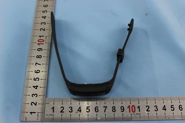
NMTPE961
Nov 11, 2014Activity Tracker
Equipment Class
DTS - Digital Transmission System
NMTRTHN129-01
Sep 12, 20145 Channel Remote RCC-Thermo Sensor
Equipment Class
DSC - Part 15 Security/Remote Control Transmitter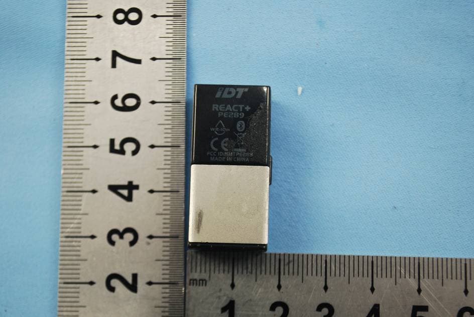
NMTPE289
Aug 21, 20142nd generation activity and sleep monitor wrist device
Equipment Class
DTS - Digital Transmission System