NMTAD182USB Communications Hub
IDT Technology Limited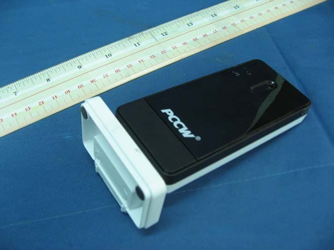
Click to zoom
Application Details
- Equipment Class
- DXX - Part 15 Low Power Communication Device Transmitter
- Date of Grant
- Jun 14, 2011
- Application Purpose
- Original Equipment
- Date of Application
- Jun 14, 2011
- Equipment Note
- USB Communications Hub
- Frequency Range
- 2405.00000000 - 2475.00000000
- Company
- IDT Technology Limited
- Country
- Hong Kong
Documents & Files
Document Text
Text extracted from the exhibit documents filed with the FCC. Open a document above to read the original.
Users Manual
1 1 S E A R C H
Block Diagram
AD182 AD182AD182 AD182 Block Crystal 16MHz Transceiver (NRF24AP2-USB) USB Interface Antenna Matching Network Antenna Revision 1.0Page 9 of 44 nRF24AP2-USB Product Specification 2.2 Block diagram nRF24AP2 is composed of five main blocks as shown in Figure 2. The blocks indicate the interface, power management, the ANT protocol engine, on-chip oscillators and the RF transceiver. Figure 2. Block diagram of nRF24AP2 solution To find more information about each block in the diagram, see Table 1. Table 1. Block diagram cross references NameReference RF transceiverChapter 3 on page 12 ANT protocol engineChapter 4 on page 13 USB interfacesChapter 5 on page 21 On-chip oscillatorsChapter 6 on page 30 Power managementChapter 8 on page 33 nRF24AP2 Computer 16 MHz DEC1 I ref DEC2 VSS VDD ANT1 ANT2 VDD_PA ANT protocol engine Ultra low power 2.4 GHz transceiver USB Power management On-chip oscillators Revision 1.0Page 12 of 44 nRF24AP2-USB Product Specification 3 RF transceiver All transceiver operations are controlled solely by the ANT protocol stack. Configuration of the ANT proto- col stack occurs through a serial interface by issuing ANT commands to nRF24AP2-USB. 3.1 Features Features of the RF transceiver include: •General XWorldwide 2.4 GHz ISM band operation XCommon antenna interface in transmit and receive XGFSK modulation X1 Mbps on air data rate •Transmitter XProgrammable output power: 0, -6, -12 or -18 dBm •Receiver XIntegrated channel filters X-85 dBm sensitivity •RF Synthesizer XFully integrated synthesizer X1 MHz frequency programming resolution X78 RF channels in the 2.4 GHz ISM band XAccepts low cost ± 50 ppm 16 MHz crystal X1 MHz non-overlapping channel spacing 3.2 Block diagram Figure 4. on page 12 shows a block diagram of the RF transceiver in nRF24AP2-USB. Figure 4. Internal circuitry of RF transceiver relative to ANT RF receiver ANT1 ANT2 ANT protocol stack GFSK modulator PA LNA TX filter RX filter RF synthesizer RF transmitter GFSK demodulator
External Photos
INTERTEK TESTING SERVICE Report No.: HK11040585-1 FCC ID: NMTAD182 Equipment Photographs Model: AD182 (External) INTERTEK TESTING SERVICE Report No.: HK11040585-1 FCC ID: NMTAD182 Equipment Photographs Model: AD182 (External) INTERTEK TESTING SERVICE Report No.: HK11040585-1 FCC ID: NMTAD182 Equipment Photographs Model: AD182 (External)
ID Label/Location Info
15 x 5.2mm6 x 1.3mm 15.8 x 1.2mm 21 x 1.2mm 6.9 x 4.9mm 7.4 x 7.4mm IMG_0925.JPG (2272x1704x16M jpeg)
Internal Photos
INTERTEK TESTING SERVICE Report No.: HK11040585-1 FCC ID: NMTAD182 Equipment Photographs Model: AD182 (Internal) INTERTEK TESTING SERVICE Report No.: HK11040585-1 FCC ID: NMTAD182 Equipment Photographs Model: AD182 (Internal) INTERTEK TESTING SERVICE Report No.: HK11040585-1 FCC ID: NMTAD182 Equipment Photographs Model: AD182 (Internal) INTERTEK TESTING SERVICE Report No.: HK11040585-1 FCC ID: NMTAD182 Equipment Photographs Model: AD182 (Internal) INTERTEK TESTING SERVICE Report No.: HK11040585-1 FCC ID: NMTAD182 Equipment Photographs Model: AD182 (Internal)
Operational Description
AD18 AD18AD18 AD182 22 2 Technical Description The USB dongle is a 2.4GHz transceiver device with USB interface and PC software control console. It can act as a bridge between an ANT wireless network and backbone infrastructure. When it finds a “link” signal from another transceiver and then it will send out the authorized information and after proper link setup, both devices will form a channel for transfer of user data all encoded with 2.4GHz RF signal through Antenna and the matching network, from transceiver IC to PC software console for processing and analysis. The matching network is used to match the impedance of the antenna to the nRF24AP2 IC and suppress unwanted spurious transmission. The data signal is transferred through matching network (L1,L2,L3,L4,L5, L6,L7,C3,C5,C6,C13,C14,and C15) and the antenna. All rights reserved. ANT TM is a trademark of Dynastream Innovation Inc. Reproduction in whole or in part is prohibited without the prior written permission of the copyright holder. April 2010 nRF24AP2 nRF24AP2-USB Single-chip ANT TM ultra-low power wireless network solution Product Specification v1.0 Key Features •Second generation single chip ANT solution •Bridge from ANT networks and devices to computers, Macs, and the internet •nRF24AP2- USB supports up to eight ANT (logic) channels – ideal for hubs •World wide 2.4 GHz ISM band operation •USB v2.0 interface •Fully embedded, enhanced ANT protocol stack •Built-in device search and pairing •Built-in timing and power management •Built-in interference handling •Configurable channel period 5.2 ms - 2 s •Broadcast, Acknowledged and Burst communication modes •Burst data rate up to 20 kbps •Simple to complex network topologies: Peer-to-peer, star, tree and practical mesh •Supports public, private and managed networks •Support for ANT+ device profile implementations enabling multivendor interoperability •Fully interoperable with nRF24AP1, Dynastream ANT chipset / module based prod- ucts and other nRF24AP2 variants •RoHS compliant 5x5 mm 32-pin QFN package •Low cost external 16 MHz crystal Applications •Sports •Wellness •Home health monitoring •Home/industrial automation •Environmental sensor networks •Active RFID •Logistics/goods tracking •Audience-response systems Revision 1.0Page 2 of 44 nRF24AP2-USB Product Specification Liability disclaimer Nordic Semiconductor ASA reserves the right to make changes without further notice to the product to improve reliability, function or design. Nordic Semiconductor ASA does not assume any liability arising out of the application or use of any product or circuits described herein. All application information is advisory and does not form part of the specification. Limiting values Stress above one or more of the limiting values may cause permanent damage to the device. These are stress ratings only and operation of the device at these or at any other conditions above those given in the specifications are not implied. Exposure to limiting values for extended periods may affect device reliability. Life support applications Nordic Semiconductor’s products are not designed for use in life support appliances, devices, or systems where malfunction of these products can reasonably be expected to result in personal injury. Nordic Semi- conductor ASA customers using or selling these products for use in such applications do so at their own risk and agree to fully indemnify Nordic Semiconductor ASA for any damages resulting from such improper use or sale. Contact details For your nearest dealer, please see www.nordicsemi.com. Main office: Otto Nielsens veg 12 7004 Trondheim Phone: +47 72 89 89 00 Fax: +47 72 89 89 89 www.nordicsemi.com Datasheet status Objective product specificationThis product specification contains target specifications for Nordic Semiconductor’s product development. Preliminary product specification This product specification contains preliminary data; supplementary data may be published from Nordic Semiconductor ASA later. Product specificationThis product specification contains final product specifications. Nordic Semiconductor ASA reserves the right to make changes at any time without notice in order to improve design and supply the best possible product. Revision 1.0Page 3 of 44 nRF24AP2-USB Product Specification RoHS statement This product meets the requirements of Directive 2002/95/EC of the European Parliament and of the Council on the Restriction of Hazardous Substances (RoHS). Complete hazardous substance reports as well as material composition reports for all active Nordic products can be found on our web site www.nordicsemi.com . Revision History DateVersionDescription April 20101.0Product Specification Revision 1.0Page 4 of 44 nRF24AP2-USB Product Specification Contents 1Introduction ............................................................................................... 6 1.1Prerequisites ........................................................................................ 6 1.2Writing conventions .............................................................................. 6 2Product overview ...................................................................................... 7 2.1Features ............................................................................................... 8 2.2Block diagram ...................................................................................... 9 2.3Pin Assignments .................................................................................. 10 2.4Pin Functions ....................................................................................... 10 2.4.1Power supply pins ........................................................................... 11 2.4.2Reset pin ......................................................................................... 11 3RF transceiver ........................................................................................... 12 3.1Features ...................................…
Text truncated - open the document above for the full version.
Test Report
INTERTEK TESTING SERVICES Report No.: HK11040585-1 Sample No.: 2/2 Code: FCC15C_d / Effective Date: 26 Jan 2010 ( of ) Average Factor Plot - Pursuant to FCC Part 15 Section 15.249 Requirement (Pass/Fail) INTERTEK TESTING SERVICES Report No.: HK11040585-1 Sample No.: 2/2 Code: FCC15C_d / Effective Date: 26 Jan 2010 ( of ) Average Factor Plot - Pursuant to FCC Part 15 Section 15.249 Requirement (Pass/Fail) INTERTEK TESTING SERVICES Report No.: HK11040585-1 Sample No.: 2/2 Code: FCC15C_d / Effective Date: 26 Jan 2010 ( of ) Average Factor Plot - Pursuant to FCC Part 15 Section 15.249 Requirement (Pass/Fail)
Test Report
INTERTEK TESTING SERVICES Report No.: HK11040585-1 Sample No.: 2/2 Code: FCC15C_d / Effective Date: 26 Jan 2010 ( of ) Bandedge Plot - Pursuant to FCC Part 15 Section 15.249 Requirement (Pass/Fail) OATS = 100.4dBuV/m Field Strength (Peak) =100.4 - 36.16 dBuV/m =64.24 dBuV/m (Limit: 74 dBuV/m) Field Strength (Average) =64.24 - AF dBuV/m =64.24 - 29.0 dBuV/m =35.24 dBuV/m (Limit: 54 dBuV/m) OATS = 100.1dBuV/m Field Strength (Peak) =100.1 - 41.23 dBuV/m =58.87 dBuV/m (Limit: 74 dBuV/m) Field Strength (Average) =58.87 - AF dBuV/m =58.87 - 29.0 dBuV/m =29.87 dBuV/m (Limit: 54 dBuV/m)
Test Report
Report no.: HK11040585-1 Mode: Transmitting Ctrl No.: N/A 6DB AC 150 kHz30 MHz dBμV dBμV 1 PK CLRWR 2 AV CLRWR SGL TDS RBW 9 kHz MT 1 s PREAMP OFFAtt 10 dB AUTO 1 MHz10 MHz 0 10 20 30 40 50 60 70 80 90 100 CF15MAV CF15MQP HK11040585 (D0585C1) Date: 26.APR.2011 19:05:35 Report no.: HK11040585-1 Mode: Transmitting Ctrl No.: N/A EDIT PEAK LIST (Final Measurement Results) Trace1: CF15MQP Trace2: CF15MAV Trace3: --- TRACE FREQUENCY LEVEL dBμV DELTA LIMIT dB 2 CISPR Average235.5 kHz 33.66 N -18.58 1 Quasi Peak 240 kHz 45.72 N -16.36 2 CISPR Average496.5 kHz 35.11 N -10.94 1 Quasi Peak 501 kHz 37.44 N -18.55 1 Quasi Peak 604.5 kHz 34.55 N -21.44 2 CISPR Average730.5 kHz 35.79 L1 -10.21 2 CISPR Average847.5 kHz 29.71 N -16.28 2 CISPR Average1.23 MHz 27.40 N -18.59 2 CISPR Average2.076 MHz 28.06 N -17.93 2 CISPR Average13.4205 MHz 38.35 N -11.64 1 Quasi Peak 14.2125 MHz 39.42 N -20.57 2 CISPR Average16.2285 MHz 39.98 N -10.01 1 Quasi Peak 17.0835 MHz 38.95 N -21.05 HK11040585 (D0585C1) Date: 26.APR.2011 19:05:27
Test Report
- The test report only allows to be revised within the retention period unless further standard or the requirement was noticed. - This report is for the exclusive use of Intertek's Client and is provided pursuant to the agreement between Intertek and its Client. Intertek's responsibility and liability are limited to the terms and conditions of the agreement. Intertek assumes no liability to any party, other than to the Client in accordance with the agreement, for any loss, expense or damage occasioned by the use of this report. Only the Client is authorized to permit copying or distribution of this report and then only in its entirety. Any use of the Intertek name or one of its marks for the sale or advertisement of the tested material, product or service must first be approved in writing by Intertek. The observations and test results in this report are relevant only to the sample tested. This report by itself does not imply that the material, product, or service is or has ever been under an Intertek certification program. Intertek Testing Services Hong Kong Ltd. 2/F., Garment Centre, 576 Castle Peak Road, Kowloon, Hong Kong. Tel: (852) 2173 8888 Fax: (852) 2785 5487 Website: www.hk.intertek-etlsemko.com TEST REPORT Report No.: HK11040585-1 IDT Technology Limited Application For Certification (Original Grant) (FCC ID: NMTAD182) Transceiver Prepared and Checked by: Approved by: Signed On File Kung Wing Cheong, Steven Assistant Engineer Chan Chi Hung, Terry Assistant Supervisor Date: June 14, 2011 INTERTEK TESTING SERVICES Report No.: HK11040585-1 FCC ID: NMTAD182 i GENERAL INFORMATION IDT Technology Limited BRAND NAME: Oregon Scientific, MODEL: AD182 FCC ID: NMTAD182 Grantee: IDT Technology Limited Grantee Address: Block C, 9/F., Kaiser Estate, Phase 1, 41 Man Yue Street, Hunghom, Kowloon, Hong Kong. Contact Person: Mr. Thomas Chan Tel: 852-2764 7873 Fax: 852-2765 6620 e-mail: [email protected] Manufacturer: IDT Technology Limited Manufacturer Address: Block 32, Chen Tian Industrial Estate, Xi Xiang, Bao An, Shenzhen, PRC. Brand Name: Oregon Scientific Model: AD182 Type of EUT: Transceiver Description of EUT: USB Communications Hub Serial Number: N/A FCC ID: NMTAD182 Date of Sample Submitted: April 12, 2011 Date of Test: April 28, 2011 Report No.: HK11040585-1 Report Date: June 14, 2011 Environmental Conditions: Temperature: +10 to 40°C Humidity: 10 to 90% INTERTEK TESTING SERVICES Report No.: HK11040585-1 FCC ID: NMTAD182 ii SUMMARY OF TEST RESULT IDT Technology Limited BRAND NAME: Oregon Scientific, MODEL: AD182 FCC ID: NMTAD182 TEST SPECIFICATION REFERENCE RESULTS Maximum Peak Output Power 15.247(b), (c) / RSS-210 A8.4 N/A Hopping Channel Carrier Frequencies Separation 15.247(e) / RSS-210 A8.1 N/A 20dB Bandwidth of the Hopping Channel 15.247(a) / RSS-210 A8.1 N/A Number of Hopping Frequencies 15.247(e) / RSS-210 A8.1 N/A Average Time of Occupancy of Hopping Frequency 15.247(e) / RSS-210 A8.1 N/A Antenna Conducted Spurious Emissions 15.247(d) / RSS-210 A8.5 N/A Radiated Spurious Emissions 15.247(d) / RSS-210 A8.5 N/A RF Exposure Compliance 15.247(i) / RSS-Gen 5.5 N/A Transmitter Power Line Conducted Emissions 15.207 / RSS-Gen 7.2.2 Pass Transmitter Field Strength 15.227 / RSS-310 3.8 N/A Transmitter Field Strength 15.229 / RSS-210 A2.7 N/A Transmitter Field Strength, Bandwidth and Timing Requirement 15.231(a) / RSS-210 A1.1.1 N/A Transmitter Field Strength, Bandwidth and Timing Requirement 15.231(e) / RSS-210 A1.1.5 N/A Transmitter Field Strength and Bandwidth Requirement 15.239 / RSS-210 A2.8 N/A Transmitter Field Strength and Bandwidth Requirement 15.249 / RSS-210 A2.9 Pass Transmitter Field Strength and Bandwidth Requirement 15.235 / RSS-310 3.9 N/A Receiver / Digital Device Radiated Emissions 15.109 / ICES-003 N/A Digital Device Conducted Emissions 15.107 / ICES-003 N/A Note: 1. The EUT uses a permanently attached antenna which, in accordance to section 15.203, is considered sufficient to comply with the pervisions of this section. 2. Pursuant to FCC part 15 Section 15.215(c), the 20 dB bandwidth of the emission was contained within the frequency band designated (mentioned as above) which the EUT operated. The effects, if any, from frequency sweeping, frequency hopping, other modulation techniques and frequency stability over excepted variations in temperature and supply voltage were considered. INTERTEK TESTING SERVICES Report No.: HK11040585-1 FCC ID: NMTAD182 iii Table of Contents 1.0 General Description....................................................................................... 1 1.1 Product Description ...................................................................................... 1 1.2 Related Submittal(s) Grants .......................................................................... 1 1.3 Test Methodology ......................................................................................... 1 1.4 Test Facility .................................................................................................. 1 2.0 System Test Configuration ............................................................................ 2 2.1 Justification................................................................................................... 2 2.2 EUT Exercising Software .............................................................................. 2 2.3 Special Accessories...................................................................................... 2 2.4 Equipment Modification................................................................................. 2 2.5 Measurement Uncertainty ............................................................................. 3 2.6 Support Equipment List and Description........................................................ 3 3.0 Emission Results ........................................................................................... 4 3.1 Field Strength Calculation ............................................…
Text truncated - open the document above for the full version.
Test Setup Photos
INTERTEK TESTING SERVICE Report No: HK11040585-1 FCC ID: NMTAD182 i Configuration Photographs Worst-Case Line-Conducted Emissions (Front View) Model : AD182 INTERTEK TESTING SERVICE Report No: HK11040585-1 FCC ID: NMTAD182 ii Configuration Photographs Worst-Case Line-Conducted Emissions (Back View) Model : AD182 INTERTEK TESTING SERVICE Report No: HK11040585-1 FCC ID: NMTAD182 iii Configuration Photographs Worst-Case Line-Conducted Emissions (Side View) Model : AD182
Test Setup Photos
INTERTEK TESTING SERVICE Report No: HK11040585-1 FCC ID: NMTAD182 Configuration Photographs Worst-Case Conduct Emissions (Front View) Model: AD182 INTERTEK TESTING SERVICE Report No: HK11040585-1 FCC ID: NMTAD182 Configuration Photographs Worst-Case Conduct Emissions (Back View) Model: AD182
Contact Information
Applicant
Alex Chan(Project Manager)
Technical Contact
Intertek Testing Services Hong Kong LtdTerry Chan
[email protected]2173 8503
2/F Garment Centre · Kowloon · Hong Kong
Non-Technical Contact
Intertek Testing Service Hong Kong LtdTerry Chan
[email protected]2173 8503
Test Firm
Intertek Testing Services Hong Kong Ltd.Billy Chow
Technical Specifications
| # | Rule Parts | Frequency Range | Power Output |
|---|---|---|---|
| 1 | 15C | 2.40 GHz - 2.48 GHz | - |
Other Applications from IDT Technology Limited

NMTBAR228-01
Dec 03, 2015Weather+BLE Connected Weather Station
Equipment Class
DTS - Digital Transmission System
NMTRTGN130A-01
Sep 10, 2015Outdoor sensor
Equipment Class
DSC - Part 15 Security/Remote Control Transmitter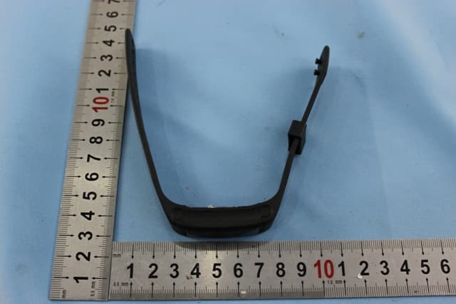
NMTPE961
Nov 11, 2014Activity Tracker
Equipment Class
DTS - Digital Transmission System
NMTRTHN129-01
Sep 12, 20145 Channel Remote RCC-Thermo Sensor
Equipment Class
DSC - Part 15 Security/Remote Control Transmitter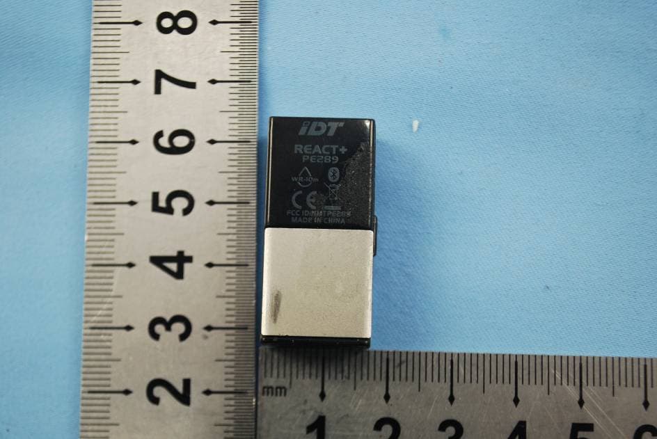
NMTPE289
Aug 21, 20142nd generation activity and sleep monitor wrist device
Equipment Class
DTS - Digital Transmission System