NMTPE912ANYWEAR Slim Pedometer
IDT Technology Limited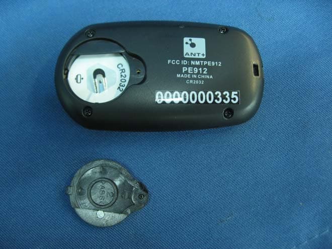
Click to zoom
Application Details
- Equipment Class
- DXX - Part 15 Low Power Communication Device Transmitter
- Date of Grant
- Jun 14, 2011
- Application Purpose
- Original Equipment
- Date of Application
- Jun 14, 2011
- Equipment Note
- ANYWEAR Slim Pedometer
- Frequency Range
- 2405.00000000 - 2475.00000000
- Company
- IDT Technology Limited
- Country
- Hong Kong
Documents & Files
Document Text
Text extracted from the exhibit documents filed with the FCC. Open a document above to read the original.
Users Manual
1 2 3 110 11 12 13 2 3 4 7 8 9 6 5 14 15 16 17 19 18
Block Diagram
PE912 PE912PE912 PE912 Block Crystal 32768Hz Microcontroller (S1C8F360) 3D SENSOR 2.4GHz Transmission IC (nRF24AP1) Crystal 16MHz Antenna Matching Network Antenna PRODUCT SPECIFICATION nRF24AP1 Single Chip 2.4 GHz Radio Transceiver with Embedded ANT Protocol Nordic Semiconductor ASA - Vestre Rosten 81, N-7075 Tiller, Norway - Phone +4772898900 - Fax +4772898989 Revision: 1.0 Page 4 of 25September 2006 1.BLOCK DIAGRAM DVDD VDD=3VVDD=3V XC1 XC2 100:+j175: IREF VDD_PA=1.8V VSS_PA=0V ANT1 ANT2 22k: VSS=0V VSS=0V VDD=3V VSS=0VVSS=0V ANT Protocol Engine PORTSEL 1 Mbps RF Transceiver UART or Synchronous Serial Interface BR2 / SCLK BR1 / SFLOW EXT32K RTS / SEN RXD / SIN TXD / SOUT SUSPEND / SRDY SLEEP / SMSGRDY Timing Figure 1: nRF24AP1 with external components. The “ANT Protocol Engine” shown in Figure 1 is described in the “ANT Message Protocol and Usage” document.
External Photos
INTERTEK TESTING SERVICE Report No.: HK11040580-1 FCC ID: NMTPE912 Equipment Photographs Model: PE912 (External) INTERTEK TESTING SERVICE Report No.: HK11040580-1 FCC ID: NMTPE912 Equipment Photographs Model: PE912 (External)
Internal Photos
INTERTEK TESTING SERVICE Report No.: HK11040580-1 FCC ID: NMTPE912 Equipment Photographs Model: PE912 (Internal) INTERTEK TESTING SERVICE Report No.: HK11040580-1 FCC ID: NMTPE912 Equipment Photographs Model: PE912 (Internal) INTERTEK TESTING SERVICE Report No.: HK11040580-1 FCC ID: NMTPE912 Equipment Photographs Model: PE912 (Internal) INTERTEK TESTING SERVICE Report No.: HK11040580-1 FCC ID: NMTPE912 Equipment Photographs Model: PE912 (Internal)
Operational Description
PE912 PE912PE912 PE912 Technical Description The pedometer is a 2.4GHz 3D device. It is integrated with a microcontroller, a 3D sensor, and a transceiver IC. It stores the current and previous 9 days’ information (including step count, distance traveled, calorie). It also has PC connection via ANT + RF chip. The microcontroller reads the signal from 3D sensor and activates the nRF24AP1 to send encoded 2.4GHz RF signal containing the user exercise data, timing information, and device ID to the USB dongle, which is connected to PC via a USB cable. PC software will calculate and display the information for analysis and may store the information too. The RF output of the nRF24AP1 transceiver IC is connected to the antenna via an Antenna matching network. This network is used to match the impedance of the antenna to the nRF24AP1 IC and suppress unwanted spurious transmission. The data signal is transferred through matching network (LL1, LL2, LL3, LL4, LL5, LL6, LL7, LL8, CC4, CC5, CC6, CC7, CC8, CC10 and CC13) fed to the antenna. PRODUCT SPECIFICATION Nordic Semiconductor ASA - Vestre Rosten 81, N-7075 Tiller, Norway - Phone +4772898900 - Fax +4772898989 Revision: 1.0 Page 1 of 25 September 2006 Single chip 2.4 GHz Transceiver with Embedded ANT protocol FEATURES • Integrated PAN (Personal Area Network) • Drop in wireless networking with simple serial interface • 2.4GHz Worldwide ISM Band • Ultra-low power (coin cell battery) • Fully scaleable • Broadcast, Acknowledged or Burst Data • Message rates 0.5Hz -> 200Hz (8byte data payload) • Burst transfer rates up to 20kbps (true data throughput) • Public and private networks • 1 Mbps RF data rate • 125 RF channels APPLICATIONS • Sensor Networks • Industrial Automation • Home Automation • Sports Monitoring GENERAL DESCRIPTION The nRF24AP1 is an ultra-low power single-chip radio transceiver with embedded ANT protocol for personal area networks. The transceiver’s RF operating frequency range falls within the world-wide 2.4 - 2.5 GHz RF ISM band, allowing for regulatory compliance and product sales into global markets. QUICK REFERENCE DATA Parameter Value Unit Minimum supply voltage 1.9 V Maximum output power 0 dBm Maximum data rate (over the air) 1000 kbps Temperature range -40 to +85 °C Sensitivity -80 dBm Average current consumption as low as 30 μA Peak current consumption TX @-5dBm 13.5mA for 350us mA Peak current consumption RX 22mA for 600us mA Max # of simultaneous connections 1 >65000 connections Max # of simultaneous independent 2-way connections 4 2-way connections Maximum sustained transfer rate (all data – no overhead) 2 20 kbps CR2032 Battery life in a typical sensor application 3 5 years Table 1: nRF24AP1 quick reference data 1 Using Shared Channel Network 2 Transfer rate refers to data rate of the end application’s message payload 3 Message interval of 2s, 1 hour/day usage Simple Networks Complex Networks Independent Networks Broadcast Networks Shared Channel Networks nRF24AP1 ANT by Dynastream © 2005 all ri ghts reserved PRODUCT SPECIFICATION nRF24AP1 Single Chip 2.4 GHz Radio Transceiver with Embedded ANT Protocol Nordic Semiconductor ASA - Vestre Rosten 81, N-7075 Tiller, Norway - Phone +4772898900 - Fax +4772898989 Revision: 1.0 Page 2 of 25 September 2006 The transceiver consists of the ANT fully integrated protocol engine, frequency synthesizer, power amplifier, crystal oscillator and modulator, and can be interfaced to a host micro controller over either a synchronous or asynchronous serial interface. Designed to run on a wrist-watch coin cell battery, current consumption of the device is extremely low - a typical sensor application can operate on approximately 30μA average current consumption. Short, low peak current transitions are battery friendly. The embedded ANT protocol makes for easy, low cost integration. Eliminating the need for 3 rd party RF protocol implementation, the on-chip ANT protocol combined with the 2.4GHz transceiver enables system and application developers to interact with the nRF24AP1 as a black box wireless solution. The simple serial interface (asynchronous or synchronous) to the device allows for flexibility and scalability from ultra-low power sensors (30μA) through to higher data rate (20kbps) applications implemented in a multitude of network configurations. Networks can be scaled from as little as two nodes to thousands. With 2 32 unique IDs, multiple radio frequencies, public and private network management and scalable data rates, an unlimited number of network configurations and applications are possible. Prior to reading this document, the “ANT Message Protocol and Usage” document should be read to gain understanding of the ANT protocol capabilities. REFERENCES Ref. No. Doc. No. Revision Title 1 D00000794 1.0 Interfacing with ANT General Purpose Chipset and Modules (Part of nRF24AP1 Specification) 2 D00000652 1.36 ANT Message Protocol and Usage Table 2 nRF24AP1 referenced documents For more information see: www.nordicsemi.no PRODUCT SPECIFICATION nRF24AP1 Single Chip 2.4 GHz Radio Transceiver with Embedded ANT Protocol Nordic Semiconductor ASA - Vestre Rosten 81, N-7075 Tiller, Norway - Phone +4772898900 - Fax +4772898989 Revision: 1.0 Page 3 of 25 September 2006 TABLE OF CONTENTS FEATURES .....................................................................................................................................................1 APPLICATIONS.............................................................................................................................................1 GENERAL DESCRIPTION............................................................................................................................1 QUICK REFERENCE DATA.........................................................................................................................1 REFERENCES ...................................................................................................................…
Text truncated - open the document above for the full version.
Test Report
INTERTEK TESTING SERVICES Report No.: HK11040580-1 Sample No.: 2/2 Code: FCC15C_d / Effective Date: 26 Jan 2010 ( of ) Average Factor Plot - Pursuant to FCC Part 15 Section 15.249 Requirement (Pass/Fail) INTERTEK TESTING SERVICES Report No.: HK11040580-1 Sample No.: 2/2 Code: FCC15C_d / Effective Date: 26 Jan 2010 ( of ) Average Factor Plot - Pursuant to FCC Part 15 Section 15.249 Requirement (Pass/Fail)
Test Report
INTERTEK TESTING SERVICES Report No.: HK11040580-1 Sample No.: 2/2 Code: FCC15C_d / Effective Date: 26 Jan 2010 ( of ) Bandedge Plot - Pursuant to FCC Part 15 Section 15.249 Requirement (Pass/Fail) OATS = 90.4dBuV/m Field Strength (Peak) =90.4 - 20.93 dBuV/m =69.47 dBuV/m (Limit: 74 dBuV/m) Field Strength (Average) =69.47 - AF dBuV/m =69.47 - 54.0 dBuV/m =15.47 dBuV/m (Limit: 54 dBuV/m) OATS = 89.6dBuV/m Field Strength (Peak) =89.6 – 26.9 dBuV/m =62.7 dBuV/m (Limit: 74 dBuV/m) Field Strength (Average) =62.7 - AF dBuV/m =62.7 - 54.0 dBuV/m =8.7 dBuV/m (Limit: 54 dBuV/m)
Test Report
- The test report only allows to be revised within the retention period unless further standard or the requirement was noticed. - This report is for the exclusive use of Intertek's Client and is provided pursuant to the agreement between Intertek and its Client. Intertek's responsibility and liability are limited to the terms and conditions of the agreement. Intertek assumes no liability to any party, other than to the Client in accordance with the agreement, for any loss, expense or damage occasioned by the use of this report. Only the Client is authorized to permit copying or distribution of this report and then only in its entirety. Any use of the Intertek name or one of its marks for the sale or advertisement of the tested material, product or service must first be approved in writing by Intertek. The observations and test results in this report are relevant only to the sample tested. This report by itself does not imply that the material, product, or service is or has ever been under an Intertek certification program. Intertek Testing Services Hong Kong Ltd. 2/F., Garment Centre, 576 Castle Peak Road, Kowloon, Hong Kong. Tel: (852) 2173 8888 Fax: (852) 2785 5487 Website: www.hk.intertek-etlsemko.com TEST REPORT Report No.: HK11040580-1 IDT Technology Limited Application For Certification (Original Grant) (FCC ID: NMTPE912) Transceiver Prepared and Checked by: Approved by: Signed On File Kung Wing Cheong, Steven Assistant Engineer Chan Chi Hung, Terry Assistant Supervisor Date: June 14, 2011 INTERTEK TESTING SERVICES Report No.: HK11040580-1 FCC ID: NMTPE912 i GENERAL INFORMATION IDT Technology Limited BRAND NAME: Oregon Scientific, MODEL: PE912 FCC ID: NMTPE912 Grantee: IDT Technology Limited Grantee Address: Block C, 9/F., Kaiser Estate, Phase 1, 41 Man Yue Street, Hunghom, Kowloon, Hong Kong. Contact Person: Thomas Chan Tel: 852-27647873 Fax: 852-27656620 e-mail: [email protected] Manufacturer: IDT Technology Limited Manufacturer Address: Block 32, Chen Tian Industrial Estate, Xi Xiang, Bao An, Shenzhen, PRC. Brand Name: Oregon Scientific Model: PE912 Type of EUT: Transceiver Description of EUT: ANYWEAR Slim Pedometer Serial Number: N/A FCC ID: NMTPE912 Date of Sample Submitted: April 12, 2011 Date of Test: April 28, 2011 Report No.: HK11040580-1 Report Date: June 14, 2011 Environmental Conditions: Temperature: +10 to 40°C Humidity: 10 to 90% INTERTEK TESTING SERVICES Report No.: HK11040580-1 FCC ID: NMTPE912 ii SUMMARY OF TEST RESULT IDT Technology Limited BRAND NAME: Oregon Scientific, MODEL: PE912 FCC ID: NMTPE912 TEST SPECIFICATION REFERENCE RESULTS Maximum Peak Output Power 15.247(b), (c) / RSS-210 A8.4 N/A Hopping Channel Carrier Frequencies Separation 15.247(e) / RSS-210 A8.1 N/A 20dB Bandwidth of the Hopping Channel 15.247(a) / RSS-210 A8.1 N/A Number of Hopping Frequencies 15.247(e) / RSS-210 A8.1 N/A Average Time of Occupancy of Hopping Frequency 15.247(e) / RSS-210 A8.1 N/A Antenna Conducted Spurious Emissions 15.247(d) / RSS-210 A8.5 N/A Radiated Spurious Emissions 15.247(d) / RSS-210 A8.5 N/A RF Exposure Compliance 15.247(i) / RSS-Gen 5.5 N/A Transmitter Power Line Conducted Emissions 15.207 / RSS-Gen 7.2.2 N/A Transmitter Field Strength 15.227 / RSS-310 3.8 N/A Transmitter Field Strength 15.229 / RSS-210 A2.7 N/A Transmitter Field Strength, Bandwidth and Timing Requirement 15.231(a) / RSS-210 A1.1.1 N/A Transmitter Field Strength, Bandwidth and Timing Requirement 15.231(e) / RSS-210 A1.1.5 N/A Transmitter Field Strength and Bandwidth Requirement 15.239 / RSS-210 A2.8 N/A Transmitter Field Strength and Bandwidth Requirement 15.249 / RSS-210 A2.9 Pass Transmitter Field Strength and Bandwidth Requirement 15.235 / RSS-310 3.9 N/A Receiver / Digital Device Radiated Emissions 15.109 / ICES-003 N/A Digital Device Conducted Emissions 15.107 / ICES-003 N/A Note: 1. The EUT uses a permanently attached antenna which, in accordance to section 15.203, is considered sufficient to comply with the pervisions of this section. 2. Pursuant to FCC part 15 Section 15.215(c), the 20 dB bandwidth of the emission was contained within the frequency band designated (mentioned as above) which the EUT operated. The effects, if any, from frequency sweeping, frequency hopping, other modulation techniques and frequency stability over excepted variations in temperature and supply voltage were considered. INTERTEK TESTING SERVICES Report No.: HK11040580-1 FCC ID: NMTPE912 iii Table of Contents 1.0 General Description....................................................................................... 1 1.1 Product Description ...................................................................................... 1 1.2 Related Submittal(s) Grants .......................................................................... 1 1.3 Test Methodology ......................................................................................... 1 1.4 Test Facility .................................................................................................. 1 2.0 System Test Configuration ............................................................................ 2 2.1 Justification................................................................................................... 2 2.2 EUT Exercising Software .............................................................................. 2 2.3 Special Accessories...................................................................................... 2 2.4 Equipment Modification................................................................................. 2 2.5 Measurement Uncertainty ............................................................................. 2 2.6 Support Equipment List and Description........................................................ 2 3.0 Emission Results ........................................................................................... 3 3.1 Field Strength Calculation ...................................................…
Text truncated - open the document above for the full version.
Test Setup Photos
INTERTEK TESTING SERVICE Report No: HK11040580-1 FCC ID: NMTPE912 Configuration Photographs Worst-Case Radiated Emissions (Front View) Model: PE912 INTERTEK TESTING SERVICE Report No: HK11040580-1 FCC ID: NMTPE912 Configuration Photographs Worst-Case Radiated Emissions (Back View) Model: AD203
Contact Information
Applicant
Alex Chan(Project Manager)
Technical Contact
Intertek Testing Services Hong Kong LtdTerry Chan
[email protected]2173 8503
2/F Garment Centre · Kowloon · Hong Kong
Non-Technical Contact
Intertek Testing Services Hong Kong LtdTerry Chan
[email protected]2173 8503
Test Firm
Intertek Testing Services Hong Kong Ltd.Billy Chow
Technical Specifications
| # | Rule Parts | Frequency Range | Power Output |
|---|---|---|---|
| 1 | 15C | 2.40 GHz - 2.48 GHz | - |
Other Applications from IDT Technology Limited

NMTBAR228-01
Dec 03, 2015Weather+BLE Connected Weather Station
Equipment Class
DTS - Digital Transmission System
NMTRTGN130A-01
Sep 10, 2015Outdoor sensor
Equipment Class
DSC - Part 15 Security/Remote Control Transmitter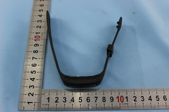
NMTPE961
Nov 11, 2014Activity Tracker
Equipment Class
DTS - Digital Transmission System
NMTRTHN129-01
Sep 12, 20145 Channel Remote RCC-Thermo Sensor
Equipment Class
DSC - Part 15 Security/Remote Control Transmitter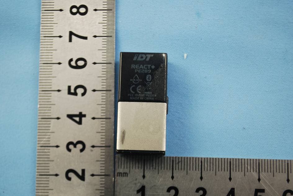
NMTPE289
Aug 21, 20142nd generation activity and sleep monitor wrist device
Equipment Class
DTS - Digital Transmission System