NMTRTGR368NA-01Remote Thermo-Hygrometer Sensor
IDT Technology Limited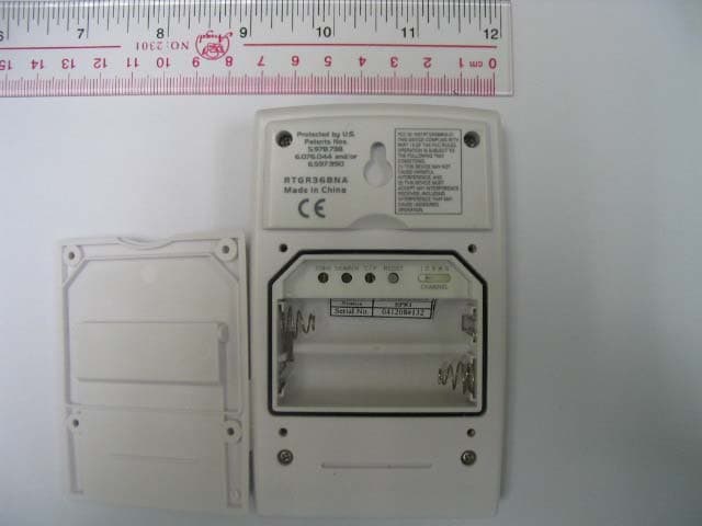
Click to zoom
Application Details
- Equipment Class
- DXX - Part 15 Low Power Communication Device Transmitter
- Date of Grant
- Apr 12, 2005
- Application Purpose
- Original Equipment
- Date of Application
- Apr 12, 2005
- Equipment Note
- Remote Thermo-Hygrometer Sensor
- Frequency Range
- 433.92000000 - 433.92000000
- Company
- IDT Technology Limited
- Country
- Hong Kong
Documents & Files
Document Text
Text extracted from the exhibit documents filed with the FCC. Open a document above to read the original.
Users Manual
Remote Thermo-Hygro Sensor Model: RTGR368NA USER MANUAL GETTING STARTED BATTERIES Remote unit uses 2 x UM-3 (AA) 1.5V. Insert batteries before fi rst use, matching the polarity as shown in the battery compartment. For best results, install batteries in the remote sensor before the main unit. Press RESET after each battery change. NOTE Do not use rechargeable batteries. NOTE It is recommended that you use alkaline batteries with this product for longer performance. INTRODUCTION Thank you for selecting the Oregon Scientifi c TM Remote Thermo- Hygro Sensor (RTGR368NA). This product is compatible with the BAR933HGA clock. Keep this manual handy as you use your new product. It contains practical step-by-step instructions, as well as technical specifi cations and warnings you should know. PRODUCT OVERVIEW 1. LCD display 2. LED status indicator 3. Ventilation duct 4. Fold-out stand 1. Signal reception 2. US time zones 3. Channel number 4. Temp / humidity readings 5. Low battery icon 6. Time 7. Temp (°C or °F) 8. Humidity % 1. Wall mount 2. ZONE button 3. SEARCH button 4. °C / °F button 5. RESET button 6. CHANNEL switch (1-5) 7. Battery compartment DECLARATION OF CONFORMITY The following information is not to be used as contact for support or sales. Please call our customer service number (listed on our website at www.oregonscientifi c.com ), or on the warranty card for this product) for all in quir ies instead. We Name: Oregon Scientifi c, Inc. Address: 19861 SW 95th Place, Tualatin, Oregon 97062 USA Telephone No.: 1-800-853-8883 Fax No.: 1-503-684-3332 declare that the product Product No.: RTGR368NA Product Name: Remote Thermo-Hygro Sensor Manufacturer: IDT Technology Limited Address: Block C, 9/F, Kaiser Estate, Phase 1, 41 Man Yue St., Hung Hom, Kowloon, Hong Kong is in conformity with Part 15 of the FCC Rules. Operation is subject to the following two con di tions: 1) This device may not cause harmful interference. 2) This device must accept any interference received, including interference that may cause undesired operation. © 2005 Oregon Scientifi c. All rights reserved P/N.: 086-003866-015 REMOTE SENSOR The RTGR368NA sensor collects temperature and humidity readings, and signals from offi cial time-keeping organizations for the atomic clock. SET UP THERMO / HYGRO SENSOR RTGR368NA) 1. Open the battery compartment with a small Phillips screw- driv er. 2. Insert the batteries. 3. Set the channel and radio signal format. The switches are lo cat ed in the battery compartment. 4. Press RESET. Then set the temperature unit. 5. Press ZONE to select the US time zone: P (Pacifi c), M (Mountain), C (Central) or E (Eastern). 6. Close the battery compartment. For best results: • Insert the batteries and select the unit, channel, and time zone before you mount the sensor. • Place the sensor out of direct sunlight and moisture. • Do not place the sensor more than 230 feet (70 meters) from the main (indoor) unit. • Position the sensor so that it faces the main (indoor) unit, min i miz ing obstructions such as doors, walls, and fur ni ture. • Place the sensor in a location with a clear view to the sky, away from metallic or electronic objects. • Position the sensor close to the main unit during cold winter months as below-freezing temperatures may affect battery performance and signal transmission. NOTE The transmission range may vary and is subject to the receiving range of the main unit. You may need to experiment with various locations to get the best results. Standard Alkaline batteries contain sig nifi cant amounts of water. Be cause of this they will freeze in low temperatures of approximately 10ºF. Disposable Lithium bat ter ies have a much lower threshold for tem per a ture with an estimated freezing range of below -40ºF. The Liquid Crystal Display in out door ther mom e ters will remain operational to -20ºF with ad e quate power. Wireless ranges can be impacted by a variety of factors such as extremely cold temperatures. Extreme cold may temporarily reduce the effective range between the sensor and the base station. If the unit's performance fails due to low temperature, the unit will resume proper functioning as the temperature rises to within the normal temperature range (i.e. no permanent damage will occur to the unit due to low temperatures). RESET SYSTEM Press RESET when you change the batteries and whenever performance is not behaving as expected (for example, you are unable to establish radio frequency link with remote unit). NOTE When you press RESET, all settings will return to default value, and you will lose all stored information. SAFETY AND CARE Clean the product with a slightly damp cloth and alcohol-free, mild detergent. Avoid dropping the product or placing it in a high-traffi c location. WARNINGS This product is designed to give you years of service if handled properly. Oregon Scientifi c will not be responsible for any deviations in the usage of the device from those specifi ed in the user instructions or any unapproved alterations or repairs of the product. Observe the following guidelines: • Never immerse the product in water. This can cause electrical shock and damage the product. • Do not subject the main unit to extreme force, shock, or fl uctuations in temperature or humidity. To fold out the stand: To use the wall mount: SWITCHOPTION ChannelIf you are using more than one sensor, select a different channel for each sensor. Radio Signal FormatEU (DCF) / UK (MSF) SWITCH OPTION Temp°C / °F 1 2 3 4 1 3 4 5 2 6 7 PROBLEM SYMPTOM REMEDY Remote sensor Cannot locate remote sensor Data does not match main unit Check batteries Check location Initiate a manual sensor search 1 2 3 4 5 6 7 • Do not tamper with the internal components. • Do not mix new and old batteries or batteries of different types. • Do not use rechargeable batteries with this product. • Remove the batteries if storing this product for a long period of time. • Do not scratch the LCD display. NOTE The technical spec…
Text truncated - open the document above for the full version.
External Photos
www.tuv.com Appendix 3 Prüfbericht - Nr.: Test Report No. 14008233 001 Seite 1 von 2 Page 1 of 2 www.tuv.com Appendix 3 Prüfbericht - Nr.: Test Report No. 14008233 001 Seite 2 von 2 Page 2 of 2
ID Label/Location Info
www.tuv.com Appendix 5 Prüfbericht - Nr.: Test Report No. 14008233 001 Seite 8 von 9 Page 8 of 9
Internal Photos
www.tuv.com Appendix 4 Prüfbericht - Nr.: Test Report No. 14008233 001 Seite 1 von 5 Page 1 of 5 www.tuv.com Appendix 4 Prüfbericht - Nr.: Test Report No. 14008233 001 Seite 2 von 5 Page 2 of 5 www.tuv.com Appendix 4 Prüfbericht - Nr.: Test Report No. 14008233 001 Seite 3 von 5 Page 3 of 5 www.tuv.com Appendix 4 Prüfbericht - Nr.: Test Report No. 14008233 001 Seite 4 von 5 Page 4 of 5 www.tuv.com Appendix 4 Prüfbericht - Nr.: Test Report No. 14008233 001 Seite 5 von 5 Page 5 of 5
Test Report
www.tuv.com Test Report No.: 14008233 001 Date: 02.03.2005 Page 2 of 13 Test Summary Radiated Emission of Carrier Frequency Result: Pass Spurious Radiated Emissions Result: Pass Bandwidth Measurement Result: Pass www.tuv.com Test Report No.: 14008233 001 Date: 02.03.2005 Page 3 of 13 Contents General Remarks ...................................................................................................4 Complementary Materials.................................................................................................. 4 List of Test and Measurement Instruments.........................................................5 General Product Information ................................................................................6 Product Function and Intended Use................................................................................. 6 Circuit Description .............................................................................................................6 Ratings and System Details .............................................................................................. 6 Independent Operation Modes.......................................................................................... 7 Submitted Documents ....................................................................................................... 7 Related Submittal(s) Grants .............................................................................................. 7 Test Set-up and Operation Mode..........................................................................8 Principle of Configuration Selection ................................................................................ 8 Test Operation and Test Software .................................................................................... 8 Special Accessories and Auxiliary Equipment ............................................................... 8 Countermeasures to achieve EMC Compliance.............................................................. 8 Test Methodology ..................................................................................................9 Radiated Emission ............................................................................................................. 9 Field Strength Calculation ................................................................................................. 9 Test Results .........................................................................................................10 Radiated Emission of Carrier Frequency Section 15.231(b) ..................................... 10 Spurious Radiated Emissions Section 15.231(b)....................................................... 11 Bandwidth Measurement Section 15.231(c) ............................................................... 13 www.tuv.com Test Report No.: 14008233 001 Date: 02.03.2005 Page 4 of 13 General Remarks Complementary Materials All attachments are integral parts of this test report. This applies especially to the following appendix: Appendix 1: Test Results Appendix 2: Test Setup Appendix 3: EUT External Photo Appendix 4: EUT Internal Photo Appendix 5: FCCID Label, Block Diagram, Schematics and User manual. www.tuv.com Test Report No.: 14008233 001 Date: 02.03.2005 Page 5 of 13 List of Test and Measurement Instruments Kind of Equipment Manufacturer Type S/N Test Receiver Rohde & Schwarz ESVS30 842807/009 Biconical Antenna Rohde & Schwarz HK116 841489/015 Log.-Periodic Antenna Rohde & Schwarz HL223 841516/017 Double Ridge Horn Antenna EMCO 3115 9002-3351 Double Ridge Horn Antenna EMCO 3115 9002-3347 Signal Generator Rohde & Schwarz SMY 01 844146/024 Signal Generator Rohde & Schwarz SMY 01 844146/023 Spectrum Analyzer Rohde & Schwarz FSP30 1093.4495K30 www.tuv.com Test Report No.: 14008233 001 Date: 02.03.2005 Page 6 of 13 General Product Information Product Function and Intended Use The equipment under test ( EUT) is a transmitter for a weather station operating at 433.92 MHz. The EUT sense the temperature and humidity level, then transmit this information to the associated weather station. A transmitter transmits signal for every 39 seconds, and the signal on period is about 0.39ms. It activated automatically shall cease transmission within 2 seconds after activation. Hence it operates 92 times per hour. FCC ID NMTRTGR368NA-01 Model Product description RTGR368NA Remote Thermo-Hygrometer Sensor Circuit Description This unit is composed of Temperature (H5) and Humidity (H6) detecting section, RCC receiving section ( U1) and transmitter section. Transmitter is made of Q5 as a Colipittis oscillator, where X1, the 433.92MHz SAW resonator provides the centre frequency/. L2, L4, C16, C17 and C18 perform as the matching network. R29, R30 and R31 perform as the attenuator. Ratings and System Details Transmitter Operated Frequency : 433.92 MHz Frequency deviation of Crystal : ± 75KHz Number of channels : 5 Type of antenna : Integral antenna Power supply : Battery operated 3.0V Ports : none Protection Class : III Equipment Class : B www.tuv.com Test Report No.: 14008233 001 Date: 02.03.2005 Page 7 of 13 Independent Operation Modes The basic operation modes are: - Reset Button : Press to reset all value to default values. - Channel selection. - ° C/F display format selection. - Search button: Press to enable the auto-search for RF signal. For further information refer to User Manual Submitted Documents The submitted documents are listed as follow: - Circuit diagram - Block diagram - User manual - FCC ID label Related Submittal(s) Grants This is a single application for certification of the transmitter. www.tuv.com Test Report No.: 14008233 001 Date: 02.03.2005 Page 8 of 13 Test Set-up and Operation Mode Principle of Configuration Selection Emission: The equipment under test (EUT) was configured to measure its highest possible radiation level. The test modes were adapted accordingly in reference to the instructions f…
Text truncated - open the document above for the full version.
Test Report
www.tuv.com Appendix 1 Prüfbericht - Nr.: Test Report No. 14008233 001 Seite 1 von 5 Page 1 of 5 www.tuv.com Appendix 1 Prüfbericht - Nr.: Test Report No. 14008233 001 Seite 2 von 5 Page 2 of 5 Ref 110 dBμVAtt 40 dB A RBW 1 MHz VBW 1 MHz * SGL MAXH Center 433.9626 MHz300 ms/ SWT 3 s 1 PK 10 20 30 40 50 60 70 80 90 100 110 Marker 1 [T1] 93.52 dBμV 253.000000 ms Delta 2 [T1] 0.09 dB 378.000000 ms Delta 3 [T1] -0.07 dB 2.004000 s Delta 4 [T1] 0.08 dB 2.381000 s 1 2 3 4 Date: 6.JAN.2005 14:19:47 - The EUT was modified into continuous transmission mode, the graph shows two “on” signals. - From marker 1 to marker 2, the total “on” time is 378ms. - Time from marker 3 to marker 4 is the next “on” time signal is 377ms. www.tuv.com Appendix 1 Prüfbericht - Nr.: Test Report No. 14008233 001 Seite 3 von 5 Page 3 of 5 www.tuv.com Appendix 1 Prüfbericht - Nr.: Test Report No. 14008233 001 Seite 4 von 5 Page 4 of 5 www.tuv.com Appendix 1 Prüfbericht - Nr.: Test Report No. 14008233 001 Seite 5 von 5 Page 5 of 5
Test Setup Photos
www.tuv.com Appendix 2 Prüfbericht - Nr.: Test Report No. 14008233 001 Seite 1 von 1 Page 1 of 1 Set-up for Radiation Emission ( Transmitter)
Contact Information
Applicant
Alex Chan(Project Manager)
Technical Contact
T�V Rheinland Hong Kong Ltd.Prudence Poon
[email protected]+852-2192-1000
Unit 8, 25/F., Skyline Tower · Hong Kong · Hong Kong
Test Firm
Hong Kong Productivity CouncilIr Angel Wong Yuen-yee
Technical Specifications
| # | Rule Parts | Frequency Range | Power Output |
|---|---|---|---|
| 1 | 15C | 433.92 MHz - 433.92 MHz | - |
Other Applications from IDT Technology Limited

NMTBAR228-01
Dec 03, 2015Weather+BLE Connected Weather Station
Equipment Class
DTS - Digital Transmission System
NMTRTGN130A-01
Sep 10, 2015Outdoor sensor
Equipment Class
DSC - Part 15 Security/Remote Control Transmitter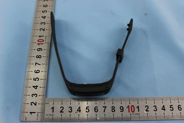
NMTPE961
Nov 11, 2014Activity Tracker
Equipment Class
DTS - Digital Transmission System
NMTRTHN129-01
Sep 12, 20145 Channel Remote RCC-Thermo Sensor
Equipment Class
DSC - Part 15 Security/Remote Control Transmitter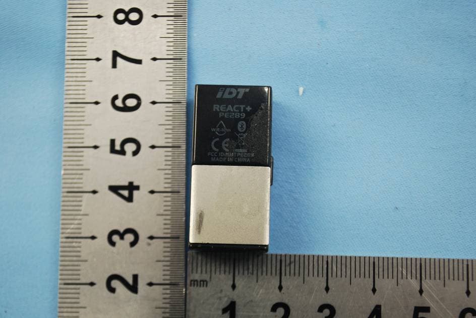
NMTPE289
Aug 21, 20142nd generation activity and sleep monitor wrist device
Equipment Class
DTS - Digital Transmission System