NMTTHR122NX-01Remote Thermometer
IDT Technology Limited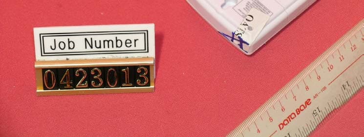
Click to zoom
Application Details
- Equipment Class
- DSC - Part 15 Security/Remote Control Transmitter
- Date of Grant
- Apr 14, 2005
- Application Purpose
- Original Equipment
- Date of Application
- Apr 14, 2005
- Equipment Note
- Remote Thermometer
- Frequency Range
- 433.92000000 - 433.92000000
- Company
- IDT Technology Limited
- Country
- Hong Kong
Documents & Files
Document Text
Text extracted from the exhibit documents filed with the FCC. Open a document above to read the original.
Users Manual
EN 1 CONTENTS Contents ................................................................... 1 Introduction .............................................................. 2 Product Overview .................................................... 3 Front View .............................................................. 3 Back View .............................................................. 4 Remote Sensor (THR122NX) ................................ 5 Getting Started ......................................................... 6 Batteries ................................................................. 6 Table Stand or Wall Mount ..................................... 6 Remote Sensor (THR122NX) ................................... 6 Setup Sensor ......................................................... 7 Data Transmission ................................................. 8 Search for Sensor .................................................. 8 Temperature .............................................................. 8 Select Temperature Unit ........................................ 8 Minimum / Maximum Records ............................... 8 Temperature Trend ................................................ 8 Reset System ........................................................... 9 Safety and Care ........................................................ 9 Warnings ................................................................... 9 Troubleshooting ....................................................... 9 Specifications ......................................................... 10 Main Unit Dimensions .......................................... 10 Remote Sensor Dimensions ................................ 10 Temperature ......................................................... 10 Remote Sensor (THR122NX) .............................. 10 Power ................................................................... 10 FCC Statement ....................................................... 11 Declaration of Conformity ..................................... 12 2 INTRODUCTION Thank you for selecting the RadioShack Wireless Thermometer (MTR661). This device bundles precise temperature monitoring features into a single tool you can use from the convenience of your home. In this box, you will find: •Main unit •Remote sensor (THR122NX) Keep this manual handy as you use your new product. It contains practical step-by-step instructions, as well as technical specifications and warnings you should know. EN 3 PRODUCT OVERVIEW FRONT VIEW 1.Outdoor Temperature Area 2.Indoor Temperature Area 3.MEMORY: view current, maximum and minimum temperature readings 13 2 4 BACK VIEW 1.Wall mount 2.Battery compartment 3.RESET hole 4.SEARCH: Press to initiate signal sending between main unit and sensor 5.ºC / ºF switch REMOTE SENSOR (THGR122N) GETTING STARTED 2 3 4 5 1 EN 5 REMOTE SENSOR (THR122NX) 1.LCD display 2.LED status indicator 1.Wall mount hole 2.RESET 3.Channel number (1 - 3) 4.Battery compartment (Battery compartment cover not shown) 6 TABLE STAND OR WALL MOUNT Use the stand on the back of the product, or mount it on a wall with a nail. GETTING STARTED BATTERIES Batteries are not supplied with this product. You will need to purchase 2 x UM-4 (AAA) 1.5V alkaline batteries for the main unit, and 2 x UM-4 (AAA) 1.5V alkaline batteries for the remote sensor. Insert batteries before first use, matching the polarity as shown in the battery compartment. For best results, install batteries in the remote sensor before the main unit. Press RESET after each battery change. Do not use rechargeable batteries. NOTE shows when batteries are low. UNIT LOCATION MainIndoor Temperature / Area RemoteOutdoor Temperature / Area REMOTE SENSOR (THR122NX) This product is shipped with a THR122NX Thermo Sensor that collects Temperature data. Data can be collected from only 1 sensor. EN 7 SETUP SENSOR 1.Open the remote sensor battery compartment with a small Phillips screwdriver. 2.Insert the batteries, matching the polarity as shown in the battery compartment. 3.Selec any channel. 4.Place the sensor near the main unit. Press RESET on the sensor. Then, press and hold SEARCH on the main unit to initiate signal sending between the sensor and the main unit. The reception icon on the main unit will blink for approximately 3 minutes while it is searching for the sensor. (Refer to the Data Transmission section for more information.) 5.Close the remote sensor battery compartment. 6.Secure the sensor in the desired location using the wall mount or table stand. For best results: •Insert the batteries and select the channel before you mount the sensor. •Place the sensor out of direct sunlight and moisture. •Do not place the sensor more than 98 feet (30meters) from the main (indoor) unit. •Position the sensor so that it faces the main (indoor) unit, minimizing obstructions such as doors, walls, and furniture. •Place the sensor in a location with a clear view to the sky, away from metallic or electronic objects. •Position the sensor close to the main unit during cold winter months as below-freezing temperatures may affect battery performance and signal transmission. You may need to experiment with various locations to get the best results. Standard Alkaline batteries contain signifcant amounts of water. Because of this they will freeze in low temperatures of approximately 10ºF. Disposable Lithium batteries have a much lower threshold for temperature with an estimated freezing range of below -40ºF. The Liquid Crystal Display in outdoor thermometers will remain operational to -20ºF with adequate power. Wireless ranges can be impacted by a variety of factors such as extremely cold temperatures. Extreme cold may temporarily reduce the effective range between the sensor and the base station. If the unit's performance fails due to low temperature, the unit will resume proper functioning as the temperature rises to within the normal temperature range (i.e no permane…
Text truncated - open the document above for the full version.
External Photos
Test Setup FCC ID : NMTTHR122NX-01 External Photo - Front External Photo - Rear
ID Label/Location Info
CU: RADIOSHACK THR122NX DATE:03 DEC 04
Internal Photos
Test Setup FCC ID : NMTTHR122NX-01 Internal Photo - 1 Internal Photo - 2 Test Setup FCC ID : NMTTHR122NX-01 Internal Photo - 3 Internal Photo - 4 Test Setup FCC ID : NMTTHR122NX-01 Internal Photo - 5 Internal Photo - 6
Test Report
• The test results reported in this test report shall refer only to the sample actually tested and shall not refer or be deemed to refer to bulk from which such a sample may be said to have been obtained. • This report shall not be reproduced except in full without prior authorization from Intertek Testing Services Hong Kong Limited. • For Terms And Conditions of the services, it can be provided upon request. • The evaluation data of the report will be kept for 3 years from the date of issuance. Intertek Testing Services Hong Kong Ltd. 2/F., Garment Centre, 576 Castle Peak Road, Kowloon, Hong Kong. Tel: (852) 2173 8888 Fax: (852) 2371 0521 Website: www.hk.intertek-etlsemko.com IDT Technology Limited Application For Certification (FCC ID: NMTTHR122NX-01) Transmitter 0423013 DL/ Sandy Lee March 4, 2005 INTERTEK TESTING SERVICES FCC ID: NMTTHR122NX-01 i LIST OF EXHIBITS INTRODUCTION EXHIBIT 1: General Description EXHIBIT 2: System Test Configuration EXHIBIT 3: Emission Results EXHIBIT 4: Equipment Photographs EXHIBIT 5: Product Labelling EXHIBIT 6: Technical Specifications EXHIBIT 7: Instruction Manual EXHIBIT 8: Miscellaneous Information INTERTEK TESTING SERVICES FCC ID: NMTTHR122NX-01 ii MEASUREMENT/TECHNICAL REPORT IDT Technology Limited - MODEL: THR122NX FCC ID: NMTTHR122NX-01 March 4, 2005 This report concerns (check one:) Original Grant X Class II Change Equipment Type: Low Power Transmitter (example: computer, printer, modem, etc.) Deferred grant requested per 47 CFR 0.457(d)(1)(ii)? Yes No X If yes, defer until: date Company Name agrees to notify the Commission by: date of the intended date of announcement of the product so that the grant can be issued on that date. Transition Rules Request per 15.37? Yes No X If no, assumed Part 15, Subpart C for intentional radiator - the new 47 CFR [12-08-03 Edition] provision. Report prepared by: Derek Leung Intertek Testing Services 2/F., Garment Center, 576, Castle Peak Road, Kowloon, Hong Kong. Phone: 852-2173-8539 Fax: 852-2371-0521 INTERTEK TESTING SERVICES FCC ID: NMTTHR122NX-01 iii Table of Contents 1.0 General Description..............................................................................................2 1.1 Product Description ..............................................................................................2 1.2 Related Submittal(s) Grants .................................................................................2 1.3 Test Methodology.................................................................................................3 1.4 Test Facility ..........................................................................................................3 2.0 System Test Configuration ...................................................................................5 2.1 Justification ..........................................................................................................5 2.2 EUT Exercising Software .....................................................................................5 2.3 Special Accessories .............................................................................................5 2.4 Equipment Modification ........................................................................................6 2.5 Measurement Uncertainty ....................................................................................6 2.6 Support Equipment List and Description ..............................................................6 3.0 Emission Results ..................................................................................................8 3.1 Field Strength Calculation ....................................................................................9 3.2 Radiated Emission Configuration Photograph ....................................................11 3.3 Radiated Emission Data.....................................................................................12 4.0 Equipment Photographs .....................................................................................15 5.0 Product Labelling ................................................................................................17 6.0 Technical Specifications ....................................................................................19 7.0 Instruction Manual ..............................................................................................21 8.0 Miscellaneous Information .................................................................................23 8.1 Measured Bandwidth .........................................................................................24 8.2 Discussion of Pulse Desensitization ...................................................................25 8.3 Calculation of Average Factor ............................................................................26 8.4 Emissions Test Procedures................................................................................27 INTERTEK TESTING SERVICES FCC ID: NMTTHR122NX-01 iv List of attached file Exhibit type File Description filename Test Report Test Report report.pdf Operation Description Technical Description descri.pdf Test Setup Photo Radiated Emission radiated photos.doc Test Report Bandwidth Plot bw.pdf External Photo External Photo external photos.doc Internal Photo Internal Photo internal photos.doc Block Diagram Block Diagram block.pdf Schematics Circuit Diagram circuit.pdf ID Label/Location Label Artwork and Location label.pdf User Manual User Manual manual.pdf Test Report Timing Diagram timing.pdf INTERTEK TESTING SERVICES FCC ID: NMTTHR122NX-01 1 EXHIBIT 1 GENERAL DESCRIPTION INTERTEK TESTING SERVICES FCC ID: NMTTHR122NX-01 2 1.0 General Description 1.1 Product Description The Equipment Under Test (EUT) is a Transmitter operating at 433.92MHz. The EUT is powered by 3V d.c. (2 x 1.5V “AAA” battery). It measures temperature and checks the battery level. At regular interval, it transmits temperature and batte…
Text truncated - open the document above for the full version.
Test Setup Photos
Test Setup FCC ID : NMTTHR122NX-01 Radiated Photo - Front Radiated Photo - Rear
Contact Information
Applicant
Alex Chan(Project Manager)
Technical Contact
Intertek Testing Services Hong Kong Ltd.Derek Leung
[email protected]852-2173-8539
2/F., Garment Centre · Kowloon · Hong Kong
Non-Technical Contact
Intertek Testing Services Hong Kong Ltd.Derek Leung
[email protected]852-2173-8539
Test Firm
Intertek Testing Services Hong KongBilly Chow
Technical Specifications
| # | Rule Parts | Frequency Range | Power Output |
|---|---|---|---|
| 1 | 15.231(e) | 433.92 MHz - 433.92 MHz | - |
Other Applications from IDT Technology Limited

NMTBAR228-01
Dec 03, 2015Weather+BLE Connected Weather Station
Equipment Class
DTS - Digital Transmission System
NMTRTGN130A-01
Sep 10, 2015Outdoor sensor
Equipment Class
DSC - Part 15 Security/Remote Control Transmitter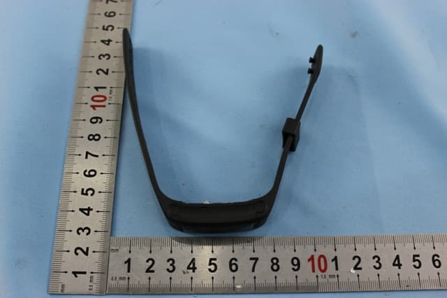
NMTPE961
Nov 11, 2014Activity Tracker
Equipment Class
DTS - Digital Transmission System
NMTRTHN129-01
Sep 12, 20145 Channel Remote RCC-Thermo Sensor
Equipment Class
DSC - Part 15 Security/Remote Control Transmitter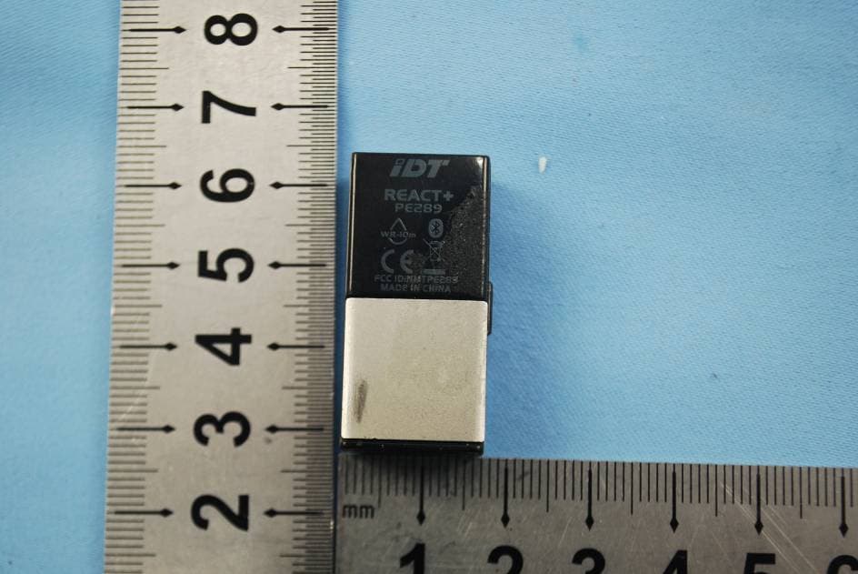
NMTPE289
Aug 21, 20142nd generation activity and sleep monitor wrist device
Equipment Class
DTS - Digital Transmission System