NMTUVN128-01Transmitter Part of UV Sensor
IDT Technology Limited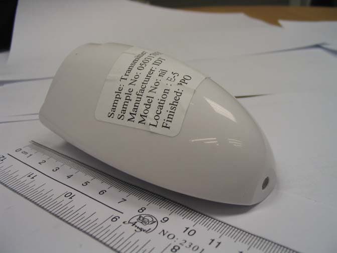
Click to zoom
Application Details
- Equipment Class
- DXX - Part 15 Low Power Communication Device Transmitter
- Date of Grant
- Jun 06, 2005
- Application Purpose
- Original Equipment
- Date of Application
- Jun 06, 2005
- Equipment Note
- Transmitter Part of UV Sensor
- Frequency Range
- 433.92000000 - 433.92000000
- Company
- IDT Technology Limited
- Country
- Hong Kong
Documents & Files
Document Text
Text extracted from the exhibit documents filed with the FCC. Open a document above to read the original.
Users Manual
www.tuv.com Appendix 5 Prüfbericht - Nr.: Test Report No. 14008707 002 Seite 4 von 5 Page 4 of 5
External Photos
www.tuv.com Appendix 3 Prüfbericht - Nr.: Test Report No. 14008707 002 Seite 1 von 2 Page 1 of 2 www.tuv.com Appendix 3 Prüfbericht - Nr.: Test Report No. 14008707 002 Seite 2 von 2 Page 2 of 2
ID Label/Location Info
www.tuv.com Appendix 5 Prüfbericht - Nr.: Test Report No. 14008707 002 Seite 1 von 5 Page 1 of 5
Internal Photos
www.tuv.com Appendix 4 Prüfbericht - Nr.: Test Report No. 14008707 002 Seite 1 von 7 Page 1 of 7 www.tuv.com Appendix 4 Prüfbericht - Nr.: Test Report No. 14008707 002 Seite 2 von 7 Page 2 of 7 www.tuv.com Appendix 4 Prüfbericht - Nr.: Test Report No. 14008707 002 Seite 3 von 7 Page 3 of 7 www.tuv.com Appendix 4 Prüfbericht - Nr.: Test Report No. 14008707 002 Seite 4 von 7 Page 4 of 7 www.tuv.com Appendix 4 Prüfbericht - Nr.: Test Report No. 14008707 002 Seite 5 von 7 Page 5 of 7 www.tuv.com Appendix 4 Prüfbericht - Nr.: Test Report No. 14008707 002 Seite 6 von 7 Page 6 of 7 www.tuv.com Appendix 4 Prüfbericht - Nr.: Test Report No. 14008707 002 Seite 7 von 7 Page 7 of 7
Test Report
www.tuv.com Test Report No.: 14008707 002 Date: 12.05.2005 Page 2 of 13 Test Summary Radiated Emission of Carrier Frequency Result: Pass Spurious Radiated Emissions Result: Pass Bandwidth Measurement Result: Pass www.tuv.com Test Report No.: 14008707 002 Date: 12.05.2005 Page 3 of 13 Contents General Remarks ...................................................................................................4 Complementary Materials.................................................................................................. 4 List of Test and Measurement Instruments.........................................................5 General Product Information ................................................................................6 Product Function and Intended Use................................................................................. 6 Circuit Description .............................................................................................................6 Ratings and System Details .............................................................................................. 6 Independent Operation Modes.......................................................................................... 7 Submitted Documents ....................................................................................................... 7 Related Submittal(s) Grants .............................................................................................. 7 Test Set-up and Operation Mode..........................................................................8 Principle of Configuration Selection ................................................................................ 8 Test Operation and Test Software .................................................................................... 8 Special Accessories and Auxiliary Equipment ............................................................... 8 Countermeasures to achieve EMC Compliance.............................................................. 8 Test Methodology ..................................................................................................9 Radiated Emission ............................................................................................................. 9 Field Strength Calculation ................................................................................................. 9 Test Results .........................................................................................................10 Radiated Emission of Carrier Frequency Section 15.231(b) ..................................... 10 Spurious Radiated Emissions Section 15.231(b)....................................................... 11 Bandwidth Measurement Section 15.231(c) ............................................................... 13 www.tuv.com Test Report No.: 14008707 002 Date: 12.05.2005 Page 4 of 13 General Remarks Complementary Materials All attachments are integral parts of this test report. This applies especially to the following appendix: Appendix 1: Test Results Appendix 2: Test Setup Appendix 3: EUT External Photo Appendix 4: EUT Internal Photo Appendix 5: FCCID Label, Block Diagram, Schematics and User manual. www.tuv.com Test Report No.: 14008707 002 Date: 12.05.2005 Page 5 of 13 List of Test and Measurement Instruments Kind of Equipment Manufacturer Type S/N Test Receiver Rohde & Schwarz ESVS30 842807/009 Biconical Antenna Rohde & Schwarz HK116 841489/015 Log.-Periodic Antenna Rohde & Schwarz HL223 841516/017 Double Ridge Horn Antenna EMCO 3115 9002-3351 Double Ridge Horn Antenna EMCO 3115 9002-3347 Signal Generator Rohde & Schwarz SMY 01 844146/024 Signal Generator Rohde & Schwarz SMY 01 844146/023 Spectrum Analyzer Rohde & Schwarz FSP30 1093.4495K30 www.tuv.com Test Report No.: 14008707 002 Date: 12.05.2005 Page 6 of 13 General Product Information Product Function and Intended Use The equipment under test (EUT) is a remote UV sensor operating at 433.92 MHz. The EUT senses the UV index and then transmits this information to the main unit. A transmitter transmits signal for every 73 seconds, and it activated automatically shall cease transmission within 2 seconds after activation. Hence it operates 50 times per hour. FCC ID NMTUVN128-01 Model Product description UVN128 Remote UV Sensor UVR128 Remote UV Sensor The model UVN128 and UVR128 are same in circuit and PCB design, the difference between them is that UVR128 has LCD display and UVN128 is using LED indicator. Hence, the representative model UVN128 was chosen to perform all testing. Circuit Description The MCU power on the UV sensor circuit, the UV sensor will sense the UV strength and convert to energy, and the photo transistor will biased by this energy, and the output voltage will input to a voltage comparator, then give out an analog voltage, the voltage will feed to the MCU analog port, MCU will based on the voltage to calculate the UV strength by internal A/D converter, then display on the LCD and transmit the data to receiver unit through 433MHz. Ratings and System Details Transmitter Operated Frequency : 433.92 MHz Frequency deviation of Crystal : ± 75KHz Number of channels : 1 Type of antenna : Integral antenna Power supply : Battery operated 3.0V Ports : none Protection Class : III Equipment Class : B www.tuv.com Test Report No.: 14008707 002 Date: 12.05.2005 Page 7 of 13 Independent Operation Modes The basic operation modes are: - Automatically detect UV and transmit signal. - Reset. For further information refer to User Manual Submitted Documents The submitted documents are listed as follow: - Circuit diagram - Block diagram - User manual - FCC ID label Related Submittal(s) Grants This is a single application for certification of the transmitter. www.tuv.com Test Report No.: 14008707 002 Date: 12.05.2005 Page 8 of 13 Test Set-up and Operation Mode Principle of Configuration Selection Emission: The equipment under test (EUT) was configured …
Text truncated - open the document above for the full version.
Test Report
www.tuv.com Appendix 1 Prüfbericht - Nr.: Test Report No. 14008707 002 Seite 1 von 4 Page 1 of 4 Ref -20 dBm 433.917 MHz Att 10 dB 433.917 MHz A 433.917 MHz 1 PK 433.917 MHz MAXH 433.917 MHz Center 433.917 MHz 433.917 MHz Span 200 kHz 433.917 MHz 20 kHz/ 433.917 MHz RBW 3 kHz 433.917 MHz VBW 10 kHz 433.917 MHz * 433.917 MHz SWT 500 ms 433.917 MHz * 433.917 MHz 433.917 MHz 433.917 MHz 433.917 MHz 433.917 MHz 433.917 MHz 433.917 MHz 433.917 MHz 433.917 MHz 433.917 MHz -120 -110 -100 -90 -80 -70 -60 -50 -40 -30 -20 433.917 MHz Marker 2 [T1] -50.20 dBm 433.907800000 MHz Marker 1 [T1] -29.63 dBm 433.917000000 MHz Marker 3 [T1] -49.93 dBm 433.930200000 MHz 2 1 3 MARKER 1 433.917 MHz Date: 30.MAR.2005 10:59:03 -Bandwidth measurement. www.tuv.com Appendix 1 Prüfbericht - Nr.: Test Report No. 14008707 002 Seite 2 von 4 Page 2 of 4 RBW 10 kHz 89.2 ms VBW 30 kHz 89.2 ms CLRWR 89.2 ms A 89.2 ms SGL 89.2 ms Ref -20 dBm 89.2 ms Att 10 dB 89.2 ms Center 433.917 MHz 89.2 ms 10 ms/ 89.2 ms SWT 100 ms 89.2 ms 1 AP 89.2 ms 89.2 ms 89.2 ms 89.2 ms 89.2 ms 89.2 ms 89.2 ms 89.2 ms 89.2 ms 89.2 ms -120 -110 -100 -90 -80 -70 -60 -50 -40 -30 -20 89.2 ms Marker 1 [T1] -44.34 dBm 4.400000 ms Delta 2 [T1] -0.02 dB 89.200000 ms 1 2 DELTA MARKER 2 89.2 ms Date: 30.MAR.2005 11:28:42 - The graph shows the pattern of coding during the signal transmission. - The total “on” time is 100ms. - There are 44 long and 15 short ‘on’ signal. www.tuv.com Appendix 1 Prüfbericht - Nr.: Test Report No. 14008707 002 Seite 3 von 4 Page 3 of 4 Att 10 dB 890 μs A 890 μs RBW 1 MHz 890 μs VBW 1 MHz 890 μs * 890 μs SGL 890 μs MAXH 890 μs Ref 87 dBμV 890 μs Center 433.9 MHz 890 μs 500 μs/ 890 μs SWT 5 ms 890 μs 890 μs 890 μs 890 μs 890 μs 890 μs 890 μs 890 μs 890 μs 890 μs 1 PK 890 μs -10 0 10 20 30 40 50 60 70 80 890 μs Marker 1 [T1] 76.09 dBμV 2.140000 ms Delta 2 [T1] 0.74 dB 890.000000 μs 1 2 DELTA MARKER 2 890 μs Date: 8.APR.2005 17:33:04 - The graph shows the duration of long ‘on’ signal, from marker 1 to marker 2 indicates 890 μ s. www.tuv.com Appendix 1 Prüfbericht - Nr.: Test Report No. 14008707 002 Seite 4 von 4 Page 4 of 4 Att 10 dB 390 μs A 390 μs RBW 1 MHz 390 μs VBW 1 MHz 390 μs * 390 μs SGL 390 μs MAXH 390 μs Ref 87 dBμV 390 μs Center 433.9 MHz 390 μs 500 μs/ 390 μs SWT 5 ms 390 μs 1 PK 390 μs 390 μs 390 μs 390 μs 390 μs 390 μs 390 μs 390 μs 390 μs 390 μs -10 0 10 20 30 40 50 60 70 80 390 μs Marker 1 [T1] 76.47 dBμV 2.040000 ms Delta 2 [T1] 1.07 dB 390.000000 μs 1 2 DELTA MARKER 2 390 μs Date: 8.APR.2005 17:35:21 - The graph shows the duration of short ‘on’ signal, from marker 1 to marker 2 indicates 390 μ s. - Therefore, the total signal ‘on’ time of one successful period is (890μs x 44 ) + (390μs x 15) = 45.01ms . Average factor: 20 log ( 45.01 / 100 ) = -7dB .
Test Setup Photos
www.tuv.com Appendix 2 Prüfbericht - Nr.: Test Report No. 14008707 002 Seite 1 von 1 Page 1 of 1 Set-up for Radiation Emission ( Receiver)
Contact Information
Applicant
Alex Chan(Project Manager)
Technical Contact
T�V Rheinland Hong Kong Ltd.Hugo Wan
[email protected]+852 2192 1000
Unit 8, 25/F., Skyline Tower · Hong Kong · Hong Kong
Test Firm
Hong Kong Productivity CouncilIr Angel Wong Yuen-yee
Technical Specifications
| # | Rule Parts | Frequency Range | Power Output |
|---|---|---|---|
| 1 | 15C | 433.92 MHz - 433.92 MHz | - |
Other Applications from IDT Technology Limited

NMTBAR228-01
Dec 03, 2015Weather+BLE Connected Weather Station
Equipment Class
DTS - Digital Transmission System
NMTRTGN130A-01
Sep 10, 2015Outdoor sensor
Equipment Class
DSC - Part 15 Security/Remote Control Transmitter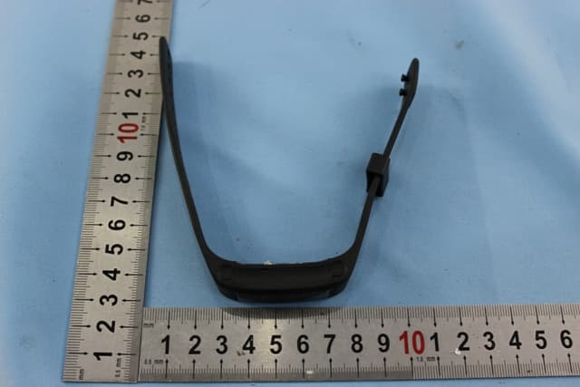
NMTPE961
Nov 11, 2014Activity Tracker
Equipment Class
DTS - Digital Transmission System
NMTRTHN129-01
Sep 12, 20145 Channel Remote RCC-Thermo Sensor
Equipment Class
DSC - Part 15 Security/Remote Control Transmitter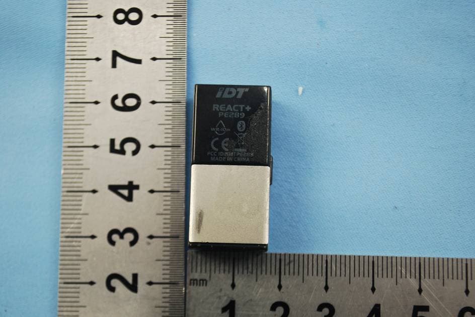
NMTPE289
Aug 21, 20142nd generation activity and sleep monitor wrist device
Equipment Class
DTS - Digital Transmission System