NR3AIM2MBAUTOMATED FUEL MANAGEMENT SYSTEM
Syn Tech Systems Inc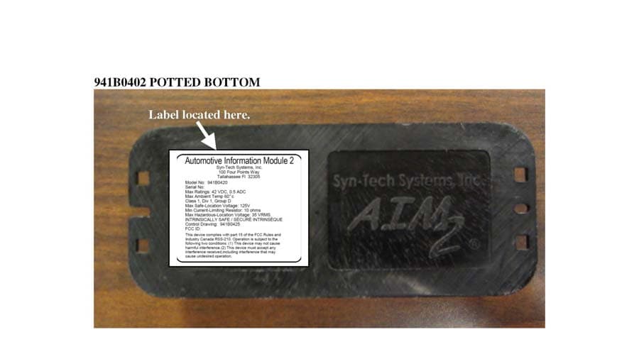
Click to zoom
Application Details
- Equipment Class
- DXX - Part 15 Low Power Communication Device Transmitter
- Date of Grant
- Dec 12, 2005
- Application Purpose
- Original Equipment
- Date of Application
- Dec 12, 2005
- Equipment Note
- AUTOMATED FUEL MANAGEMENT SYSTEM
- Frequency Range
- 902.66666000 - 927.66666000
- Company
- Syn Tech Systems Inc
- Country
- United States
Documents & Files
Document Text
Text extracted from the exhibit documents filed with the FCC. Open a document above to read the original.
Users Manual
AIM2 INSTALLATION INSTRUCTIONS Syn-Tech Systems, Inc. 11/30/2005 2 WARNING: AIM2 equipment is only intended to be used with the AIM2 system. Do not connect any AIM2 part to any non-AIM2 part unless specified in these instructions. Changes or modifications not expressly approved by the manufacturer could void the user's authority to operate this device. NOTE: This equipment has been tested and found to comply with the limits for a Class A digital device, pursuant to part 15 of the FCC Rules. These limits are designed to provide reasonable protection against harmful interference when the equipment is operated in a commercial environment. This equipment generates, uses, and can radiate radio frequency energy and, if not installed and used in accordance with the instruction manual, may cause harmful interference to radio communications. Operation of this equipment in a residential area is likely to cause harmful interference in which case the user will be required to correct the interference at his own expense. This device complies with part 15 of the FCC rules. Operation is subject to the following two conditions: (1) this device may not cause harmful interference, and (2) this device must accept any interference received, including interference that may cause undesired operation. 3 AIM2 vehicle installations for vehicles using the OBD port. Step 1: Select mounting location for the AIM2 Main Module. Recommended locations are under the dash or under the seat that is on the same side of the vehicle as the fuel tank’s filler neck. Keep in mind the distance from the power source and grounding requirements in relation to the mounting location. Note: The AIM2 Main Module should be mounted out of harms way but, accessible for service or troubleshooting. Warning: The AIM2 Main Module uses Radio Frequency technology to communicate with the fuel island. Do not mount this unit in steel or fiberglass enclosures. This type of install may prevent your system from working properly. Please contact FuelMaster for installation recommendations.1-800-888-9136 Step 2: Connect the main ground lug to a good chassis ground. For the main ground lug, use 12 gauge wire and the provided 12 gauge ring terminal. Note: For installations in Canada, two 12 gauge ground wires must be used. Step 3: If necessary, drill a hole large enough for the connector on the RFID Extension Cable to fit through, usually in a wire chase. Step 4: Plug one end of the RFID Extension Cable into one of the AIM2 Main Module’s Tank Ring Ports (Fig. 1). Step 5: Place the provided rubber grommet around the RFID Extension Cable and pass the cable through the drilled hole, fitting the grommet securely in the opening. Step 6: Route the RFID Extension Cable to the top of the fuel tank filler neck. If routing outside the vehicle, make sure to use the protective loom for the entire length of the pull under the vehicle. Loosely zip tie the loom and cable. Make sure to leave room to adjust slack. Step 7: Drill hole large enough for the connector on the Filler Neck Ring in the housing around the filler neck where the gas cap is located. Step 8: Place the Filler Neck Ring around the filler neck under the gas cap and pass the Filler Neck Ring cable (with grommet) through the drilled hole and secure grommet in opening. 4 Step 9: Attach RFID Interface Module to Filler Neck Ring cable and RFID Extension Cable and zip tie in place. Step 10: From the mounting location of the AIM2 Main Module, pull the slack from the RFID Extension Cable so that it is snug. Step 11: Tighten all zip ties and clip the extra plastic with a pair of wire snips and seal both drilled holes with silicon. Step 12: Coil any leftover slack from the RFID Extension Cable secure so it is out of the way. Step 13: Connect OBD interface cable (KSM-DEV052305, KSM-2538 or KSM-2539) to the Vehicle’s OBD connector and AIM2 Main Module via the OBD Port (Fig. 1) and secure cable so that it is out of the driver’s way. Step 14: Start vehicle, AIM2 Main Module status lights should turn on. 5 AIM2 vehicle installations for vehicles using the Vehicle Speed Sensor (odometer) output. Step 1: Select mounting location for the AIM2 Main Module. Recommended locations are under the dash or under the seat that is on the same side of the vehicle as the fuel tank’s filler neck. Keep in mind the distance from the power source and grounding requirements in relation to the mounting location. Note: The AIM2 Main Module should be mounted out of harms way but, accessible for service or troubleshooting. Warning: The AIM2 Main Module uses Radio Frequency technology to communicate with the fuel island. Do not mount this unit in steel or fiberglass enclosures. This type of install may prevent your system from working properly. Please contact FuelMaster for installation recommendations.1-800-888-9136 Step 2: Connect the Analog Speed Sensor Cable Assembly ground wires as well as the main ground lug to a good chassis ground. For the main ground lug, use 12 gauge wire and the provided 12 gauge ring terminal. Note: Do not lengthen these wires. It may be necessary to remove paint from painted surfaces to achieve a proper ground. For installations in Canada, 2 12 gauge ground wires must be used. Do not connect the AIM2 at this time. Step 3: Locate a constant +12VDC supply with the vehicle key in the “off “ position. This will provide power to the “RED” lead of the Analog Speed Sensor Cable Assembly to operate the AIM2 Main Module. Step 4: Locate a switched +12VDC supply that is present only when the vehicle key is in the “ON” position. Connect the “BROWN” wire of the Analog Speed Sensor Cable Assembly to this source. This signal is required to indicate the status of the vehicle on or off. Step 5: Locate and terminate the GREEN wire of the Analog Speed Sensor Cable Assembly to the VSS (vehicle speed sensor) output. This signal can be found at the transmission speed sensor after the vehicles computer module. Note: Vehicle applications ma…
Text truncated - open the document above for the full version.
External Photos
SYN-TECH SYSTEMS, INC. FCC ID: NR3AIM2MB EXTERNAL PHOTOS
ID Label/Location Info
941B0402 POTTED BOTTOM FMU 3500 WITH 941B0404 MOUNTED INSIDE Label located on side. Label located here.
ID Label/Location Info
NOTE: 1 INTERPRET DRAWING IN ACCORDANCE WITH STANDARDS PRESCRIBED IN DOD-STD-100C2 MATERIAL: LABEL - PIGMENTED ELASTOMERIC SHEETING MATERIAL (POLYESTER OR VINYL) ADHESIVE BACKING - SCOTCH 3M #9471 HIGH STRENGTH ACRYLIC LAMINATING ADHESIVE PROTECTED BY PEEL OFF LINER COLORS: A - BLACK, COLOR #17038 OF FED-STD-595 B - BACKGROUND - NEUTRAL GRAY C - PART TO BE UNDER PRINTED3 PART TO BE SERIALIZED BY HOT STAMPING INITIAL RELEASE 04-10-12 SFP DATE APPROVED DESCRIPTION REV ZONE REVISIONS - 1 2 3 4 5 6 7 8 B A C DC B A R E V S H D W G N O . D 1 9 4 1 B 0 4 0 6 THIS DRAWING IS THE PROPERTY OF SYN-TECH SYSTEMS, INCIT IS LOANED UPON THE CONDITION THAT IT SHALL NOT BECOPIED OR REPRODUCED IN ANY MANNER, OR BE SUBMITTEDTO OTHERS WITHOUT OUR WRITTEN CONSENT, OR USED INANY WAY DETRIMENTAL TO THE INTEREST OF THIS COMPANY,AND SHALL BE RETURNED UPON DEMAND APPLICATION 912B0400 NEXT ASSY USED ON DO N0T SCALE DRAWING MATERIAL CONTRACT NO. DRAWN CHECKED ENGR RELEASED DESIGN ACTIVITY APVLGOVT ACTIVITY APVL DATE E BUDZYNA 04-10-12 DATEDATEDATEDATEDATE S POLLOCK S POLLOCK SYN-TECH SYSTEMS, INC LABEL, AIM 2, ETL TALLAHASSEE, FLORIDA SIZE CODE IDENT NO. SCALE 2 / 1 SHEET 1 OF 1 D 56672 941B0406 REV D UNLESS OTHERWISE SPECIFIED DIMENSIONS ARE IN INCHES TOLERANCES ON FRACTIONS +/- ANGLES +/- 1 2 2 PL DEC +/- 3 PL DEC +/- .06 .03 PART NO. 941B0406-1 04-10-1204-10-12 FULL SIZE Automotive Information Module 2 Syn-Tech Systems, Inc. 100 Four Points Way Tallahassee Fl 32305 Model No: 941B0420 Serial No: Max Ratings: 42 VDC, 0.5 ADCMax Ambient Temp 60 c Class 1, Div 1, Group DMax Safe-Location Voltage: 125V Min Current-Limiting Resistor: 10 ohms Max Hazardous-Location Voltage: 35 VRMS 1.565 3 .045 TYP INTRINSICALLY SAFE / SECURE INTRINSEQUE Control Drawing: 941B0425 FCC ID: NR3AIM2MB .094 1.815 R.09 .045 TYP CHANGED LAST PARAGRAPH ON LABEL 05-10-05 ESB B CH NOTE 2B,ADDED NOTE 2C,CH NOTE 3 (DELETED LAMINATE COATING)ADDED ", and " BEFORE (2) 05-10-20 ESB C IC: 4479A-AIM2MB This device complies with part 15 of the FCC Rules and Industry Canada RSS-210. Operation is subject to the following two conditions: (1) This device may not cause harmful interference,and (2) This device must accept anyinterference received,including interference that may cause undesired operation. .040 TYP Automotive Information Module 2 Syn-Tech Systems, Inc. 100 Four Points Way Tallahassee Fl 32305 Model No: 941B0420 Serial No: Max Ratings: 42 VDC, 0.5 ADCMax Ambient Temp 60 c Class 1, Div 1, Group DMax Safe-Location Voltage: 125V Min Current-Limiting Resistor: 10 ohmsMax Hazardous-Location Voltage: 35 VRMS INTRINSICALLY SAFE / SECURE INTRINSEQUE Control Drawing: 941B0425 FCC ID: NR3AIM2MBIC: 4479A-AIM2MB This device complies with part 15 of the FCC Rules and Industry Canada RSS-210. Operation is subject to the following two conditions: (1) This device may not cause harmful interference,and (2) This device must accept anyinterference received,including interference that may cause undesired operation. ADD FCC ID (NR3AIM2MB),ADD IC:4479A-AIM2FMU 05-11-10 ESB D CH SPACING & LETTER SIZE TO FIT OUTLINE
Internal Photos
SYN-TECH SYSTEMS, INC. FCC ID: NR3AIM2MB INTERNAL PHOTOS
Operational Description
DESCRIPTION OF THE SYSTEM The AIM2 system is an automated vehicle fueling system. It consists of a fixed unit (FMU 3500) mounted near the fuel dispenser, and a vehicle unit (941B0400) mounted in a vehicle. Instead of the user using a key or access number at the fixed unit to get fuel, the vehicle-mounted module uses 2-way communication for authorization to fuel. There are two units to be tested. One is a Fixed mounted unit (FMU Radio Board (FRB; 941B0404)) that plugs into a PCB mounted inside the FMU 3500. This fixed unit has has 2 radios on it for diversity. The radios are connected to two Maxrad MUF9000 antennas mounted on the outside of the FMU 3500. The mobile unit to be tested (Vehicle Main Board; VMB; 941B0402) is mounted in the vehicle. It has one radio on it. It has a custom printed circuit antenna. There are 25 channels the radios use, starting at 902.6666 MHz and ending at 927.6666 MHz. The channels are in 1 MHz increments. During normal operation, the FRB upon bootup will choose a channel based on the lowest noise level. Once that channel is selected, it transmits RF messages to any potential VMB’s in the area. It almost continuously transmits serving as a beacon to any VMB’s so they can pick up on the signal quickly. Meanwhile, the VMB is continuously sampling each channel looking for any messages from an FRB. The VMB does not transmit until it finds an FRB. Once the VMB finds an FRB, it locks the channel and continues 2-way communication with the FRB until the VMB leaves the area or times out. This application is for only the mobile transmitter.
Test Report
TIMCO ENGINEERING INC. 849 NW State Road 45 Newberry, Florida 32669 http://www.timcoengr.com 888.472.2424 F 352.472.2030 email: [email protected] APPLICANT: SYN-TECH SYSTEMS, INC. Test Report Product Name: AUTOMATED FUEL MANAGEMENT SYSTEM FCC ID: NR3AIM2MB Applicant: SYN-TECH SYSTEMS, INC. 100 FOUR POINTS WAY TALLAHASSEE FLORIDA 32305 USA Date Receipt: 9/27/2005 Date Tested: 10/24/2005 FCC ID: NR3AIM2MB REPORT #: S\SYN\2018AUT5\2018AUT5TestReport.doc COVER SHEET TIMCO ENGINEERING INC. 849 NW State Road 45 Newberry, Florida 32669 http://www.timcoengr.com 8.472.2424 F 352.472.2030 email: [email protected] 88 APPLICANT: SYN-TECH SYSTEMS, INC. FCC ID: NR3AIM2MB REPORT #: S\SYN\2018AUT5\2018AUT5TestReport.doc TABLE OF CONTENTS APPLICANT: SYN-TECH SYSTEMS, INC. FCC ID: NR3AIM2MB TABLE OF CONTENTS TEST REPORT CONTAINING: PAGE 1...........TEST EQUIPMENT LIST PAGE 2...........TEST PROCEDURE PAGE 3-6.........RADIATION INTERFERENCE TEST DATA PAGE 7-8.........OCCUPIED BANDWIDTH PAGE 9...........POWERLINE CONDUCTED PAGE 10-11.......POWERLINE CONDUCTED PLOTS EXHIBIT INCLUDED: REQUEST FOR CONFIDENTIALITY LETTER BLOCK DIAGRAM SCHEMATIC USERS MANUAL LABEL SAMPLE LABEL LOCATION EXTERNAL PHOTOGRAPHS INTERNAL PHOTOGRAPHS OPERATIONAL DESCRIPTION TEST SET UP PHOTOGRAPHS TIMCO ENGINEERING INC. 849 NW State Road 45 Newberry, Florida 32669 http://www.timcoengr.com 888.472.2424 F 352.472.2030 email: [email protected] APPLICANT: SYN-TECH SYSTEMS, INC. EMC Equipment List Device Manufacturer Model Serial Number Cal/Char Date Due Date 3/10-Meter OATS TEI N/A N/A Listed 3/27/04 3/26/07 3-Meter OATS TEI N/A N/A Listed 1/13/03 1/12/06 Biconnical Antenna Eaton 94455-1 1057 CAL 3/18/03 3/18/05 Biconnical Antenna Eaton 94455-1 1096 CAL 8/17/04 8/17/06 Biconnical Antenna Electro- Metrics BIA-25 1171 CAL 4/29/05 4/29/07 Blue Tower Quasi-Peak Adapter HP 85650A 2811A01279 CAL 4/13/05 4/13/07 Blue Tower RF Preselector HP 85685A 2926A00983 CAL 8/3/05 8/3/07 Blue Tower Spectrum Analyzer HP 8568B 2928A04729 2848A18049 CAL 4/13/05 4/13/07 LISN Electro- Metrics ANS-25/2 2604 CAL 8/27/04 8/27/06 LISN Electro- Metrics EM-7820 2682 CAL 4/28/05 4/28/07 Log- Periodic Antenna Eaton 96005 1243 CAL 5/8/03 5/8/05 FCC ID: NR3AIM2MB REPORT #: S\SYN\2018AUT5\2018AUT5TestReport.doc Page 1 of 10 TIMCO ENGINEERING INC. 849 NW State Road 45 Newberry, Florida 32669 http://www.timcoengr.com 888.472.2424 F 352.472.2030 email: [email protected] APPLICANT: SYN-TECH SYSTEMS, INC. TEST PROCEDURE GENERAL: This report shall NOT be reproduced except in full without the written approval of TIMCO ENGINEERING, INC. The UUT was transmitting a test signal during the testing. RADIATION INTERFERENCE: The test procedure used was ANSI STANDARD C63.4-2003 using a HEWLETT PACKARD spectrum analyzer with a pre-selector. The analyzer was calibrated in dB above a microvolt at the output of the antenna. The resolution bandwidth was 100KHz and the video bandwidth was 300KHz up to 1.0GHz and 1.0MHz with a video BW of 3.0MHz above 1.0GHz. The ambient temperature of the UUT was 74.3oF with a humidity of 69%. FORMULA OF CONVERSION FACTORS: The Field Strength at 3m was established by adding the meter reading of the spectrum analyzer (which is set to read in units of dBuV) to the antenna correction factor supplied by the antenna manufacturer. The antenna correction factors are stated in terms of dB. The gain of the Preselector was accounted for in the Spectrum Analyzer Meter Reading. Example: Freq (MHz) METER READING + ACF = FS 33 20 dBuV + 10.36 dB = 30.36 dBuV/m @ 3m POWER LINE CONDUCTED INTERFERENCE: The procedure used was ANSI STANDARD C63.4- 2003 using a 50uH LISN. Both lines were observed. The bandwidth of the spectrum analyzer was 10kHz with an appropriate sweep speed. The ambient temperature of the UUT was 74.3oF with a humidity of 69%. ANSI STANDARD C63.4-2003 10.1.7 MEASUREMENT PROCEDURES: The UUT was placed on a table 80 cm high and with dimensions of 1m by 1.5m. The UUT was placed in the center of the table (1.5m side). The table used for radiated measurements is capable of continuous rotation. When an emission was found, the table was rotated to produce the maximum signal strength. At this point, the antenna was raised and lowered from 1m to 4m. The antenna was placed in both the horizontal and vertical planes. The situation was similar for the conducted measurement except that the table did not rotate. The EUT was setup as described in ANSIC63.4-2003 with the EUT 40 cm from the vertical ground wall. FCC ID: NR3AIM2MB REPORT #: S\SYN\2018AUT5\2018AUT5TestReport.doc Page 2 of 10 TIMCO ENGINEERING INC. 849 NW State Road 45 Newberry, Florida 32669 http://www.timcoengr.com 888.472.2424 F 352.472.2030 email: [email protected] APPLICANT: SYN-TECH SYSTEMS, INC. APPLICANT: SYN-TECH SYSTEMS, INC. FCC ID: NR3AIM2MB NAME OF TEST: RADIATION INTERFERENCE RULES PART NUMBER: 15.249, 15.209 REQUIREMENTS: FIELD STRENGTH FIELD STRENGTH S15.209 of Fundamental: of Harmonics 30 - 88 MHz 40 dBuV/m @3M 902-928 MHZ 88 - 216 MHz 43.5 2.4-2.4835 GHz 216 - 960 MHz 46 94 dBuV/m @3m 54 dBuV/m @3m ABOVE 960 MHz 54dBuV/m EMISSIONS RADIATED OUTSIDE OF THE SPECIFIED FREQUENCY BANDS, EXCEPT FOR HARMONICS, SHALL BE ATTENUATED BY AT LEAST 50 dB BELOW THE LEVEL OF THE FUNDAMENTAL OR TO THE GENERAL RADIATED EMISSION LIMITS IN 15.209, WHICHEVER IS THE LESSER ATTENUATION. TEST RESULTS: This unit DOES meet the FCC requirements. TEST DATA: Tuned Frequency MHz Emission Frequency MHz Meter Reading dBuV Ant. Polarity Coax Loss dB Correction Factor dB Field Strength dBuV/m Mar gin dB 902.7 902.66 67.3 V 1.95 22.33 91.58 2.42 902.7 902.66 68.4 H 1.95 23.3 93.65 0.35 902.7 1,805.32 15.6 H 2.74 30.03 48.37 5.63 902.7 1,805.32 16.5 V 2.74 30.03 49.27 4.73 902.7 2,707.98 12.9 H 3.4 32.85 49.15 4.85 902.7 2,707.98 13.2 V 3.4 32.85 49.45 4.55 914.7 914.66 66.3 V 1.97 22.54 90.81 3.19 914.7 914.66 67.1 H 1.97 23.39 92.46 1.54 914.7 1,829.32 14.9 H 2.76 30.18 47.84 6.16 914.7 1,829.32 16.5 V 2.76 30.18 49.44 4.56 914.7 2,…
Text truncated - open the document above for the full version.
Test Setup Photos
SYN-TECH SYSTEMS, INC. FCC ID: NR3AIM2MB TEST SET UP PHOTOS RADIATED EMISSIONS TEST SET UP POWERLINE CONDUCTED EMISSIONS TEST SET UP
Contact Information
Applicant
Joe Hagan
850-878-2558Fax: 850-877-9327
Test Firm
Timco Engineering, Inc.S Sanders
Technical Specifications
| # | Rule Parts | Frequency Range | Power Output |
|---|---|---|---|
| 1 | 15C | 902.66666 MHz - 927.66666 MHz | - |
Other Applications from Syn Tech Systems Inc
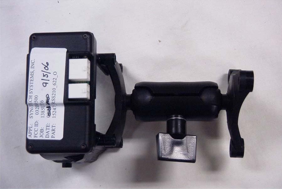
NR3-032B0500
Apr 15, 2007TRUCK CRADLE- BT
Equipment Class
DSS - Part 15 Spread Spectrum Transmitter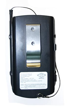
NR3-032B0100
Nov 01, 2006PDA WITH BLUETOOTH MODULE
Equipment Class
DSS - Part 15 Spread Spectrum Transmitter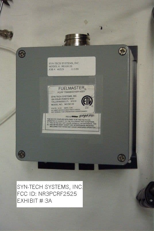
NR3PCRF2525
Mar 02, 2000Fueling System
Equipment Class
DSS - Part 15 Spread Spectrum Transmitter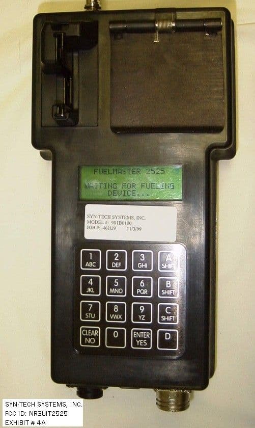
NR3UIT2525
Feb 24, 2000Automated Fuel System
Equipment Class
DSS - Part 15 Spread Spectrum Transmitter