NRA-002TER04RXPool Monitor Alarm Receiver
Terrapin Communications Inc.
Click to zoom
Application Details
- Equipment Class
- CYY - Communications Receiver used w/Pt 15 Transmitter
- Date of Grant
- May 25, 2004
- Application Purpose
- Original Equipment
- Date of Application
- May 25, 2004
- Equipment Note
- Pool Monitor Alarm Receiver
- Frequency Range
- 318.05000000 - 318.05000000
- Company
- Terrapin Communications Inc.
- Country
- Canada
Documents & Files
Document Text
Text extracted from the exhibit documents filed with the FCC. Open a document above to read the original.
Users Manual
Safety Turtle R User Guide Safety Turtle 2 User Guide Keep page 3 open when reading these operating instructions. C A (front) A (rear) D E B K J F G H I L Safety Turtle 3 User Guide Safety Turtle 4 User Guide General Product Description (Refer to Page 3) Base Station Package ABase Station BBaby Turtle receptacle CMoon-shaped button DOn light (green) ETest light (amber) FBasket GPlug in AC adapter HPower socket Turtle Wristband Package ITu rtle JLocking buckle KKey for locking buckle LBaby Turtle plug Safety Turtle 5 User Guide IMPORTANT Safety Turtleis not a substitute for diligent supervision or for pool access barriers.It has been designed as a “last line of defense” to help prevent drowning of young children. Failure to observe any of the following may delay or prevent alarming when the Turtle is immersed: ➤Do not use in sea water or in pools with a salt concentration of more than 4000 ppm. ➤Attach the Turtle wristband to the wrist only. ➤Do not cover the Turtle wristband with a jacket or other clothing. ➤Immediately remove any food, beverage, or other material that enters the space between the top and bottom Turtle shells. A residue such as milk that has been allowed to dry can prevent alarming when the Turtle is immersed. Read all instructions. Carefully follow Initial Setup and Testing instructions before using Safety Turtle. Observe the following precautions: ➤Your Turtles must all be of the same color as the Baby Turtle plug inserted into the Base Station. ➤The Base Station is for indoor use only. Locate the Base Station where the alarm can be heard. ➤Do not locate the Base Station where it can accidentally be unplugged or power from the outlet switched off.The Base Station will not sound the alarm if not plugged in to a live AC outlet. ➤Use only the Terrapin AC adapter provided, plugged into a matching electrical outlet.Terrapin adaptors operate at one AC voltage only. ➤Follow the Initial Setup and Testinginstructions to verify that the alarm sounds when each of your Turtles is immersed.Test all areas of your pool. Re-verify if the Base Station is relocated. Safety Turtle 6 User Guide ➤Always test your Turtles before using.Towel dry edges of Turtle after removing from water. ➤Attach the Turtle wristband securely to your child’s wrist, so it cannot slip over the hand.Dots on buckle must align exactly.Keep the buckle key out of children’s reach. ➤Minimize wear of locking buckle by turning key in one direction only. ➤Remove the Turtle wristband while bathing your child or playing with your child in the pool.Don’t forget to put the wristband back on. Never unplug the Base Station. ➤The alarm is very loud. Avoid prolonged exposure to prevent possible hearing damage. ➤Do not use Safety Turtleif the Base Station is emitting a rapid beeping sound. Refer to Troubleshooting. ➤Follow the instructions in Care of your Safety Turtle. CONGRATULATIONS Congratulations on purchasing Safety Turtle.This state-of-the-art product provides a “last line of defense” for you in protecting children in your care from swimming pool accidents. It is not a substitute for diligent supervision or for pool access barriers. The Turtle wristband has been designed to be pleasing to young children, so they will want to wear it.But the Turtle wristband is not a toy; keep out of children’s reach when not being worn. Please complete and return the accompanying registration card. This allows us to forward further information about the safest use of this product. Safety Turtle 7 User Guide Federal Communications Commission (FCC) Notice This device complies with FCC Part 15 Rules and Industry Canada RSS 210 Issue 2 Regulations. Operation is subject to the following two conditions: ➤this device may not cause harmful interference; and, ➤this device must accept any interference received, including interference that may cause undesired operation. Changes or modifications not expressly approved by Terrapin Communications Inc. could void the user’s authority to operate the equipment. Your Safety Turtle Alarm System The Safety Turtlealarm system is designed as a “last line of defense” to help prevent drowning of young children. It is not a substitute for diligent supervision or for pool access barriers. Please take the time to read these instructions carefully before using the product. Ensure that you pay particular attention to the instructions related to testing. Your Safety Turtlealarm system consists of a Base Station, one or more Turtle wristbands of the same color and (optionally) a carrying bag/battery pack. ➤The Base Station and each Turtle wristband are purchased individually. ➤The Base Station package includes an AC adapter and this User Guide. ➤The Turtle wristband package includes a Baby Turtle plug and a 1/4 inch Allen key for the locking buckle. ➤A Baby Turtle plug must be inserted into the Base Station. ➤Turtles come in the following colors: green, blue, red, yellow, orange and purple. Only Turtles of the same color as the Baby Turtle can trigger an alarm. Safety Turtle 8 User Guide ➤The maximum operating separation (range) between the Base Station and Turtle is typically 100 feet (30 meters). This will vary from home to home due to differences in blockage and radio interference. ➤If you purchase more than one Turtle wristband, keep the extra Baby Turtle plug(s) and key(s) as spares. The Safety Turtlealarm system has two modes of operation:Active Modeand Test Mode.It also has a Fault Conditionto alert you if the system detects a problem with one of its components. ➤ACTIVE MODEis the normal mode for Safety Turtle.The green light is on and the amber light is off. If a Turtle of the same color as the Baby Turtle plug is immersed in water, a loud siren sound will be produced and the amber light will flash on and off. The alarm volume can be reduced by pressing the moon-shaped button on the Base Station.The alarm will then stop completely a few seconds after the Turtle has been towel dried. ➤TEST MODEis provided for co…
Text truncated - open the document above for the full version.
Block Diagram
Square Peg Communications Inc. 3701 Carling Avenue, Building 6 Box 11490, Station H, Ontario, Canada K2H 8S2 Phone: (613) 820-7817 Fax:(613) 993-3122 318 SAFETY TURTLE™ RECEIVER DESCRIPTION REVISION 1.0 2.0 DATE 98/09/08 04/04/04 This document contains information proprietary to Square Peg Communications Inc. Use or reproduction without the express written permission of Square Peg Communications Inc is prohibited. TABLE OF CONTENTS Safety Turtle™ i Receiver Description 5/26/2004 CONTENTS 1. INTRODUCTION .................................................................................................................................... 1-1 2. DEVICE OPERATION............................................................................................................................ 2-1 3. CIRCUIT DESCRIPTION ....................................................................................................................... 3-2 3.1 POWER SUPPLY................................................................................................................................... 3-3 3.2 ANTENNA............................................................................................................................................. 3-3 3.3 RECEIVER............................................................................................................................................ 3-3 3.4 CONTROLLER....................................................................................................................................... 3-3 4. REGULATORY COMPLIANCE............................................................................................................. 4-4 FIGURES Figure 1 Receiver Block Diagram .................................................................................................................. 3-2 INTRODUCTION Safety Turtle™ 2-1 Receiver Description 5/26/2004 1. INTRODUCTION The mission of the Safety Turtle™ system is to alert a supervising adult when a child enters a swimming pool, lake, or other body of water unnoticed, and thus to reduce a significant cause of death and injury among young children. The system consists of the following elements: • a transmitter, which is worn by the person being monitored; • a receiver, which alerts the supervisor when the remote unit detects immersion in water; • a radio link, by which the transmitter signals immersion to the receiver. This document provides a detailed description of the operation of the Safety Turtle™ receiver. 2. DEVICE OPERATION The transmitter emits a coded radio signal when immersed in water. The signal is detected by the receiver, which generates an audio alarm. The receiver is line-powered via a wall-mount low-voltage transformer and employs an internal monopole antenna. There are no adjustments or user-serviceable parts. The case is not intended to be opened by the user. The user interface consists of two LEDs, a momentary-contact switch, and a piezoelectric audio alarm. In addition, a socket on the front panel accepts a coding plug that selects the transmitted code to which the receiver will respond. The plug is colour- coded to correspond to the colour of the matching transmitter. CIRCUIT DESCRIPTION Safety Turtle™ 3-2 Receiver Description 5/26/2004 3. CIRCUIT DESCRIPTION As shown in Figure 1, the receiver consists of the following elements: • Power supply • Antenna • Input filter • Preamplifier • Local oscillator • Mixer/IF processor • Controller Figure 1 Receiver Block Diagram MAX147 3 Receive r LN A Mixer/IF Processor Controller PIC16C73A 318.05 MHz Code Selection On Tes t Test/Rese t Alarm Powe r Supply 9 VAC 20 MHz SYNTH CIRCUIT DESCRIPTION Safety Turtle™ 3-3 Receiver Description 5/26/2004 3.1 Power Supply The power supply converts 9 VAC from a wall-mount transformer to +5 VDC regulated for the electronics and to +12 VDC unregulated to drive the audio alarm. 3.2 Antenna The antenna is a monopole approximately 8.5" in length. It is contained within the receiver case and is directly attached to the receiver PCB. 3.3 Receiver The MAX1473 is a fully integrated low-power CMOS super-heterodyne ASK receiver. The chip consists of a low-noise amplifier (LNA), a differential image-rejection mixer, an on chip phase-locked-loop (PLL) with integrated voltage-controlled oscillator (VCO), a 10.7 MHz IF limiting amplifier with received-signal-strength indicator (RSSI) and an analog base band data recovery circuit. 3.4 Controller The controller processes the base band output from the IF processor to detect the presence of the transmitted code. A coding plug corresponding to the associated transmitter applies a pattern of connections to a set of pins to select the code to be recognized. When the selected code is detected, the receiver drives a piezoelectric bender to generate an audible alarm. A pushbutton switch allows the user to acknowledge the alarm, and to place the unit in a test mode where the alarm volume is temporarily reduced. Two LEDs indicate the presence of main power and whether the unit is in test mode. The controller employs a microprocessor with an internal clock oscillator. The clock rate is fixed at 20 MHz by a ceramic resonator external to the processor. REGULATORY COMPLIANCE Safety Turtle™ 4-4 Receiver Description 5/26/2004 4. REGULATORY COMPLIANCE The receiver has been designed and tested to comply with the following regulations: • USA: CFR Title 47, Part 15, Subpart B • Canada: RSS-210
ID Label/Location Info
b a s e s t a t i o n l a b e l WARNING - Safety Turtle™ is not a substitute for any other water safety precautions. Read instructions carefully before use. Call 1-800-368-8121 for guidance. ATTENTION - Le Safety Turtle MC n’est pas conçu pour remplacer les autres mesures de sécurité aquatique. Lisez attentivement les instructions avant l’utilisation. Composez le 1-800-368-8121 pour obtenir des conseils. ADVERTENCIA - Safety Turtle™ no sustituye ninguna otra precaución o medida de seguridad. Lea las instrucciones cuidadosamente antes de usar. Llame 1-800-368-8121 para cualquier consulta. OPERATION IS SUBJECT TO THE FOLLOWING T WO RULES: (1) this device may not cause harmful interference, and (2) this device must accept any interference received, including interference that may cause undeired operation. MODEL #: B102 Made in China FOR INDOOR USE ONLY POUR USAGE INTÉRIEUR SEULEMENT PARA USO DENTRO DE CASA US Patent 6,157,303 Ottawa, Canada ww w.sa fetyturtle.com Terrapin Communications Ltd. Safety Turtle Product Labels 04/04 Reg. Des. US 430,546 CA 85384 FCC ID NRA-002TER04RX CANADA 31901021221A COLOUR: PURPLE PANTONE # 2695 C
Operational Description
Square Peg Communications Inc. 3701 Carling Avenue, Building 6 Box 11490, Station H, Ontario, Canada K2H 8S2 Phone: (613) 820-7817 Fax:(613) 993-3122 318 SAFETY TURTLE™ RECEIVER DESCRIPTION REVISION 1.0 2.0 DATE 98/09/08 04/04/04 This document contains information proprietary to Square Peg Communications Inc. Use or reproduction without the express written permission of Square Peg Communications Inc is prohibited. TABLE OF CONTENTS Safety Turtle™ i Receiver Description 5/26/2004 CONTENTS 1. INTRODUCTION .................................................................................................................................... 1-1 2. DEVICE OPERATION............................................................................................................................ 2-1 3. CIRCUIT DESCRIPTION ....................................................................................................................... 3-2 3.1 POWER SUPPLY................................................................................................................................... 3-3 3.2 ANTENNA............................................................................................................................................. 3-3 3.3 RECEIVER............................................................................................................................................ 3-3 3.4 CONTROLLER....................................................................................................................................... 3-3 4. REGULATORY COMPLIANCE............................................................................................................. 4-4 FIGURES Figure 1 Receiver Block Diagram .................................................................................................................. 3-2 INTRODUCTION Safety Turtle™ 2-1 Receiver Description 5/26/2004 1. INTRODUCTION The mission of the Safety Turtle™ system is to alert a supervising adult when a child enters a swimming pool, lake, or other body of water unnoticed, and thus to reduce a significant cause of death and injury among young children. The system consists of the following elements: • a transmitter, which is worn by the person being monitored; • a receiver, which alerts the supervisor when the remote unit detects immersion in water; • a radio link, by which the transmitter signals immersion to the receiver. This document provides a detailed description of the operation of the Safety Turtle™ receiver. 2. DEVICE OPERATION The transmitter emits a coded radio signal when immersed in water. The signal is detected by the receiver, which generates an audio alarm. The receiver is line-powered via a wall-mount low-voltage transformer and employs an internal monopole antenna. There are no adjustments or user-serviceable parts. The case is not intended to be opened by the user. The user interface consists of two LEDs, a momentary-contact switch, and a piezoelectric audio alarm. In addition, a socket on the front panel accepts a coding plug that selects the transmitted code to which the receiver will respond. The plug is colour- coded to correspond to the colour of the matching transmitter. CIRCUIT DESCRIPTION Safety Turtle™ 3-2 Receiver Description 5/26/2004 3. CIRCUIT DESCRIPTION As shown in Figure 1, the receiver consists of the following elements: • Power supply • Antenna • Input filter • Preamplifier • Local oscillator • Mixer/IF processor • Controller Figure 1 Receiver Block Diagram MAX147 3 Receive r LN A Mixer/IF Processor Controller PIC16C73A 318.05 MHz Code Selection On Tes t Test/Rese t Alarm Powe r Supply 9 VAC 20 MHz SYNTH CIRCUIT DESCRIPTION Safety Turtle™ 3-3 Receiver Description 5/26/2004 3.1 Power Supply The power supply converts 9 VAC from a wall-mount transformer to +5 VDC regulated for the electronics and to +12 VDC unregulated to drive the audio alarm. 3.2 Antenna The antenna is a monopole approximately 8.5" in length. It is contained within the receiver case and is directly attached to the receiver PCB. 3.3 Receiver The MAX1473 is a fully integrated low-power CMOS super-heterodyne ASK receiver. The chip consists of a low-noise amplifier (LNA), a differential image-rejection mixer, an on chip phase-locked-loop (PLL) with integrated voltage-controlled oscillator (VCO), a 10.7 MHz IF limiting amplifier with received-signal-strength indicator (RSSI) and an analog base band data recovery circuit. 3.4 Controller The controller processes the base band output from the IF processor to detect the presence of the transmitted code. A coding plug corresponding to the associated transmitter applies a pattern of connections to a set of pins to select the code to be recognized. When the selected code is detected, the receiver drives a piezoelectric bender to generate an audible alarm. A pushbutton switch allows the user to acknowledge the alarm, and to place the unit in a test mode where the alarm volume is temporarily reduced. Two LEDs indicate the presence of main power and whether the unit is in test mode. The controller employs a microprocessor with an internal clock oscillator. The clock rate is fixed at 20 MHz by a ceramic resonator external to the processor. REGULATORY COMPLIANCE Safety Turtle™ 4-4 Receiver Description 5/26/2004 4. REGULATORY COMPLIANCE The receiver has been designed and tested to comply with the following regulations: • USA: CFR Title 47, Part 15, Subpart B • Canada: RSS-210
Parts List/Tune Up Info
Title: Watersafe IF Receiver Revision: K Count Part Number Value RefDes Description Manufacturer 1 20 AWG A1 20 AWG Enameled, 8"," 1 MAX1473EUI MAX1473EUI U1 315 MHz - 433 MHz ASK superheterodyne receiver, 28 TSSOP Maxim 1 BD-107505K BD-107505K BD1 Base Station Receiver Terrapin Communications 1 3.9 pF C8 Capacitor, 50 VDC, +/- 0.1 pF ceramic 0603 1 0.47 uF C18 Capacitor, 50 VDC, 20%, ceramic 0603 3 10 nF C11 Capacitor, 50 VDC, 5%, ceramic 0603 10 nF C2 Capacitor, 50 VDC, 5%, ceramic 0603 10 nF C35 Capacitor, 50 VDC, 5%, ceramic 0603 3 10 pF C29 Capacitor, 50 VDC, 5%, ceramic 0603 10 pF C30 Capacitor, 50 VDC, 5%, ceramic 0603 10 pF C5 Capacitor, 50 VDC, 5%, ceramic 0603 2 100 nF C12 Capacitor, 50 VDC, 5%, ceramic 0603 100 nF C24 Capacitor, 50 VDC, 5%, ceramic 0603 3 100 pF C1 Capacitor, 50 VDC, 5%, ceramic 0603 100 pF C10 Capacitor, 50 VDC, 5%, ceramic 0603 100 pF C9 Capacitor, 50 VDC, 5%, ceramic 0603 1 3.3 nF C16 Capacitor, 50 VDC, 5%, ceramic 0603 1 1000 pF C21 Capacitor, 50 VDC, 5%, ceramic 0603 1 1500 pF C13 Capacitor, 50 VDC, 5%, ceramic 0603 2 220 pF C14 Capacitor, 50 VDC, 5%, ceramic 0603 220 pF C7 Capacitor, 50 VDC, 5%, ceramic 0603 2 30 pF C4 Capacitor, 50 VDC, 5%, ceramic 0603 30 pF C6 Capacitor, 50 VDC, 5%, ceramic 0603 1 470 pF C15 Capacitor, 50 VDC, 5%, ceramic 0603 1 470 uF 25V C27 Capacitor, Aluminum, 20%, 25V, RADIAL, 200 mil spacing 1 47 uF 25V C26 Capacitor, Aluminum, 20%, 25V, RADIAL, 80 mil spacing 1 4.7 uF C25 Capacitor, Tantalum, 20%, 16V, Polarized, Case B 1 PJ-102A DC-08 J2 Connector, Power, .250 dia" CUI Stack 1 DF005M DF005M BR1 Diode, Bridge 1 BAV199 BAV199 D1 Dual, with series connection, SOT-23 Diodes Inc. 2 BAV99-7 BAV99 D3 Dual, with series connection, SOT-23 Zetex BAV99-7 BAV99 D4 Dual, with series connection, SOT-23 Zetex 1 SFTLA10M7FA00-B0 SFTLA10M7FA00-B0 Y2 Filter, ceramic, 10,7 MHz Murata 1 10-89-2043 4 Pins J1 Header, Dual row, 4 pin, .100 mil pitch, 420 mil Tail Molex 1 0603CS-R12XJB 120 nH L1 Inductor SMT, 0603, 5% Coilcraft 1 0603CS-27NXJB 27 nH L3 Inductor SMT, 0603, 5% Coilcraft 1 PIC-16C73B-20/SO PIC-16C73B-20-SO U3 MCU OTP 4KX14 A/D PWM 28 SOIC Microchip 1 LM340MP-5.0 LM340MP-5.0 VR1 Positive, 5V, 4-terminal, SOT-223 National 3 0 R2 Resistor, 1/16 (0.0625) W, 5%, 0603 size 0 R3 Resistor, 1/16 (0.0625) W, 5%, 0603 size 0 R4 Resistor, 1/16 (0.0625) W, 5%, 0603 size 4 100 R11 Resistor, 1/16 (0.0625) W, 5%, 0603 size 100 R12 Resistor, 1/16 (0.0625) W, 5%, 0603 size 100 R14 Resistor, 1/16 (0.0625) W, 5%, 0603 size 100 R16 Resistor, 1/16 (0.0625) W, 5%, 0603 size 4 300 R15 Resistor, 1/16 (0.0625) W, 5%, 0603 size 300 R18 Resistor, 1/16 (0.0625) W, 5%, 0603 size 300 R19 Resistor, 1/16 (0.0625) W, 5%, 0603 size 300 R28 Resistor, 1/16 (0.0625) W, 5%, 0603 size 1 1 M R9 Resistor, 1/16 (0.0625) W, 5%, 0603 size 5 10k R10 Resistor, 1/16 (0.0625) W, 5%, 0603 size 10k R13 Resistor, 1/16 (0.0625) W, 5%, 0603 size 10k R17 Resistor, 1/16 (0.0625) W, 5%, 0603 size 10k R24 Resistor, 1/16 (0.0625) W, 5%, 0603 size 10k R30 Resistor, 1/16 (0.0625) W, 5%, 0603 size 1 3.3k R31 Resistor, 1/16 (0.0625) W, 5%, 0603 size 1 5 k R21 Resistor, 1/16 (0.0625) W, 5%, 0603 size 1 KBR-20.00MSA KBR-20.00MSA X2 Resonator, Ceramic, 20 MHz, KBR-20.00MSA Kyocera 1 1N4148WCT-ND 1N4148W-7 D6 Small-Signal Diode Diodes Inc. 1 BC1FFA110-9.603125 BC1FFA110-9.603125 Y1 XTAL, 9.603125MHz, HC49/U package, 50/50ppm, 0-70C, 10pF loading, Fundamental Bomar
Schematics
9 VAC C9 100 pF C14 220 pF 220 pF C7 C17 DNP C20 DNP DNP R1 100 pF C10 0 R3 C3 DNP C5 10 pF 1000 pF C21 DNP R25 3.3 nF C16 R24 10k DECISION INVERSE R28 300 10 nF C11 10 nF C2 3.9 pF C8 R2 0 1500 pF C13 FAULT C18 0.47 uF VCC 627354 18 R10 10k GND 100 pF C1 C19 DNP 0 R4 DNP R5 R9 1 M DNP R22 MAX1473EUI C4 30 pF C6 30 pF 100 nF C12 LM340MP-5.0 R21 5 k C15 470 pF R23 DNP Q1 DETECTIONBACKGROUND INTERRUPT
Test Report
Master: FCC Part15 SubpartB.doc - Date: April 5, 2004 Test Report: 4W07953 Applicant: Terrapin Communications Inc. 4017 Carling Avenue, Suite 201 Ottawa, Ontario K2K 2A3 Equipment Under Test: SafetyTurtle Base Station with Maxim Receiver Model Number: B102 In Accordance With: FCC 47 CFR Part 15, Subpart B Verification Tested By: Nemko Canada Inc. 303 River Road, R.R. 5 Ottawa, Ontario K1V 1H2 Authorized By: Kevin Carr, Wireless Specialist Date: 19 April 2004 Total Number of Pages: 17 Reference Standard: FCC 47 CFR Part 15, Subpart B Test Report No: 4W07953 Nemko Canada Inc., Ottawa, Ontario Canada Equipment (EUT): SafetyTurtle Base Station with Maxim Receiver Page 2 of 17 Table of Contents Measurement Uncertainty ........................................................................................................................................... 3 Lab Environmental Conditions ................................................................................................................................... 3 Declaration.................................................................................................................................................................. 4 Summary of Test Results ............................................................................................................................................ 5 Engineering Considerations ........................................................................................................................................ 7 General Information Regarding the Equipment Under Test (EUT) ........................................................................... 8 Equipment Configuration ........................................................................................................................................... 9 Radiated Disturbance ................................................................................................................................................ 10 Conducted Disturbance at Mains Port ...................................................................................................................... 13 Nemko Canada Inc. authorizes the applicant to reproduce this report provided it is reproduced in its entirety and for use by the company’s employees only. Any use which a third party makes of this report, or any reliance on or decisions to be made based on it, are the responsibility of such third parties. Nemko Canada Inc. accepts no responsibility for damages, if any suffered by any third party as a result of decisions made or actions based on this report. This report shall not be reproduced except in full without the written approval of the testing laboratory. Reference Standard: FCC 47 CFR Part 15, Subpart B Test Report No: 4W07953 Nemko Canada Inc., Ottawa, Ontario Canada Equipment (EUT): SafetyTurtle Base Station with Maxim Receiver Page 3 of 17 Measurement Uncertainty Accuracy of Measurement Measurement uncertainty was calculated using the methods described in CISPR 16-4 Specification for radio disturbance and immunity measuring apparatus and methods – Part 4: Uncertainty in EMC measurements and Nemko Canada Inc. procedure EMC/MUC/001 Uncertainty in EMC Measurements. Test Specific Measurement Uncertainty Measurement Test Specification Ulab 9kHz – 150kHz 4.0dB Conducted disturbance 150kHz – 30MHz 3.6dB 30MHz – 200MHz Horizontal polarization 4.7dB 200MHz – 1000MHz Horizontal polarization 4.7dB 30MHz – 200MHz Vertical polarization 4.9dB Radiated disturbance 200MHz – 1000MHz Vertical polarization 4.9dB Lab Environmental Conditions Lab Conditions Ambient Temperature: 15°C to 35°C, Relative Humidity: 30% to 60%, Atmospheric Pressure: 86kPa (860mbar) to 106kPa (1 060mbar) Reference Standard: FCC 47 CFR Part 15, Subpart B Test Report No: 4W07953 Nemko Canada Inc., Ottawa, Ontario Canada Equipment (EUT): SafetyTurtle Base Station with Maxim Receiver Page 4 of 17 Declaration Product Name: SafetyTurtle Model No: B102 Serial No: 0013694 Name of Applicant: Terrapin Communications Inc. Name of Manufacturer: BreconRidge Manufacturing Solutions Corporation TEST RESULT Nemko Canada Inc., Ottawa, Ontario Canada PASS FAIL In the configuration tested, the EUT complied with the requirements of: FCC 47 CFR Part 15, Subpart B for Class B. Digital Devices. X Note: See Summary of Test Results and Engineering Considerations for full details. Tested by: 19 April 2004 signature date Chris Maidens, EMC Specialist Reviewed by: 19 April 2004 signature date Kevin Carr, Wireless Specialist Nemko Canada Inc., a testing laboratory, is accredited by the Standards Council of Canada. The tests included in this report are within the scope of this accreditation. Reference Standard: FCC 47 CFR Part 15, Subpart B Test Report No: 4W07953 Nemko Canada Inc., Ottawa, Ontario Canada Equipment (EUT): SafetyTurtle Base Station with Maxim Receiver Page 5 of 17 Summary of Test Results General These tests were conducted on a sample of the equipment for the purpose of demonstrating compliance with FCC Part 15, Subpart B for Digital Devices. These tests were conducted using measurement procedures of ANSI C63.4-2001. The equipment was tested for conducted emissions from 0.15MHz to 30MHz using a 50 microhenry line impedance stabilization network (L.I.S.N.) as described in ANSI C63.4-2001. Peripheral equipment was also operated through a 50 microhenry L.I.S.N. Limits For Conducted Disturbance At The Mains Ports: Paragraph No. 15.107 for Class A Limits dB(μV) Frequency Range MHz Quasi-Peak Average Result 0.15 to 0.50 79 66 0.50 to 30 73 60 N/A Limits For Conducted Disturbance At The Mains Ports: Paragraph No. 15.107 for Class B Limits dB(μV) Frequency Range MHz Quasi-Peak Average Result 0.15 to 0.50 66 to 56 56 to 46 0.5 to 5 56 46 5 to 30 60 50 Complied Notes 1. The lower limit shall apply at the transition frequency. 2. The limit decreases linearly with the logarithm of the frequency in the range 0.15 to 0.50M…
Text truncated - open the document above for the full version.
Test Setup Photos
Reference Standard: FCC 47 CFR Part 15, Subpart B Test Report No: 4W07953 Nemko Canada Inc., Ottawa, Ontario Canada Equipment (EUT): SafetyTurtle Base Station with Maxim Receiver Page 14 of 17 Conducted Disturbance at Mains, continued Equipment List – Conducted Emissions CAL Cycle Equipment Manufacturer Model No. Asset/Serial No. Last Cal. Next Cal. 1 Year LISN EMCO 4825/2 FA001545 Oct. 30/03 Oct. 30/04 1 Year Spectrum Analyzer Hewlett-Packard 8566B FA001309 June. 05/03 June. 05/04 1 Year Spectrum Analyzer Display Hewlett-Packard 85662A FA001309 June. 05/03 June. 05/04 1 Year Transient Limiter Hewlett-Packard 1194 7A FA000975 June. 16/03 June. 16/04 Note: N/A = Not Applicable, NCR = No Cal Required, COU = CAL On Use, OUT = Out For CAL/Repair Conducted Disturbance at Mains Setup Photos
Test Setup Photos
Reference Standard: FCC 47 CFR Part 15, Subpart B Test Report No: 4W07953 Nemko Canada Inc., Ottawa, Ontario Canada Equipment (EUT): SafetyTurtle Base Station with Maxim Receiver Page 12 of 17 Radiated Disturbance, continued Radiated Disturbance Setup Photos Front View Rear View
Contact Information
Applicant
Robert G. Lyons(President)
Test Firm
Nemko Canada Inc. (Ottawa)Charles Neal
Technical Specifications
| # | Rule Parts | Frequency Range | Power Output |
|---|---|---|---|
| 1 | 15B | 318.05 MHz - 318.05 MHz | - |
Other Applications from Terrapin Communications Inc.

NRA-002TER06TX
Jul 27, 2006Gate Alarm Transmitter
Equipment Class
DSC - Part 15 Security/Remote Control Transmitter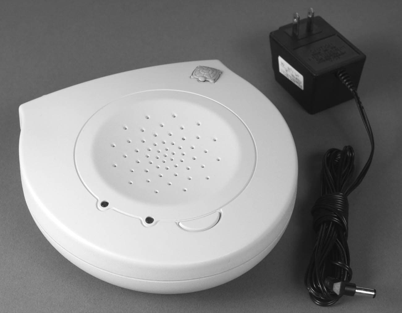
NRA002TER98RX
Oct 28, 1998Pool Monitor Alarm Receiver
Equipment Class
CYY - Communications Receiver used w/Pt 15 Transmitter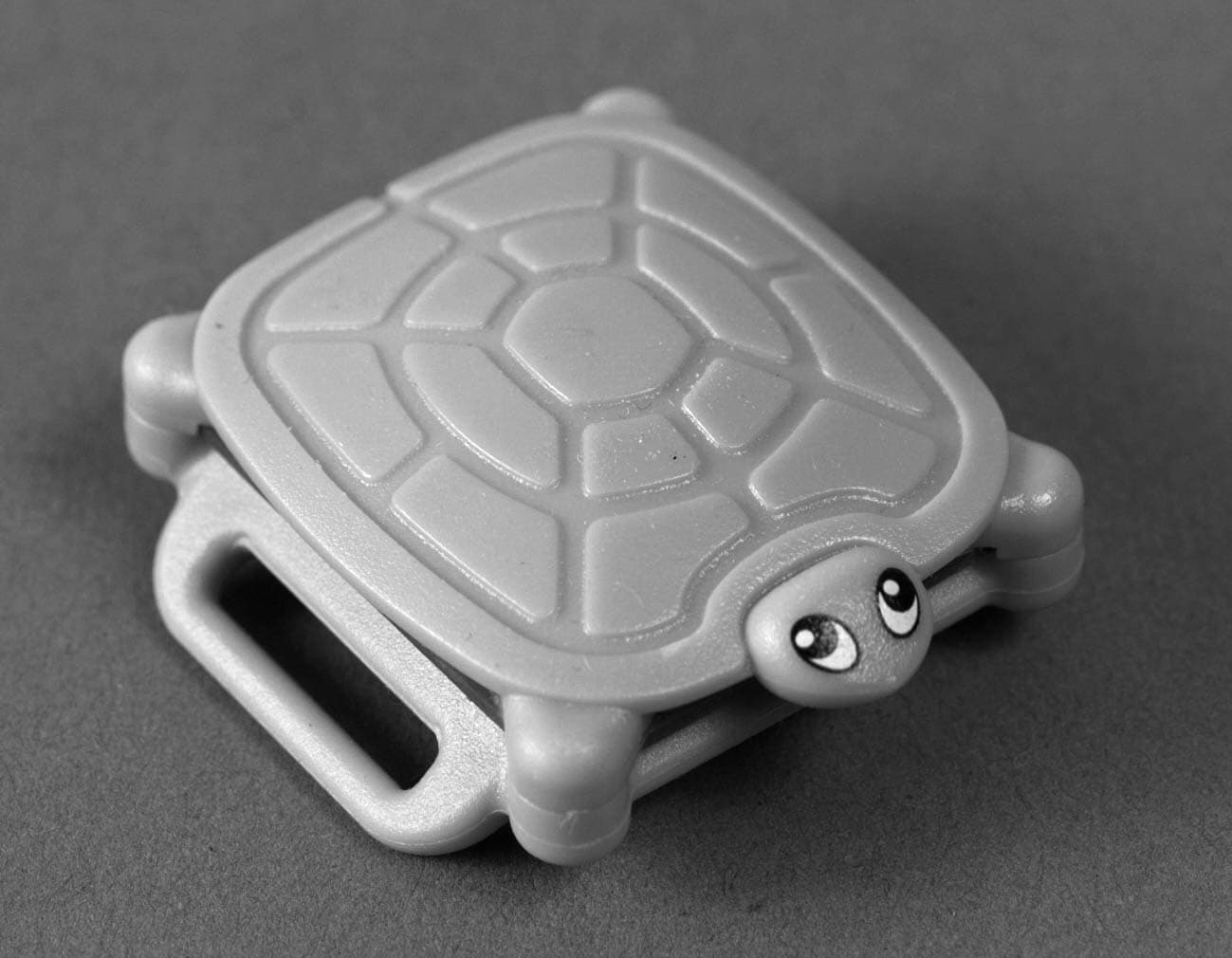
NRA001TER98TX
Oct 18, 1998Alarm Transmitter
Equipment Class
DSC - Part 15 Security/Remote Control Transmitter