NRA-002TER06TXGate Alarm Transmitter
Terrapin Communications Inc.
Click to zoom
Application Details
- Equipment Class
- DSC - Part 15 Security/Remote Control Transmitter
- Date of Grant
- Jul 27, 2006
- Application Purpose
- Original Equipment
- Date of Application
- Jul 27, 2006
- Equipment Note
- Gate Alarm Transmitter
- Frequency Range
- 318.00000000 - 318.00000000
- Company
- Terrapin Communications Inc.
- Country
- Canada
Documents & Files
Document Text
Text extracted from the exhibit documents filed with the FCC. Open a document above to read the original.
Users Manual
7/28/2006 SAFETY TURTLE WIRELESS GATE ALARM MODEL GA-101/GA-ML-101 OPERATING INSTRUCTIONS 1. The Safety Turtle® User Guide that comes with the Base Station explains the functionality of the Safety Turtle system and the Base Station. The following Instructions are supplemental to the Safety Turtle User Guide. 2. The Gate Alarm transmits but does not alarm locally. Alarming occurs only at the Safety Turtle Base Station, which is purchased separately. All Safety Turtle sensors [Turtles, Gate Alarms and Panic Buttons] must be one color to work with one Base Station. The baby Turtle coding plug and sensors all depict this color. 3. Refer to accompanying diagrams of models GA-101 and GA-ML-101 Gate Alarm. Note positions of adult bypass switch and LED. 4. The Gate Alarm is water resistant but not waterproof. Do not immerse or allow water to enter from the bottom. 5. Avoid prolonged depression of adult bypass switch which casues LED to be on. 6. Before the model GA-101 or GA-ML-101 Gate Alarm sensor/transmitter can function, it must be installed on a gate. See separate Gate Alarm INSTALLATION INSTRUCTIONS. The last step in the installation is to insert the battery into its holder. Do this after the Base Station is plugged in, with its green light on, and is not alarming. 7. If the Base Station alarms as soon as the Gate Alarm sensor battery is installed, check to make sure the gate is properly latched. If pressing moon-shaped button on Base Station does not completely silence the alarm, the reed switch and magnet [see INSTALLATION INSTRUCTIONS] are spaced too far apart when the gate is latched, making it appear open to Gate Alarm’s magnetic sensor. Lower or raise the reed switch in the extrusion [model GA-ML-101] or reduce the spacing between the reed switch and magnet [model GA-101]. If this does not work, remove the battery and call the manufacturer for assistance. 8. A Base Station will only alarm when it is in range of the signal transmitted by the installed Gate Alarm. Range varies to maximum of about 250 ft. [75 meters] and must be tested for each installation. To maximize range, locate the Base Station as high as possible and facing the coverage area, e.g. pool and/or alarmed gate(s). See “Locate the Base Station” in Initial Setup and Testing section of the Safety Turtle User Guide. 9. Test operation of the system as follows: • Base Station should be in Test Mode with its amber light on [see Safety Turtle User Guide] • when testing the GA-101 model, gate should be unlatched but opened no further • beeping should start when gate is opened and stop within a few seconds of closing • LED on gate alarm sensor should illuminate for about 11 seconds after adult bypass switch on top of unit is pressed • during this period gate can be opened and closed without causing beeping to occur 7/28/2006 • after testing, Base Station should be returned to Active Mode [see Safety Turtle User Guide] 10. [optional if 9. succesful] Repeat 9. with the Base Station in Active Mode [amber light off]. Once Base Station alarms, press moon-shaped button to turn off. 11. If no alarming occurs when testing the GA-101 model, open the gate wider. If this solves the problem, the spacing between the reed switch and the magnet when the gate is naturally resting on the latch needs to be increased very slightly, so alarming occurs in this situation also. 12. If the Base Station has not so far beeped or alarmed, it needs to be relocated where there is better reception of the signal from the Gate Alarm. See “Locate the Base Station” in Initial Setup and Testing section of the Safety Turtle User Guide. 13. If the system performs correctly in Active Mode but not Test Mode, the CR2032 battery in the Gate Alarm needs replacing [see Safety Turtle User Guide]. Installing the battery: 1. Separate the top and bottom halves of Gate Alarm housing and release battery from holder as shown below. Replace. 2. Reattach the top and bottom halves of Gate Alarm housing. 3. Retest the Gate Alarm. 14. The Safety Turtle gate alarm should be mounted as high as possible on the gate, with the adult bypass switch out of site and out of reach of young children. A visible reminder to use bypass switch is not recommended. Removing the battery 7/28/2006 15. Safety Turtle is not a substitute for diligent supervision or an adequate barrier to restrict the access of children to water hazards. 16. The gate alarm sensor is warranted for one year from date of purchase. Damage or the effects of misuse are not covered by this warranty. See Safety Turtle User Guide for customer support information. 17. Please call Terrapin’s toll-free customer support line at 1-800-368-8121 or email service&terrapin.ca if you need further help. Federal Communications Commission (FCC) Notice This device complies with FCC Part 15 Rules and Industry Canada RSS 210 Issue 2 Regulations. Operation is subject to the following two conditions: ™ this device may not cause harmful interference; and, ™ this device must accept any interference received, including interference that may cause undesired operation. Changes or modifications not expressly approved by Terrapin Communications Inc. could void the user’s authority to operate the equipment.
Users Manual
7/28/2006 SAFETY TURTLE WIRELESS PANIC BUTTON MODEL T101-PB OPERATING INSTRUCTIONS 1. The Safety Turtle® User Guide that comes with the Base Station explains the functionality of the Safety Turtle system and the Base Station. The following Instructions are supplemental to the Safety Turtle User Guide. 2. The Panic Button transmits but does not alarm locally. Alarming occurs only at the Safety Turtle Base Station, which is purchased separately. All Safety Turtle sensors [Turtles, Gate Alarms and Panic Buttons] must be one color to work with one Base Station. The baby Turtle coding plug and sensors all depict this color. 3. Refer to accompanying diagram of Panic Button transmitter. Note position of activation switch. 4. The Panic Button is water resistant but not waterproof. Do not immerse or allow water to enter from the bottom. 5. Do not store or operate Panic Button where inadvertent pressure on activation switch will result in false alarms. 6. A Base Station will not alarm if the Panic Button is outside the Base Station’s coverage area. With an unobstructed line of site, range is about 400 ft. [120 meters], but may be much less indoors. 7. Coverage area of Panic Button must be tested for each Base Station installation. See “Locate the Base Station” in Initial Setup and Testing section of the Safety Turtle User Guide. 8. The activation switch is momentary, not on/off. Transmission is enabled while switch is depressed, and disabled [with some delay] when it is released. 9. Test operation of the system as follows: • Base Station should be in Test Mode with its amber light on [see Safety Turtle User Guide] • Base Station should beep while button on Panic Button [see diagram] is depressed and for a few seconds thereafter • repeat with the Panic Button at other locations in the desired coverage area • after testing, Base Station should be returned to Active Mode [see Safety Turtle User Guide] 10. [optional if 9. succesful] Repeat 9. with the Base Station in Active Mode [amber light off]. Once Base Station alarms, press moon-shaped button to turn off. 11. If the Base Station has not so far beeped or alarmed, it needs to be relocated where there is better reception of the signal from the Panic Button. See “Locate the Base Station” in Initial Setup and Testing section of the Safety Turtle User Guide. Note that more than one Base Station can be used to expand coverage. 7/28/2006 12. If the system functions in Active Mode but not Test Mode, the CR2032 battery in the Panic Button needs replacing [see Safety Turtle User Guide]. Installing the battery: 1. Separate the top and bottom halves of Panic Button and release battery from holder as shown below. Replace. 2. Reattach the top and bottom halves of Panic Button. 3. Retest the Panic Button. 13. The Panic Button is warranted for one year from date of purchase. Damage or the effects of misuse are not covered by this warranty. See Safety Turtle User Guide for customer support information. 7/28/2006 14. Please call Terrapin’s toll-free customer support line at 1-800-368-8121 or email service&terrapin.ca if you need further help. Federal Communications Commission (FCC) Notice This device complies with FCC Part 15 Rules and Industry Canada RSS 210 Issue 2 Regulations. Operation is subject to the following two conditions: ™ this device may not cause harmful interference; and, ™ this device must accept any interference received, including interference that may cause undesired operation. Changes or modifications not expressly approved by Terrapin Communications Inc. could void the user’s authority to operate the equipment.
Operational Description
Operational Description The transmitter emits a coded radio signal when reed switch is closed i.e. Gate is opened. The signal is detected by the receiver, which generates an audio alarm. The transmitter stops emitting a coded signal when reed switch is opened i.e. Gate is closed. The transmitter is power by a replaceable 3V Lithium coin cell battery and employs an integral loop antenna.
Operational Description
Gate Alarm / Panic Button Transmitters The following models use the same PCB with antenna and software, battery power source and housing, but different activation sensors to achieve functional variations, as noted below. All these transmitters, plus the existing Turtle water activated transmitter T101, work with the model B102 receiver. GA Gate Alarm Models GA-101 and GA-ML-101 Both the GA-101 and GA-ML-101 use reed switches to detect a gate opening. Overlay on the housing includes adult bypass switch to inhibit transmission [remote alarm activation] for 11 seconds. The GA-101 model comes with screw/adhesive mountable reed switch and magnet for installation on any wood or chain link gate. This model will be sold as retail product to the home owner. The GA-ML-101 comes with naked reed switch and extrusion for installation on Magna- Latch self-latching gate. The reed switch is positioned adjacent to magnet in moving part of Magna-Latch. This model will be sold OEM to D&D, manufacturer of Magna-Latch, and to pool fence, etc. builders. Panic Button T101-PB In this case, depressing the overlay switch activates the transmitter, so the unit functions as a wireless panic button. The reed switch input is not used.
Test Report
FCC Part 15 Subpart C, 15.231 : February 2005 Test Report: 6W63726 Applicant: Terrapin Communications Inc. 4017 Carling Avenue, Ste 201 Ottawa, Ontario K2K 2A3 Apparatus: Safety Turtle (M/N: GA-101, GA-ML-101, T101-PB) FCC ID: NRA002TER06TX In Accordance With: FCC Part 15 Subpart C, 15.231 Periodic operation in the band 40.66-40.70MHz and above 70 MHz. Tested By: Nemko Canada Inc. 303 River Road Ottawa, Ontario K1V 1H2 Authorized By: Jin Xu, Wireless Specialist Date: May 11, 2006 Total Number of Pages: 17 Nemko Canada Inc. REPORT SUMMARY Report Number: 6W63726 FCC ID: NRA002TER06TX Specification: FCC Part 15 Subpart C, 15.231 Page 2 of 17 Report Summary These tests were conducted on a sample of the equipment for the purpose of demonstrating compliance with Part 15, Subpart C. Radiated tests were conducted in accordance with ANSI C63.4-2003. Radiated emissions are made on an open area test site. A description of the test facility is on file with the FCC. The assessment summary is as follows: Apparatus Assessed: Safety Turtle (M/N: GA-101, GA-ML-101, T101-PB) Specification: FCC Part 15 Subpart C, 15.231 Compliance Status: Complies Exclusions: None Non-compliances: None Report Release History: Original Release Author: Jason Nixon, Telecom Specialist Note that the results contained in this report relate only to the items tested and were obtained in the period between the date of initial receipt of samples and the date of issue of the report. This test report has been completed in accordance with the requirements of ISO/IEC 17025. Nemko Canada Inc. authorizes the applicant to reproduce this report provided it is reproduced in its entirety and for use by the company’s employees only. Any use which a third party makes of this report, or any reliance on or decisions to be made based on it, are the responsibility of such third parties. Nemko Canada Inc. accepts no responsibility for damages, if any, suffered by any third party as a result of decisions made or actions based on this report. Nemko Canada Inc. REPORT SUMMARY Report Number: 6W63726 FCC ID: NRA002TER06TX Specification: FCC Part 15 Subpart C, 15.231 Page 3 of 17 TABLE OF CONTENTS Report Summary......................................................................................................................................... 2 Section 1 : Equipment Under Test............................................................................................................. 4 1.1 Product Identification .................................................................................................................................4 1.2 Samples Submitted for Assessment............................................................................................................4 1.3 Theory of Operation ...................................................................................................................................4 1.4 Technical Specifications of the EUT ..........................................................................................................4 Section 2 : Test Conditions......................................................................................................................... 5 2.1 Specifications .............................................................................................................................................5 2.2 Deviations From Laboratory Test Procedures ............................................................................................5 2.3 Test Environment .......................................................................................................................................5 2.4 Test Equipment...........................................................................................................................................5 Section 3 : Observations ............................................................................................................................. 6 3.1 Modifications Performed During Assessment ............................................................................................6 3.2 Record Of Technical Judgements ...............................................................................................................6 3.3 EUT Parameters Affecting Compliance .....................................................................................................6 3.4 Test Deleted................................................................................................................................................6 3.5 Additional Observations .............................................................................................................................6 Section 4 : Results Summary ..................................................................................................................... 7 4.1 FCC Part 15 Subpart C : Test Results ........................................................................................................8 Appendix A : Test Results .......................................................................................................................... 9 Clause 15.209(a) Radiated Emissions within Restricted Bands ............................................................................9 Clause 15.231(a) Conditions for intentional radiators to comply with periodic operation ..................................11 Clause 15.231(b) Radiated Emissions .................................................................................................................12 Clause 15.231(c) 20dB Bandwidth ......................................................................................................................15 Appendix B : Setup Photographs ............................................................................................................ 16 Appendix C : Block Diagram of Test Setups .....................................................…
Text truncated - open the document above for the full version.
Contact Information
Applicant
Robert G. Lyons(President)
Technical Contact
Terrapin Communications Inc.Robert Lyons
[email protected]613 271 0050
4017 Carling Ave. Suite 201 · Ottawa · Canada
Non-Technical Contact
Terrapin Communications Inc.Robert Lyons
[email protected]613 271 0050
Test Firm
Nemko Canada Inc. (Ottawa)Charles Neal
Technical Specifications
| # | Rule Parts | Frequency Range | Power Output |
|---|---|---|---|
| 1 | 15.231 | 318 MHz - 318 MHz | - |
Other Applications from Terrapin Communications Inc.

NRA-002TER04RX
May 25, 2004Pool Monitor Alarm Receiver
Equipment Class
CYY - Communications Receiver used w/Pt 15 Transmitter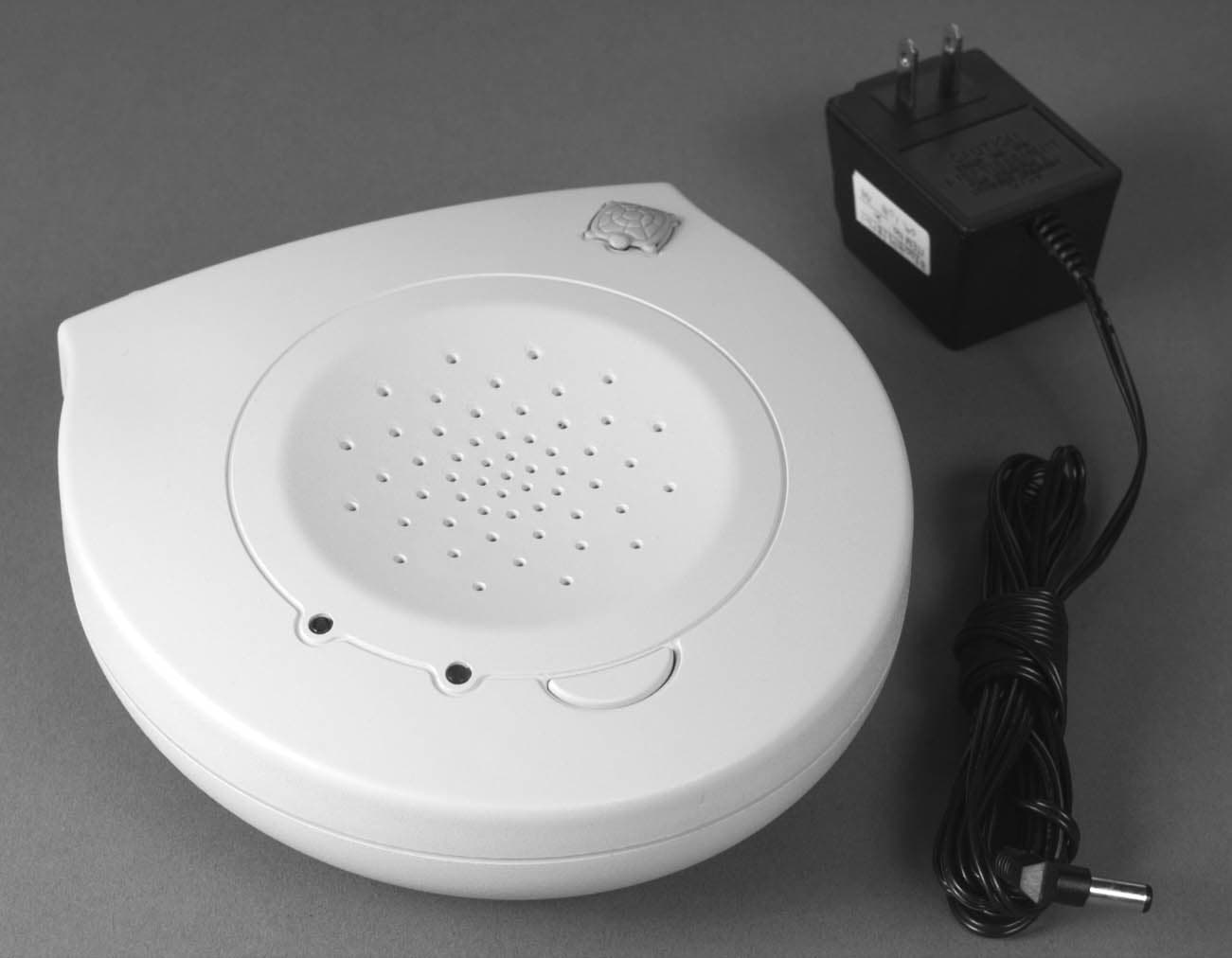
NRA002TER98RX
Oct 28, 1998Pool Monitor Alarm Receiver
Equipment Class
CYY - Communications Receiver used w/Pt 15 Transmitter
NRA001TER98TX
Oct 18, 1998Alarm Transmitter
Equipment Class
DSC - Part 15 Security/Remote Control Transmitter