NS3LELUX615PRWireless Motion Detector Sensor
Lelux Electronics Ltd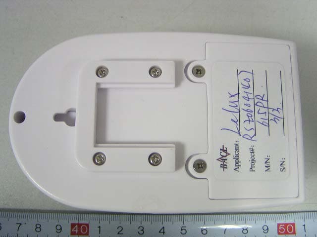
Click to zoom
Application Details
- Equipment Class
- DSC - Part 15 Security/Remote Control Transmitter
- Date of Grant
- May 30, 2006
- Application Purpose
- Original Equipment
- Date of Application
- May 30, 2006
- Equipment Note
- Wireless Motion Detector Sensor
- Frequency Range
- 433.92000000 - 433.92000000
- Company
- Lelux Electronics Ltd
- Country
- Hong Kong
Documents & Files
Document Text
Text extracted from the exhibit documents filed with the FCC. Open a document above to read the original.
Users Manual
OWNER'S MANUAL - 2 - - 1 - 611-615XX-000R INSTALLATION 1. Remove the screw from the battery compartment cover. (fig.1 ) 2. Install an alkaline 9V battery. 3. Replace the battery cover and screw. 4. Mount the wireless motion detector sensor- Choose a suitable location, 5 - 6 feet (1.5 - 2.0 meters) away from floor, then use the swivel wall mount bracket template provided to mark location, drill holes and install anchors and fixture the bracket by screws, Place the main unit into the bracket and slide it down to secure in place (fig 2).you can adjustable bracket obtain the best coverage of the intended protected area.(Fig 3) LEARNING CODE TO MAIN UNIT The motion detector sensor compatible T015, T016, T018 main unit, must learn code to main unit then use, learn code operation see main unit manual. WALK TESTING MOTION DETECTOR SENSOR After select a location, you should test the sensor transmitting range before mount it permanently, turn the CHIME switch to ON of T015, T016 main unit or press HOME button of T018 main unit, then swing at sensor lens by hand, you will hear the main unit sounds “DING DONG” chime if signal is received success- fully, if not, change location is required. You can then test the sensor detection area. Temporarily place the detector at the mounting location and the chime sound will be heard from the main unit. If you walk beyond the sensor detection area, then there will not be a chime sound, by adjust- ing the sensor direction, or the installation location, you can get you desired detection area coverage. BATTERY LOW INDICATOR When 9V battery goes low, the LED will light on 3 seconds and off 1 second, change a new alkaline 9V battery immediately, or the sensor might not detection properly. Warning: Changes or modifications to this unit not expressly approved by the party responsible for compliance will void the user's authority to operate the equipment. Any change to the equipment will void FCC grant. This equipment has been tested and found to comply with the limits for a Class C digital device, pursuant to part 15 of the FCC Rules. These limits are designed to provide reasonable protection against harmful interference in a residential installa- tion. This equipment generates, uses and can radiate radio frequency energy and, if not installed and used in accordance with the instructions, may cause harmful interference to radio communications. However, there is no guarantee that interfer- ence will not occur in a particular installation. If this equipment does cause harmful interference to radio or television reception, which can be determined by turning the equipment off and on, the user is encouraged to try to correct the interference by one or more of the following measures: --Reorient or relocate the receiving antenna. --Increase the separation between the equipment and receiver. --Connect the equipment into an outlet on a circuit different from that to which the receiver is connected. --Consult the dealer or an experienced radio/TV technician for help. This device complies with Part 15 of the FCC Rules. Opera- tion is subject to the following two conditions: (1) this device may not cause harmful interference, and (2) this device must accept any interference received, including interference that may cause undesired operation (fig.1) (fig.2) (fig.3) 1.5~2M1.5~2M WIRELESS MOTION DETECTOR SENSOR
External Photos
External Photos EUT –Front View EUT –Back View
ID Label/Location Info
ID Label Label FCC ID: NS3LELUX615PR
ID Label/Location Info
ID Label/Location Label Location Information Specifications: Text is Black or white in color and is left justified. Labels are printed in indelible ink on permanent adhesive backing or silk-screened onto the EUT or shall be affixed at a conspicuous location on the EUT. Refer to the below arrow.
Internal Photos
Internal Photos EUT- Open View EUT–Uncovered View EUT- PCB Top View EUT–PCB Bottom View
Operational Description
615PR Circuit Description: First, the PIR (Q4) sensor transform infrared signal to electronic signal and send it to the amplify circuit from RC net consisting of R2 R3 C3 C7 C13, the amplify circuit’s core component is U1,OA(operation amplifier-TLC27L4); the signal amplified is sent MCU by RC net (C16 C31 R14). Then, the U3(MCU-EM78P153) will dispose the signal received including the signal of battery low form the voltage comparator consisting of R15-18 C19 U1-D. End, the U3 send code signal to TX module consisting of C1-C4 C12-13 R1-R4 SAW1 Q1 L1-3.The TX module transmit code out by RF(433.92MHz+/-75KHz) in ASK mode. In the same time, MCU drive indication circuit’s LED1 to flash to indicate transmitting.
Operational Description
LELUX ELECTRONICS LTD. PRODUCT SPECIFICATION MODEL: 615PR VERSION: 1.0 ENGINEER: HJS DATE: 28-FEB-06 APPROVAL: ZENG COUNTRY: INT’L ITEM CONDITION SPEC. UNIT 1 WORKING VOLTAGE 6 V 2 STANDBY CURRENT <40 uA 3 WORKING CURRENT (RF Transmitting) <20 mA 4 WORKING DELAY TIME 55+5 SEC. 5 BATTERY LOW DETECT 5.2+0.3 V 6 RF Frequency 433.92+75KHz MHz 7 System RF Modulation ASK 8 Output Power(30cm away) ≥-15 dBm 9 RF Transmit Distance ----T015 (open area 25°C) ≥90 METER 10 PIR Detection Angle (horizontal & vertical) H:110° V:30° Degree 11 PIR Detection Distance (2M height) ≥8 METER 12 BATTERY LIFE (STANDBY) ABOUT 8 MONTHS 13 BATTERY TYPE 6LR61(9V) *1 PCS 14 OPERATING TEMPERATURE 0°C ~ 35°C 15 STORAGE TEMPERATURE -10°C ~ 60°C NOTE:
Schematics
RFmodule_TX01_V10.sch-1 - Wed May 17 08:59:40 2006
Test Report
Note: The test report is specially limited to the above company and this particular sample only. It may not be duplicated without prior written consent of Bay Area Compliance Lab Corp. (ShenZhen). This report must not be used by the client to claim product certification, approval, or endorsement by NVLAP, NIST or any agency of the US Government. FCC PART 15.231 EMI MEASUREMENT AND TEST REPORT For Lelux Electronics Ltd. Unit 6, 10/F, TCL TOWER, NO.8, Tai Chung Road, Tsuen Wan, New Territories, Hong Kong FCC ID: NS3LELUX615PR May 8, 2006 This Report Concerns: Original Report Equipment Type: Wireless Motion Detector Sensor Test Engineer: Simon Mo Report No.: RSZ06041407 Test Date: April 30, 2006 Reviewed By: Chris Zeng Prepared By: Bay Area Compliance Lab Corp. (ShenZhen) 6/F, the 3rd Phase of WanLi Industrial Building, ShiHua Road, FuTian Free Trade Zone, ShenZhen, Guangdong 518038, P.R.China Tel: +86-755-33320018 Fax: +86-755-33320008 Lelux Electronics Ltd. FCC ID: NS3LELUX615PR Report # RSZ06041407 Page 2 of 17 FCC Part 15.231 Test Report TABLE OF CONTENTS GENERAL INFORMATION.......................................................................................................................................3 PRODUCT DESCRIPTION FOR EQUIPMENT UNDER TEST (EUT) .....................................................................................3 OBJECTIVE...................................................................................................................................................................3 RELATED SUBMITTAL(S)/GRANT(S).............................................................................................................................3 TEST METHODOLOGY..................................................................................................................................................3 TEST FACILITY.............................................................................................................................................................3 SYSTEM TEST CONFIGURATION ..........................................................................................................................4 JUSTIFICATION.............................................................................................................................................................4 EUT EXERCISE SOFTWARE..........................................................................................................................................4 SPECIAL ACCESSORIES.................................................................................................................................................4 EQUIPMENT MODIFICATIONS.......................................................................................................................................4 CONFIGURATION OF TEST SETUP.................................................................................................................................5 BLOCK DIAGRAM OF TEST SETUP................................................................................................................................5 SUMMARY OF TEST RESULTS...............................................................................................................................6 §15.203 - ANTENNA REQUIREMENT......................................................................................................................7 STANDARD APPLICABLE..............................................................................................................................................7 §15.205, §15.209, §15.231 (B) - RADIATED EMISSION...........................................................................................8 MEASUREMENT UNCERTAINTY....................................................................................................................................8 EUT SETUP..................................................................................................................................................................8 EMI TEST RECEIVER SETUP.........................................................................................................................................8 TEST EQUIPMENT LIST AND DETAILS...........................................................................................................................9 TEST PROCEDURE........................................................................................................................................................9 STANDARD APPLICABLE..............................................................................................................................................9 CORRECTED AMPLITUDE & MARGIN CALCULATION...................................................................................................9 TEST RESULTS SUMMARY..........................................................................................................................................10 TEST DATA................................................................................................................................................................10 PLOT(S) OF TEST DATA..............................................................................................................................................11 §15.231(C) 20dB BANDWIDTH TESTING..............................................................................................................14 REQUIREMENT...........................................................................................................................................................14 TEST EQUIPMENT LIST AND DETAILS.........................................................................................................................14 TEST PROCEDURE.......................................................................................................................................…
Text truncated - open the document above for the full version.
Test Setup Photos
Test Setup Photos Radiated Emission – Front View (30-1000MHz) Radiated Emission - Rear View (30-1000MHz) Radiated Emission – Front View (Above 1000MHz) Radiated Emission – Rear View (Above 1000MHz)
Contact Information
Applicant
Luke Lo(President)
Test Firm
Bay Area Compliance Laboratory Corp. (Shenzhen)John Chan
Technical Specifications
| # | Rule Parts | Frequency Range | Power Output |
|---|---|---|---|
| 1 | 15.231 | 433.92 MHz - 433.92 MHz | - |
Other Applications from Lelux Electronics Ltd
NS3-108WR
May 16, 2015Wireless Door/window Sensor
Equipment Class
DSC - Part 15 Security/Remote Control TransmitterNS3-615NP
May 14, 2015Wireless Motion Detector Sensor
Equipment Class
DSC - Part 15 Security/Remote Control Transmitter
NS3639S
Feb 04, 2015VISITOR CHIME AND WATCH DOG/ALARM
Equipment Class
DXT - Part 15 Low Power Transceiver, Rx Verified
NS3-T058VS
Dec 16, 2014Wireless Security Alarm / Auto Dialer System
Equipment Class
DSR - Part 15 Remote Control/Security Device Transceiver
NS3S615
Nov 24, 2014Wireless Security Alert System
Equipment Class
DSC - Part 15 Security/Remote Control Transmitter