NS901P5MHX-920 SST Module
Microhard Systems Inc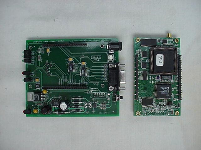
Click to zoom
Application Details
- Equipment Class
- DSS - Part 15 Spread Spectrum Transmitter
- Date of Grant
- Mar 20, 2001
- Application Purpose
- Original Equipment
- Date of Application
- Jan 26, 2001
- Equipment Note
- MHX-920 SST Module
- Frequency Range
- 902.47000000 - 927.61000000
- Company
- Microhard Systems Inc
- Country
- Canada
Documents & Files
Document Text
Text extracted from the exhibit documents filed with the FCC. Open a document above to read the original.
Users Manual
Operating Manual MHX-920 900 MHz Spread Spectrum OEM Transceiver Revision 1.20, December 21, 2000 Microhard Systems Inc. #110, 1144 - 29 th Ave. N.E. Calgary, Alberta T2E 7P1 Phone: (403) 248-0028 Fax: (403) 248-2762 www.microhardcorp.com iiMHX-920 Operating Manual MHX-920 900 MHz Spread-Spectrum Embedded Modem WARNING In order to comply with the FCC/IC adopted RF exposure requirements, this transmitter system will be installed by the manufacturer's reseller professional. Installation of all antennas must be performed in a manner that will provide at least 23 cm clearance from the front radiating aperture, to any user or member of the public. EQUIPMENT LABELING The manufacturer, product name, and FCC and Industry Canada identifiers of this product must appear on the outside label of the end-user equipment. l This manual contains information of proprietary interest to Microhard Systems Inc. It has been supplied in confidence to purchasers and users of the MHX-920, and by accepting this material the recipient agrees that the contents will not be copied or reproduced, in whole or in part, without prior written consent of Microhard Systems Inc. Microhard Systems Inc. has made every effort to assure that this document is accurate and complete. However, the company reserves the right to make changes or enhancements to the manual and/or the product described herein at any time and without notice. Furthermore, Microhard Systems Inc. assumes no liability resulting from any omissions in this document, or out of the application or use of the device described herein. Microhard Systems’ products are appropriate for home, office, or industrial use, but are not authorized for utilization in applications where failure could result in damage to property or human injury or loss of life. The electronic equipment described in this manual generates, uses, and radiates radio frequency energy. Operation of this equipment in a residential area may cause radio interference, in which case the user, at his own expense, will be required to take whatever measures necessary to correct the interference. FCC Declaration of Conformity This device complies with Part 15 of the FCC Rules. Operation is subject to the following two conditions: (1) this device may not cause harmful interference, and (2) this device must accept any interference received including interference that may caused undesired operation. Microhard Systems Inc.’s products are warranted against all failures which occur as a result of defective material or workmanship within 12 months of purchase by the user. This warranty does not extend to products that, in the opinion of Microhard Systems Inc., have been subject to misuse, accidents, lightning strikes, improper installation or application, nor shall it extend to units which have, in Microhard Systems Inc.’s opinion, been opened, tampered with or repaired by an unauthorized facility. Microhard Systems Inc. Leaders in Wireless Telecom #110, 1144 - 29 th Ave. N.E. Calgary, Alberta T2E 7P1 Phone: (403) 248-0028 Fax: (403) 248-2762 www.microhardcorp.com © 2000 by Microhard Systems Inc., All Rights Reserved. HyperTerminal is copyrighted by Hilgraeve Inc, and developed for Microsoft. Microsoft and Windows are registered trademarks of Microsoft Corporation. pcANYWHERE and Symantec are registered trademarks of Symantec Corp. All other products mentioned in this document are trademarks or registered trademarks of their respective holders. Manual Revision 1.20, December 21, 2000. iiiMHX-920 Operating Manual Contents 1.Introduction 1.0Product Overview.............................................................................................................................................................................. 1 1.1Features.............................................................................................................................................................................................. 1 1.2About this Manual............................................................................................................................................................................. 2 2.Electrical/Physical 2.0Functional Block Diagram................................................................................................................................................................. 3 2.1Pinout................................................................................................................................................................................................. 4 2.2LED Operation................................................................................................................................................................................... 6 2.3DC Characteristics............................................................................................................................................................................. 8 2.4AC Characteristics..............................................................................................................................................................................9 3.Modes of Operation.....................................................................................................................................................................................11 3.1Data Mode........................................................................................................................................................................................11 3.2Command Mode...............................................................................................................................................................................12 3.2.1AT Command Interface.......................................................................................................................................................13 3.3Switching Between Command and Data Modes.....…
Text truncated - open the document above for the full version.
Cover Letter(s)
#110, 1144 - 29th Avenue N.E. Calgary, Alberta T2E 7P1 Tel: (403) 248-0028 Fax: (403) 248-2762 Website: http://www.microhardcorp.com FCC ID: NS901P5 January 22, 2001 Federal Communications Commission OET Laboratory Division. 7435 Oakland Mills Rd. Columbia, MD 21046 Re: Request for Confidentiality. We request that the enclosed design documents of our MHX-920 product (FCC ID NS901P5), specifically our schematics and bill of materials, be held confidential. Extensive research and development efforts have provided us with spread spectrum radio technology that significantly outperforms much of the competition. This new technology gives our company a competitive advantage. Our efforts could be quickly undermined if the design information were to be made public. Thank you in advance. Hany H. Shenouda President
External Photos
MHX-920 Transceiver External Photographs MHX-920 Transceiver External Photographs MHX-920 Transceiver External Photographs MHX-920 Transceiver External Photographs MHX-920 Transceiver External Photographs MHX-920 Transceiver External Photographs
ID Label/Location Info
FCC ID LABEL FORMAT AND LOCATION TOP VIEW FCCID: NS901P5 This device complies with Part 15 of the FCC Rules. Operation of this device is subject to the following conditions: (1) This device may not cause harmful interference, and (2) this device must accept any interference received, including interference which may cause undesired operation. MHX-920
Internal Photos
MHX-920 Transceiver External Photographs MHX-920 Transceiver External Photographs MHX-920 Transceiver External Photographs MHX-920 Transceiver External Photographs MHX-920 Transceiver External Photographs MHX-920 Transceiver External Photographs
Operational Description
Microhard Systems Inc. MHX-920 Operational Description MHX-920 Operational Description1 1.0 Operational Description The MHX-920 is a high-performance embedded spread spectrum data transceiver. Users communicate with this module via an asynchronous RS-232 interface. All data that users send to the module is buffered in banks of SRAM memory, packetized with the appropriate header information, and sent over the air at a fixed bit rate. The microprocessor inside the module precisely controls the bit-width, packet size, and hopping algorithm, to ensure that the RF occupied bandwidth and channel dwell-times remain constant. Users have no ability to modify the occupied bandwidth of the transmitted data. Users power the module from a 5 - 5.5V source. This is linearly regulated down to 4.5V for the radio circuitry. This ensures that any changes in input voltage will not have any effect on the radiated power, which is limited to 1W. The MHX-920 modem can be configured for a wide range of applications. The module is designed such that all communication is through one serial port (Pins 21 to 28 on the module). This port has two functions: 1. It provides the asynchronous interface with the host equipment for data that is sent/received on the RF channel. When operating in this fashion, the module is said to be in data mode. 2. It is also used for configuring and programming the module. When operating in this fashion, the module is said to be in command mode. The functionality of any particular MHX-920 can be configured as follows: nMaster Point-to-Point: The modem is configured to communicate with a single Slave, either directly, or through one or more Repeaters. nMaster Point-to-Multipoint: The modem is configured to communicate with one or more Slaves and/or Repeaters. nSlave: The modem is configured to communicate with one Master either directly or through one or more Repeaters.. nRepeater: The modem is configured to pass information from either a Master or another Repeater onto subsequent Repeaters and/or Slaves and vice versa. The Repeater also acts as a Slave in the sense that, like a Slave, it passes information to/from its serial port. The MHX-920 is a frequency hopping transceiver, meaning that it “hops” to a new frequency after a predetermined time interval. This time interval is a fixed time set by the user, and can range from 8ms to 120ms. The MHX-920 hops according to a pseudorandom pattern of 50 different channels. There are 64 available channels with spacing of 400 kHz starting at 902.4 MHz and going up to 927.6 MHz. The RF connector on the module is an MCX straight PC mount jack. The manufacturer's part no. is: Johnson # 133-3701-211 Microhard Systems Inc. MHX-920 Operational Description MHX-920 Operational Description2 1.1 Functional Block Diagram Figure 1 is a functional block diagram of the MHX-920 module Antenna Switch Mixer LNAMixer IF Demod Frequency Synthesizer PA Comparator + - uC 8 bit data bus UART (DCE) GAIN A/D SRAM EEPROM SRAM CTS DCD DSR RxD DTR TxD RTS \Config \Reset RSSI1-3 RXMODE TXMODE DVcc AVcc GND Linear Regulator Figure 1 - Functional Block Diagram
Operational Description
Dwell Time The MHX-920 is a frequency hopping transceiver, meaning that it “hops” to a new frequency after a predetermined time interval. The receiver shall hop in synchronization with the master when the network address and the hopping patterns of the master and the slave are set to the same. The hopping patterns are stored in an onboard EEPROM and programmed in the factory. The hop time interval is a fixed time set by the user, and can range from 8ms to 120ms. The master’s transmit time is less than the 120ms and varies depending on the size of the packet. See plots 1 and 2. In plot 1, there is data on the serial port and the unit transmits for 51.99ms. In any case the maximum time for the system to be on a single channel is 120ms as stated in the MHX-920 User’s Manual. In plot 2, there is no data transmitted over the RS-232 port and hence the master only transmits a beacon, which is 3.85ms in duration. Plot 2. Master Transmit Time on a Given Channel in the Pseudorandom Hop Sequence with no Data on RS-232 port Plot 1. Master Transmit Time on a Given Channel in the Pseudorandom Hop Sequence with Data on RS-232 port
RF Exposure Info
RF Exposure Calculations: The following information provides the minimum separation distance for each of the antennas provided with the MHX-920 module, as calculated from FCC OET 65 Appendix B, Table 1B Guidelines for General Population/Uncontrolled Exposure. This calculation is based on the highest EIRP possible from the system, considering maximum power and antenna gain. The formula used was: S = (Po*G)/(4*pi*r^2) Where S = 0.62 mW/cm^2 for 928 MHz Where Po = 100 mW for Yagi antennas (max. power set at factory) Where Po = 1.0 Watt for Omni antennas (max. power user configurable) For:12 dB Yagi Antennar = 14 cm 2.5dB Omni Antennar = 15 cm 6 dB Omni Antennar = 23 cm The following statement will be presented in the MHX-920 User Manual: WARNING In order to comply with the FCC/IC adopted RF exposure requirements, this transmitter system will be installed by the manufacturer's reseller professional. Installation of all antennas must be performed in a manner that will provide at least 23 cm clearance from the front radiating aperture, to any user or member of the public
RF Exposure Info
RF Exposure Calculations: The following information provides the minimum separation distance for each of the antennas provided with the MHX-920 module, as calculated from FCC OET 65 Appendix B, Table 1B Guidelines for General Population/Uncontrolled Exposure. This calculation is based on the highest EIRP possible from the system, considering maximum power and antenna gain. The formula used was: S = (Po*G)/(4*pi*r^2) Where S = 0.6 mW/cm^2 for 902.47 MHz Where Po = 100 mW for Yagi antennas (max. power set at factory) Where Po = 1.0 Watt for Omni antennas (max. power user configurable) For:12 dB Yagi Antennar = 14 cm 2.5dB Omni Antennar = 15 cm 6 dB Omni Antennar = 23 cm The following statement will be presented in the MHX-920 User Manual: WARNING In order to comply with the FCC/IC adopted RF exposure requirements, this transmitter system will be installed by the manufacturer's reseller professional. Installation of all antennas must be performed in a manner that will provide at least 23 cm clearance from the front radiating aperture, to any user or member of the public
Test Report
N N N a a a t t t i i i o o o n n n a a a l l l C C C e e e r r r t t t i i i f f f i i i c c c a a a t t t i i i o o o n n n L L L a a a b b b o o o r r r a a a t t t o o o r r r y y y 8370 Court Avenue, Suite B-1 Ellicott City, Maryland 21043 (410) 461-5548 FOR Microhard Systems, Inc. #110, 1144 – 29 th Ave., N.E. Calgary Alberta, Canada T2E 7P1 FCC ID:NS901P5 January 22, 2001 FCC REPORT OF RADIO INTERFERENCE FCC ID #: NS901P5 1 TABLE OF CONTENTS 1.0Introduction 1.1Summary 2.0Description of Equipment Under Test (EUT) 2.1EMI Countermeasure 3.0Test Program 4.0 Test Configuration 5.0Conducted Emissions Scheme 6.0Radiated Emissions Scheme TABLES Table 1.Support Equipment Table 2.Interface Cables Table 3.Measurement Equipment EXHIBITS Exhibit 1.EUT Photographs Exhibit 2.Schematic Diagram Exhibit 3.User Manual NCL PROJ.# Microhard-573 FCC ID #: NS901P5 2 1.0 Introduction: This report has been prepared on behalf of Microhard Systems, Inc., to support the attached Application for a Certification of a Part 15 Spread Spectrum Transmitter module. The Equipment Under Test (EUT) was the Model: MHX-920 Wireless Modem Transceiver OEM Module. Radio-Noise Emissions tests were performed according to FCC Public Notice 54797, titled “Guidance on Measurement for Direct Sequence SST”. The measuring equipment conforms to ANSI C63.2 Specifications for Electromagnetic Noise and Field Strength Instrumentation. Testing was performed at National Certification Laboratory in Ellicott City, MD. Site description and site attenuation data have been placed on file with the FCC’s sampling and Measurements Branch. FCC acceptance was granted on May 26, 1993. 1.1 Summary: The Microhard Systems, Inc., Model: MHX-920 Wireless Modem Transceiver OEM Module complies with the FCC limits (15.247) for a Frequency Hopping SST. FCC ID #: NS901P5 3 2.0 Description of Equipment Under Test (EUT): The EUT features: 3.0 Test Program: This report contains measurement charts and data as evidence for the following tests performed: 1.(15.247b) Peak RF output power. 2. (15.247c) Field Strength of harmonics and spurious out-of-band emissions. 3. (15.247c) RF Antenna Conducted of harmonics and spurious out-of-band emissions. 4. (15.247a) 20 dB Emission Bandwidth. 5. (15.207) Power Line Conducted Emissions. 6.(15.247c) Band Edge emissions. MCX Antenna Connector per 15.203 +30 dBm RF Output Max. 902-928 MHz Frequency Range 350 kHz 20 dB Emission Bandwidth 64 Hopping Channels 400 kHz Channel Separation 172.8 kbps Data Rate (Radio Link) 115.2 kbps Max Data Rate (DCE) FCC ID #: NS901P5 4 4.0 Test Configuration: RF antenna output tests such as Bandwidth, Spurious/Harmonics, Power output, were taken with the transmitter antenna connector feeding directly into the spectrum analyzer via external 20 db attenuator. The analyzer’s internal attenuator was adjusted to prevent overloading of the front end. The transmitter is modulated at 115.2 kbps which is the highest available data rate. Field strength measurements were taken with the transmitter feeding a yagi, or omni antenna aimed at the receiving antenna. Testing was performed using the highest gain antenna from each design family (yagi, omni) with the power setting at 1 Watt for the omni antenna, and 100 mW for the higher gain yagi. A list of all antennas that will be sold with the MHX-920 Wireless Module follows: 12 dBi Yagi Antenna 11 dBi Yagi Antenna 2.5 dBi Omni Antenna - 900 MHz Rubber Ducky 6 dBi Omni Antenna FCC ID #: NS901P5 5 PEAK POWER TEST RESULTS Limit:1 watt (30 dBm) Condition:Transmitter is set to a single FM modulated channel Reading from spectrum analyzer with 1 MHz Resolution Bandwidth setting: Low Channel:902.47Hz-(+29.6 dBm) Mid Channel:914.83 MHz -(+29.8 dBm) High Channel:927.61 MHz-(+29.8 dBm) SEE FOLLOWING THREE (3) PLOTS OF MODULATED CARRIER FCC ID #: NS901P5 6 PEAK RF POWER – MODULATED CARRIER (1 MHz RES. BW) Low Channel FCC ID #: NS901P5 7 PEAK RF POWER – MODULATED CARRIER (1 MHz RES. BW) Mid Channel FCC ID #: NS901P5 8 PEAK RF POWER – MODULATED CARRIER (1 MHz RES. BW) High Channel FCC ID #: NS901P5 9 20 dB EMISSION BANDWIDTH Maximum 20 dB BW:0.500 MHz RBW Setting on S.A.:3kHz Condition:Transmitter is set to a single channel FM modulated at 115.2 kbps Reading from Spectrum Analyzer: Channel 1:902.47 MHz-342 kHz Channel 32:914.83 MHz-349 kHz Channel 64:927.61 MHz-350 kHz SEE FOLLOWING THREE (3) PLOTS OF MODULATED CARRIER FCC ID #: NS901P5 10 20 dB EMISSION BANDWIDTH – MODULATED CARRIER (3 kHz RES. BW) Low Channel FCC ID #: NS901P5 11 20 dB EMISSION BANDWIDTH – MODULATED CARRIER (3 kHz RES. BW) Mid Channel FCC ID #: NS901P5 12 20 dB EMISSION BANDWIDTH – MODULATED CARRIER (3 kHz RES. BW) High Channel FCC ID #: NS901P5 13 RF ANTENNA CONDUCTED SPURIOUS/HARMONICS EMISSIONS Limit:20 dB below Carrier Level Measured with 100 kHz RBW RBW Setting on S.A.: 100 kHz Condition:Transmitter is set to a single FM modulated channel. RF Power = 30 dBm Three separate measurements are performed to show harmonic and spurious emissions generated with the transmitter tuned to low, middle, and high parts of the spectral range. SEE FOLLOWING THREE (3) PLOTS & DATA TABLES FCC ID #: NS901P5 14 FCC Part 15.247(c) – Conducted Spurious Emissions Frequency of Carrier = 902.47 MHz Limit = 20 dBc Condition:Transmitter is set to a single FM modulated channel. TEST RESULTS LIMIT:-20 dB FROM PEAK CARRIER ComponentFrequency (MHz)Result (dB From Peak) Harmonic1805.60-51.0 Harmonic2708.40-67.0 Harmonic3611.20-69.0 Harmonic4514.00-73.0 Harmonic5416.80-74.0 Harmonic6319.60-75.0 Harmonic7222.40-75.0 Harmonic8125.20-75.0 Harmonic9028.00-75.0 FCC ID #: NS901P5 15 FCC Part 15.247(c) – Conducted Spurious Emissions Frequency of Carrier = 914.8 MHz Limit = 20 dBc Condition:Transmitter is set to a single FM modulated channel. TEST RESULTS LIMIT:-20 dB FROM PEAK CARRIER ComponentFrequency (MHz)Result (dB From Peak) Harmonic1829.40-50.6 Harmonic2744.10-65.0 Harmonic3658.80-73.0 Harmonic4573.50-73.0 Harmonic5488.20-74.0 Harmonic64…
Text truncated - open the document above for the full version.
Test Setup Photos
MHX-920 Transceiver Conducted Emission Photographs MHX-920 Transceiver Conducted Emissions Photographs
Contact Information
Applicant
Hany Shenouda(President)
Technical Contact
National Certification LabBrian Haghtalab
[email protected]410 461 5548
8370 Court Ave. · Ellicott City, Maryland · United States
Non-Technical Contact
National Certification LabBrian Haghtalab
[email protected]410 461 5548
Test Firm
National Certification LaboratoryBrian Haghtalab
Technical Specifications
| # | Rule Parts | Frequency Range | Power Output |
|---|---|---|---|
| 1 | 15C | 902.47 MHz - 927.61 MHz | 950.00 mW |
Other Applications from Microhard Systems Inc
NS920N920T
May 28, 2020n920T 2020 900MHz OEM Frequency Hopping/DTS Module
Equipment Class
DSS - Part 15 Spread Spectrum Transmitter
NS915PX2
Jul 01, 2015Pico 2.4GHz High Speed 1W Module
Equipment Class
DTS - Digital Transmission System
NS914P400
Sep 25, 2014Pico 900MHz 1W FHSS/400MHz 2W License Band Module
Equipment Class
DSS - Part 15 Spread Spectrum Transmitter
NS913P900
Sep 09, 2013Pico 900 MHz 1W FHSS Module
Equipment Class
DSS - Part 15 Spread Spectrum Transmitter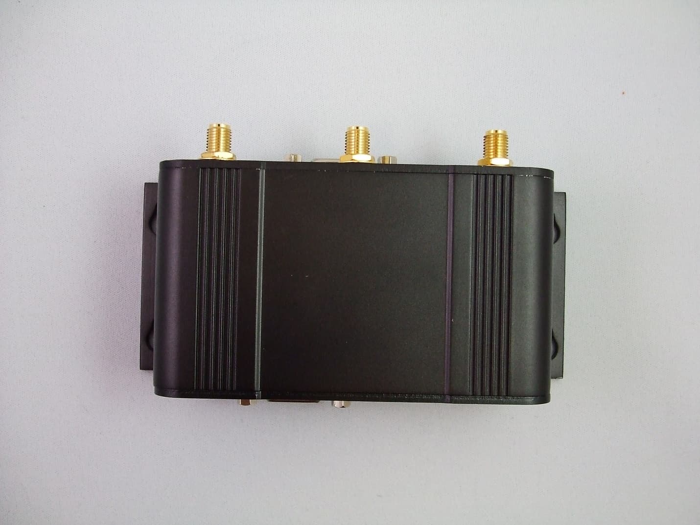
NS9IPN4GNBG30
Apr 22, 2013IPn4G 4G LTE Cellular Ethernet Bridge/Serial Gateway
Equipment Class
JBP - Part 15 Class B Computing Device Peripheral