NS998P001X01Wireless Modem
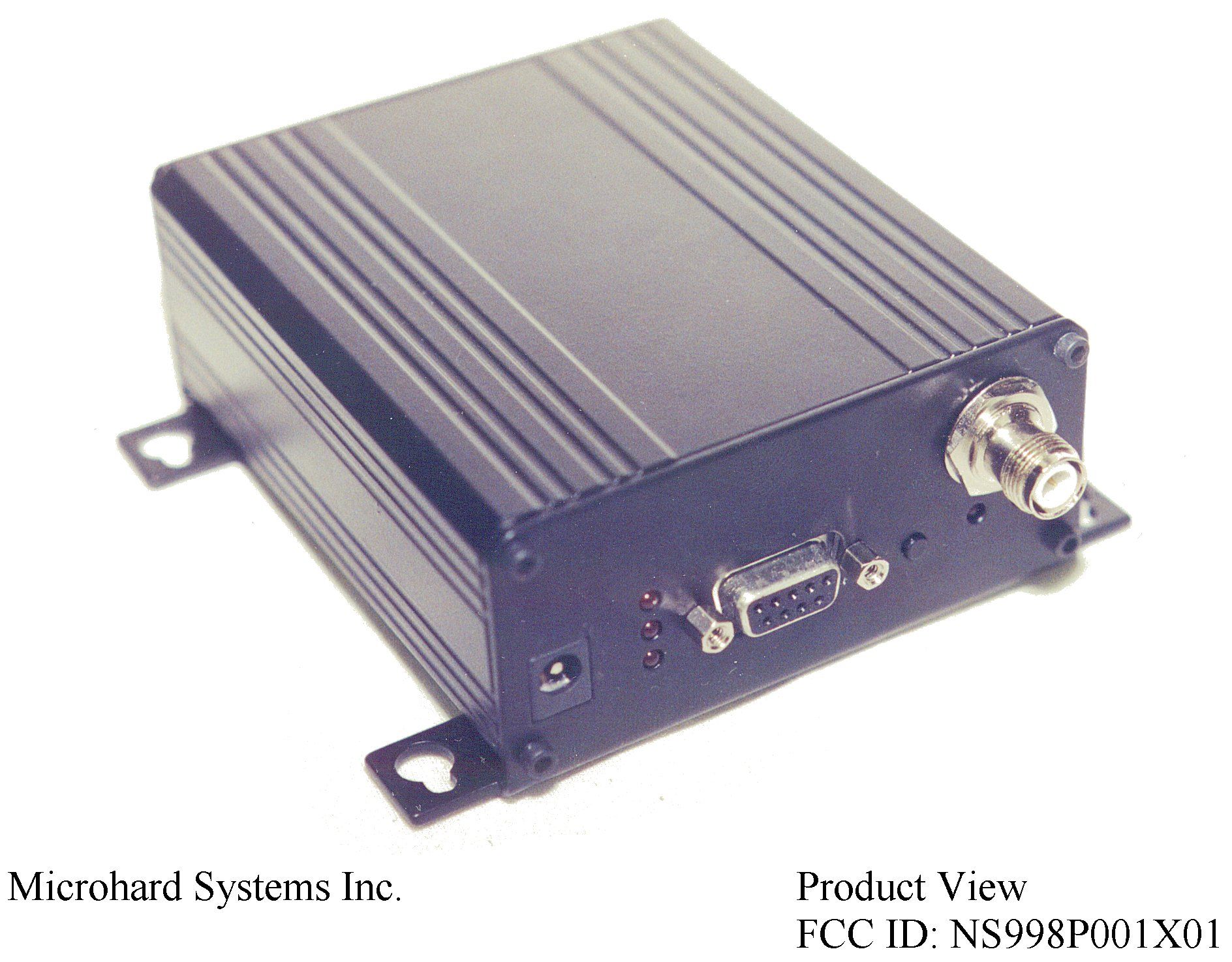
Microhard Systems Inc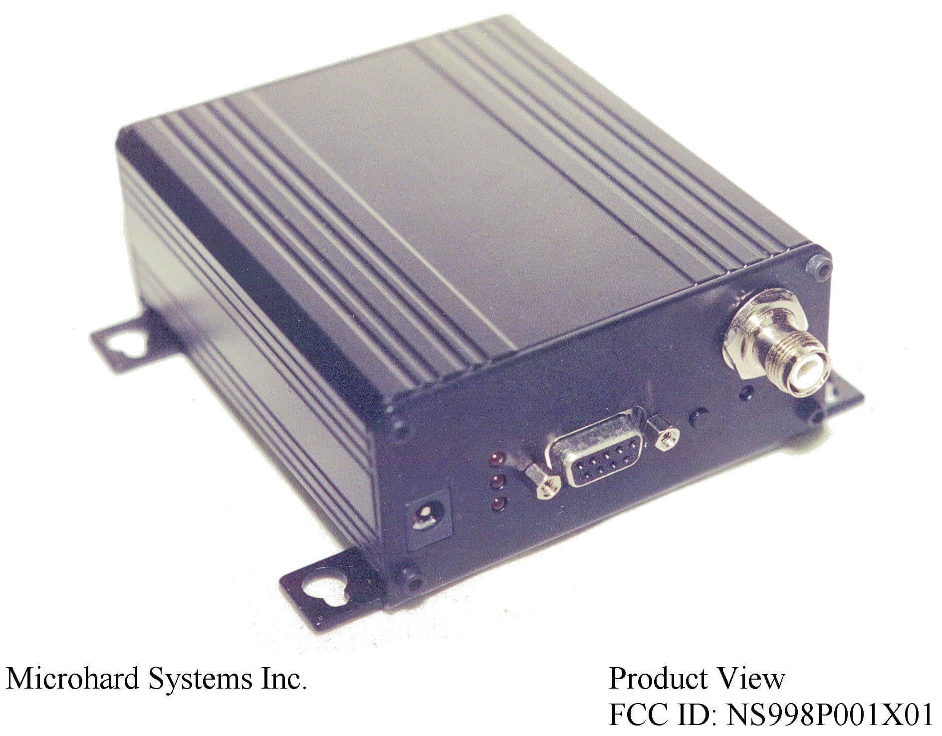
Click to zoom
Application Details
- Equipment Class
- DSS - Part 15 Spread Spectrum Transmitter
- Date of Grant
- Sep 27, 1998
- Application Purpose
- Original Equipment
- Date of Application
- Aug 04, 1998
- Equipment Note
- Wireless Modem
- Frequency Range
- 902.50000000 - 927.80000000
- Company
- Microhard Systems Inc
- Country
- Canada
Documents & Files
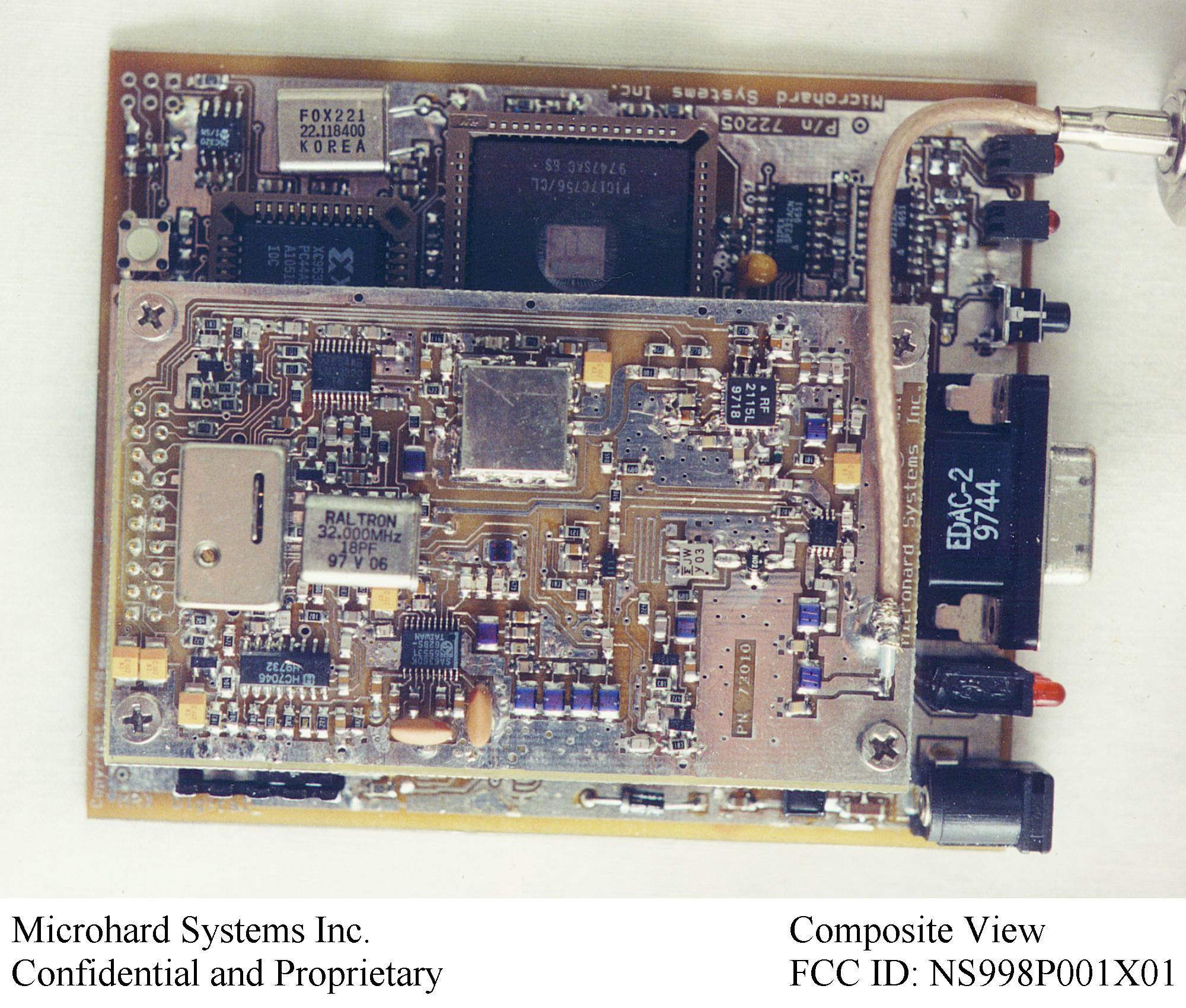
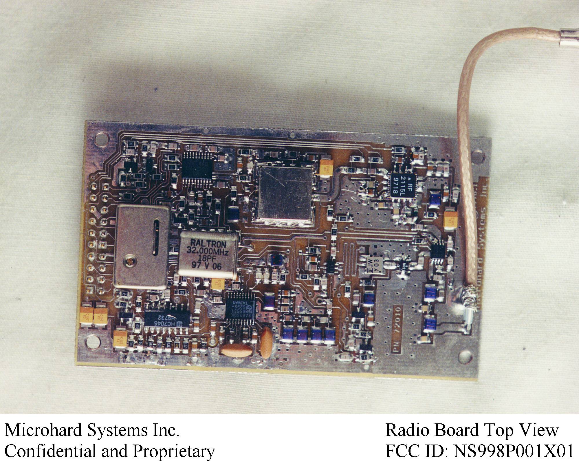
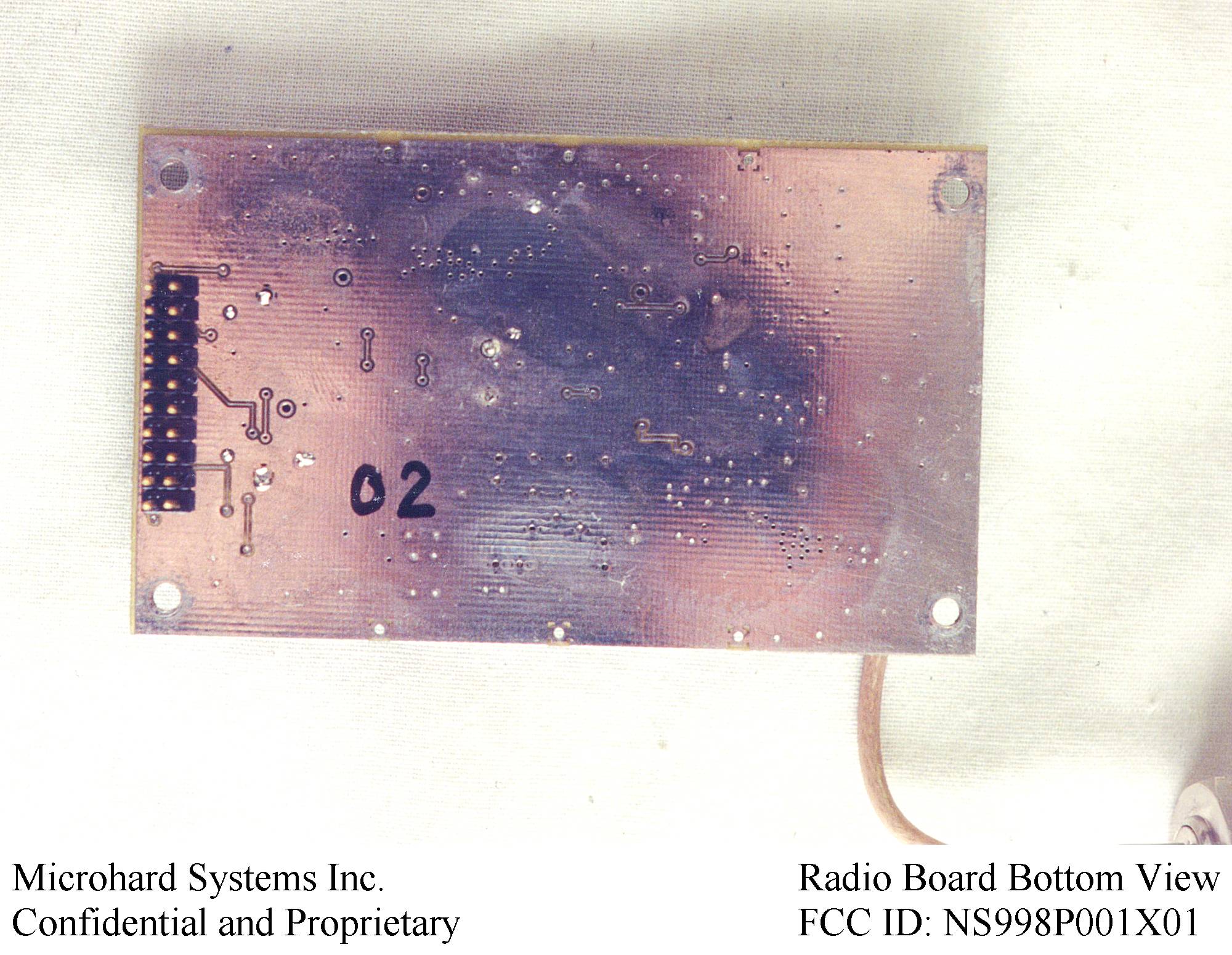
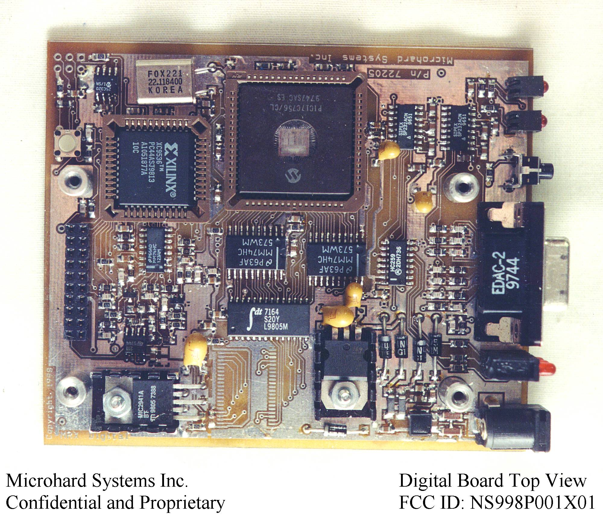
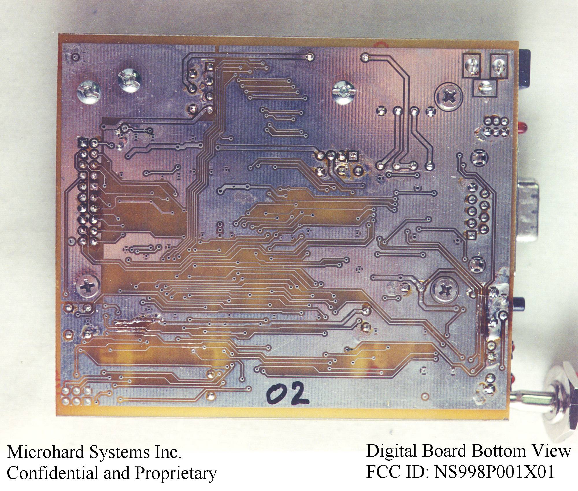
Document Text
Text extracted from the exhibit documents filed with the FCC. Open a document above to read the original.
Users Manual
MRX-900 Operating Manual: Contentsi MRX-900 900 MHz Spread-Spectrum Wireless Modem Operating Manual Microhard Systems Inc. Leaders in Wireless Telecom iiMRX-900 Operating Manual MRX-900 900 MHz Spread-Spectrum Wireless Modem This manual contains information of proprietary interest to Microhard Systems Inc. It has been supplied in confidence to purchasers and users of the MRX-900, and by accepting this material the recipient agrees that the contents will not be copied or reproduced, in whole or in part, without prior written consent of Microhard Systems Inc. Microhard Systems Inc. has made every effort to assure that this document is accurate and complete. However, the company reserves the right to make changes or enhancements to the manual and/or the product described herein at any time and without notice. Furthermore, Microhard Systems Inc. assumes no liability resulting from any omissions in this document, or out of the application or use of the device described herein. Microhard Systems’ products are appropriate for home, office, or industrial use, but are not authorized for utilization in applications where failure could result in damage to property or human injury or loss of life. The electronic equipment described in this manual generates, uses, and radiates radio frequency energy. Operation of this equipment in a residential area may cause radio interference, in which case the user, at his own expense, will be required to take whatever measures necessary to correct the interference. FCC Declaration of Conformity This device complies with Part 15 of the FCC Rules. Operation is subject to the following two conditions: (1) this device may not cause harmful interference, and (2) this device must accept any interference received including interference that may caused undesired operation. M icrohardI S nc.ystems Leaders in Wireless Telecom #209 - 12 Manning Close N.E. Calgary, Alberta T2E 7N6 Phone: (403) 248-0028 Fax: (403) 248-2762 www.microhardcorp.com © 1998 by Microhard Systems Inc., All Rights Reserved. MRX-900 is a registered trademark of Microhard Systems Inc. HyperTerminal is copyrighted by Hilgraeve Inc, and developed for Microsoft. Microsoft and Windows are registered trademarks of Microsoft Corporation. pcANYWHERE and Symantec are registered trademarks of Symantec Corp. All other products mentioned in this document are trademarks or registered trademarks of their respective holders. Manual Revision 1.0, June 20, 1998. MRX-900 Operating Manual: Contentsiii Contents 1.Introduction 1.0Product Overview....................................................................................................................................... 1 1.1Features....................................................................................................................................................... 1 1.2About this Manual....................................................................................................................................... 2 2.Initial Installation and Setup 2.0Unpacking and Inspection........................................................................................................................... 3 2.1Additional Requirements............................................................................................................................ 3 2.2Connectors and Indicators........................................................................................................................... 4 2.3Hardware Setup........................................................................................................................................... 4 2.4Configuration.............................................................................................................................................. 5 2.4.1Quick Start Approach....................................................................................................................... 5 A. Point-to-Point............................................................................................................................. 5 B. Point-to-Multipoint..................................................................................................................... 6 3.Configuration Options 3.0Changing Parameters in Configuration Menu............................................................................................. 7 3.1Operating Mode.......................................................................................................................................... 7 3.2Serial Baud Rate......................................................................................................................................... 9 3.3Wireless Link Rate...................................................................................................................................... 9 3.4Network Address....................................................................................................................................... 10 3.5Unit Address............................................................................................................................................. 10 3.6Hopping Pattern........................................................................................................................................ 10 3.7Encryption Key......................................................................................................................................... 11 3.8Output Power Level.................................................................................................................................. 11 3.9Packet Parameters..................................................................................................................................... 12 3.10Radio Statistics....................................................................................................................................…
Text truncated - open the document above for the full version.
Users Manual
MRX-900 Operating Manual: Contentsi Contents 1.Introduction 1.0Product Overview....................................................................................................................................... 1 1.1Features....................................................................................................................................................... 1 1.2About this Manual....................................................................................................................................... 2 2.Initial Installation and Setup 2.0Unpacking and Inspection........................................................................................................................... 3 2.1Additional Requirements............................................................................................................................ 3 2.2Connectors and Indicators........................................................................................................................... 4 2.3Hardware Setup........................................................................................................................................... 4 2.4Configuration.............................................................................................................................................. 5 2.4.1Quick Start Approach....................................................................................................................... 5 A. Point-to-Point............................................................................................................................. 5 B. Point-to-Multipoint..................................................................................................................... 6 3.Configuration Options 3.0Changing Parameters in Configuration Menu............................................................................................. 7 3.1Operating Mode.......................................................................................................................................... 7 3.2Serial Baud Rate......................................................................................................................................... 9 3.3Wireless Link Rate...................................................................................................................................... 9 3.4Network Address....................................................................................................................................... 10 3.5Unit Address............................................................................................................................................. 10 3.6Hopping Pattern........................................................................................................................................ 10 3.7Encryption Key......................................................................................................................................... 11 3.8Output Power Level.................................................................................................................................. 11 3.9Packet Parameters..................................................................................................................................... 12 3.10Radio Statistics.......................................................................................................................................... 13 3.11Slave List.................................................................................................................................................. 13 Appendices A.MRX-900 Configuration Menu Navigation Chart................................................................ 15 B.Configuration Record............................................................................................................ 17 C.RS-232 Interface and Cables C.0RS-232 Line Signals................................................................................................................................. 19 C.1DTE-to-DCE (Straight-Through) Cables.................................................................................................. 19 C.2Crossover / Null Modem Cables............................................................................................................... 20 C.3Loopback Plug.......................................................................................................................................... 20 D.Surface or Wall Mounting..................................................................................................... 21 E.Troubleshooting..................................................................................................................... 23 F.Technical Specifications........................................................................................................ 25 G.Glossary................................................................................................................................. 27 iiMRX-900 Operating Manual MRX-900 Operating Manual: Introduction.1 1. Introduction 1.0 Product Overview Congratulations on choosing the MRX-900 wireless modem! Your new MRX-900 is a state-of-the-art, 900 MHz frequency-hopping spread-spectrum communications transceiver. Equipped with the MRX-900, terminal devices (DTEs) up to 30 km (or more) 1 apart will be capable of establishing high- speed 2 communications wirelessly. Once properly installed and configured, a pair of MRX-900s provides a practical and reliable alternative to using traditional analog phone-line modems or “null-modem” serial cable (RS-232) connections for data communications between terminal equipment. Moreover, wireless data communications using the MRX-900 means you will benefit from: ngreater flexibility and freedom to relocate terminal equipment, nreduced cabling hassles, neliminated r…
Text truncated - open the document above for the full version.
Test Report
NATIONAL CERTIFICATION LABORATORY 8370 Court Avenue, Suite B-1 Ellicott City MD 21043 (410) 461-5548 FCC REPORT OF RADIO INTERFERENCE for Microhard Systems Inc #209 - 12 Manning Close N.E. Calgary, Alberta Canada FCC ID: NS998P001X01 July 16, 1998 TABLE OF CONTENTS Application Form 731 FCC Label Drawing and Location 1.0 Introduction 1.1 Summary 2.0 Description of Equipment Under Test (EUT) 3.0 Test Program 4.0 Test Configuration 5.0 Conducted Emissions Scheme 6.0 Radiated Emissions Scheme TABLES Table 1.Support Equipment Table 2.Interface Cables Table 3. Measurement Equipment EXHIBITS Exhibit 1.EUT Photographs Exhibit 2. Schematic Diagram Exhibit 3. User Manual Exhibit 4. Explanation of 15.247(1)/(1)i NCL PROJ.# MICROHARD-460 1.0 Introduction FCC ID #: NS998P001X01 3 This report has been prepared on behalf of Microhard Systems, Inc., to support the attached Application for Certification of a Part 15 Spread Spectrum Transmitter. The Equipment Under Test was the Model MRX-900 Wireless Modem Transceiver. Radio-Noise Emissions tests were performed according to FCC Public Notice 54797, titled "Guidance on Measurements for Direct Sequence SST" . The measuring equipment conforms to ANSI C63.2 Specifications for Electromagnetic Noise and Field Strength Instrumentation. Testing was performed at National Certification Laboratory in Ellicott City, MD. Site description and site attenuation data have been placed on file with the FCC's Sampling and Measurements Branch. FCC acceptance was granted on May 26, 1993. 1.1 Summary The Microhard Systems, Inc. Model MRX-900 Wireless Modem Transceiver complies with the FCC limits (15.247) for a Frequency Hopping SST. 2.0 Description of Equipment Under Test (EUT) The EUT Features: Reverse TNC Antenna Connector per 15.203 + 30 dBm RF Output Max. 902 - 928 MHz Freq. Range 350 kHz 20 dB Emission Bandwidth 64 Hopping Channels 400 Khz Channel Separation 172.8 kbps Data Rate (Radio Link) 115.2 kbps Max Data Rate (DCE) FCC ID #: NS998P001X01 4 3.0 Test Program This report contains measurement charts and data as evidence for the following tests performed: 1. (15.247 b) Peak RF output power. 2. (15.247 c) Field strength of harmonics and spurious out-of-band emissions. 3. (15.247 c) RF Antenna Conducted of harmonics and spurious out-of-band emissions. 4. (15.247 a) 20 dB Emission Bandwidth. 5. (15.207) Power Line Conducted Emissions. 4.0 Test Configuration RF antenna conducted output tests such as Bandwidth, Spurious/Harmonics, and Power output, were taken with the transmitter antenna connector feeding directly into the spectrum analyzer via external 30 dB attenuator. The analyzer's internal attenuator was adusted to prevent overloading of the front end. Field strength measurements were taken with the transmitter feeding a yagi, or omni antenna aimed at the receiving measurement antenna. Testing was performed using the highest gain antenna from each design family (yagi, omni) with the power setting at 1 watt for the omni antenna, and 100 mW for the higher gain yagi. A list of all possible antennas that will be sold with the MRX-900 Wireless Modem is included in Table 1 of this report. FCC ID #: NS998P001X01 5 PEAK POWER TEST RESULTS Limit: 1.0 watts (30 dBm) Condition: Transmitter is set to a single FM modulated channel Readings from spectrum analyzer with 1 MHz Resolution BW setting: Channel 1: 902.5 MHz - +29.4 dBm Channel 32: 915.0 MHz - +29.4 dBm Channel 64: 927.8 MHz - +28.8 dBm SEE FOLLOWING 3 PLOTS OF MODULATED CARRIER FCC ID #: NS998P001X01 6 FCC ID #: NS998P001X01 7 FCC ID #: NS998P001X01 8 FCC ID #: NS998P001X01 9 20 dB EMISSION BANDWIDTH Maximum 20 dB BW: 0.500 MHz RBW Setting on S.A.: 10 kHz Condition: Transmitter is set to a single FM modulated channel FCC ID #: NS998P001X01 10 Readings from spectrum analyzer: Channel 1: 902.5 MHz - 352 kHz Channel 32: 915.0 MHz - 368 kHz Channel 64: 927.8 MHz - 348 kHz SEE FOLLOWING PLOT 3 PLOTS OF MODULATED CARRIER FCC ID #: NS998P001X01 11 FCC ID #: NS998P001X01 12 FCC ID #: NS998P001X01 13 FCC ID #: NS998P001X01 14 RF ANTENNA CONDUCTED SPURIOUS/HARMONICS EMISSIONS Limit: 20 dB below Carrier Level Measured with 100 kHz RBW RBW Setting on S.A.: 100 kHz FCC ID #: NS998P001X01 15 Condition: Transmitter is set to a single FM modulated channel. RF power = 30 dBm Three separate Measurements are performed to show harmonic and spurious emissions generated with the transmitter tuned to low, middle, and high parts of the spectral range. SEE FOLLOWING 3 PLOTS & DATA TABLES FCC ID #: NS998P001X01 16 FCC PART 15.247(c) - CONDUCTED SPURIOUS EMISSIONS Frequency of Carrier = 902.5 MHz Limit = 20 dBc Condition: Transmitter is set to a single FM modulated channel. TEST RESULTS LIMIT: -20 dB FROM PEAK CARRIER COMPONENTFREQUENCY (MHZ)RESULT (dB FROM PEAK) HARMONIC 1805.00- 54.0 HARMONIC 2707.50- 58.0 HARMONIC 3610.00- 70.0 HARMONIC 4512.50 - 73.0 HARMONIC 5415.00 - 74.0 HARMONIC 6317.50 - 74.0 HARMONIC 7220.00 - 74.0 HARMONIC 8122.50 - 74.0 HARMONIC 9025.00 - 74.0
Test Report
NATIONAL CERTIFICATION LABORATORY 8370 Court Avenue, Suite B-1 Ellicott City MD 21043 (410) 461-5548 FCC REPORT OF RADIO INTERFERENCE for Microhard Systems Inc #209 - 12 Manning Close N.E. Calgary, Alberta Canada FCC ID: NS998P001X01 July 16, 1998 TABLE OF CONTENTS Application Form 731 FCC Label Drawing and Location 1.0 Introduction 1.1 Summary 2.0 Description of Equipment Under Test (EUT) 3.0 Test Program 4.0 Test Configuration 5.0 Conducted Emissions Scheme 6.0 Radiated Emissions Scheme TABLES Table 1.Support Equipment Table 2.Interface Cables Table 3. Measurement Equipment EXHIBITS Exhibit 1.EUT Photographs Exhibit 2. Schematic Diagram Exhibit 3. User Manual Exhibit 4. Explanation of 15.247(1)/(1)i NCL PROJ.# MICROHARD-460 FCC PART 15.247(c) - CONDUCTED SPURIOUS EMISSIONS FCC ID #: NS998P001X01 3 Frequency of Carrier = 902.5 MHz Limit = 20 dBc Condition: Transmitter is set to a single FM modulated channel. TEST RESULTS LIMIT: -20 dB FROM PEAK CARRIER COMPONENT FREQUENCY (MHZ) RESULT (dB FROM PEAK) HARMONIC 1805.00 - 54.0 HARMONIC 2707.50 - 58.0 HARMONIC 3610.00 - 70.0 HARMONIC 4512.50 - 73.0 HARMONIC 5415.00 - 74.0 HARMONIC 6317.50 - 74.0 HARMONIC 7220.00 - 74.0 HARMONIC 8122.50 - 74.0 HARMONIC 9025.00 - 74.0 FCC ID #: NS998P001X01 4 FCC ID #: NS998P001X01 5 FCC ID #: NS998P001X01 6 FCC ID #: NS998P001X01 7 FCC ID #: NS998P001X01 8 FCC ID #: NS998P001X01 9 FCC ID #: NS998P001X01 10 FCC ID #: NS998P001X01 11 4.0 Test Configuration FCC ID #: NS998P001X01 12 RADIATED EMISSIONS The EUT was set up on the center of the test table, in a manner which follows the general guidelines of ANSI C63.4, Section 6 "General Operating Conditions and Configurations" . This is described below: FCC ID #: NS998P001X01 13 Conducted Emissions Scheme The EUT is placed on an 80 cm high 1 X 1.5 m non-conductive table. Power to the RF modem is provided through a Solar Corporation 50 Ω/50 μH Line Impedance Stabilization Network bonded to a 2.2 X 2 meter horizontal ground plane, and a 2.2 X 2 meter vertical ground plane. The LISN has its AC input supplied from a filtered AC power source. A separate LISN provides AC power to the peripheral equipment. I/O cables are moved about to obtain maximum emissions. The 50 Ω output of the LISN is connected to the input of the spectrum analyzer and emissions in the frequency range of 450 kHz to 30 MHz are searched. The detector function is set to quasi- peak and the resolution bandwidth is set at 9 kHz, with all post-detector filtering no less than 10 times the resolution bandwidth for final measurements. All emissions within 20 dB of the limit are recorded in the data tables. FCC ID #: NS998P001X01 14 FCC ID #: NS998P001X01 15 FCC ID #: NS998P001X01 16 FCC ID #: NS998P001X01 17 FCC ID #: NS998P001X01 18 FCC ID #: NS998P001X01 19 6.0 Radiated Emissions Scheme The EUT is placed on an 80 cm high 1 X 1.5 meter non-conductive motorized turntable for radiated testing on the 3-meter open area test site. The emissions from the EUT are measured continuously at every azimuth by rotating the turntable. Guided horn and log periodic broadband antennas are mounted on an antenna mast to determine the height of maximum emissions. The height of the antenna is varied between 1 and 4 meters. Both the horizontal and vertical field components are measured. The RF spectrum is searched from 30 MHz - 9.280 GHz. The output from the antenna is connected to the input of the preamplifier. The preamp out is connected to the spectrum analyzer. The detector function is set to Peak. The resolution bandwidth of the spectrum analyzer is set at 120 kHz, for the frequency range of 30- 1000 MHZ, and 1 MHz for the range of 1 GHz-9 GHz. A 10 Hz video BW setting is used to average readings above 1 GHz. All emissions within 20 dB of the limit are recorded in the data tables. To convert the spectrum analyzer reading into a quantified E-field level to allow comparison with the FCC limits, it is necessary to account for various calibration factors. These factors include cable loss (CL) and antenna factors (AF). The AF/CL in dB/m is algebraically added to the Spectrum Analyzer Voltage in dbμV to obtain the Radiated Electric Field in dBμV/m. This level is then compared with the FCC limit. Example: Spectrum Analyzer Volt: VdBuV FCC ID #: NS998P001X01 20 Composite Factor: AF/CLdB/m Electric Field: EdBμV/m = VdBμV + AF/CLdB/m Linear Conversion: EuV/m = Antilog (EdBμV/m/20) FCC ID #: NS998P001X01 21 FCC ID #: NS998P001X01 22 FCC ID #: NS998P001X01 23 FCC ID #: NS998P001X01 24 FCC ID #: NS998P001X01 25 FCC ID #: NS998P001X01 26 FCC ID #: NS998P001X01 27 FCC ID #: NS998P001X01 28 FCC ID #: NS998P001X01 29 FCC ID #: NS998P001X01 30 FCC ID #: NS998P001X01 31 Tabl e 1 Support Equipment 14 dB Yagi Antenna - Sinclabs - SUY-90213 12 dB Yagi Antenna - Sinclabs - SUY-90211 8 dB Yagi Antenna - Sinclabs - SUY-90207 2.5 dB Omni Antenna - 900 MHz Rubber Ducky 5 dB Omni Antenna - Sinclabs Host PC - Toshiba 740C Pentium Notebook FCC ID #: NS998P001X01 32 Tabl e 2 Interface Cables Used 1. A 1.2 meter RS-232 serial shielded cable is used to connect the EUT to the Host computer. 2. 2 feet of low-loss coaxial cable used to connect the EUT to the TX antenna. FCC ID #: NS998P001X01 33 Tabl e 3 Measurement Equipment Used The following equipment is used to perform measurements: HP 435A RF Peak Power Meter - Serial No. 1362016 EMCO Model 3110 Biconical Antenna - Serial No. 1619 Antenna Research MWH-1825B Horn Antenna - Serial No. 1005 EMCO Model 3115 Ridged Horn Antenna - Serial No. 3007 HP 8348A Preamplifier - Serial No. 197-2564A Solar 8012-50-R-24-BNC LISN - Serial No. 924867 Bird 8306-300-N 30dB Attenuator - S/N: 29198391515 Tektronix R3272 Spectrum Analyzer - Serial No. 6-95-1124 4 Meter Antenna Mast Motorized Turntable Heliax FSJ1-50A 1/4" Superflex Coax Cable (12 Ft.) FCC ID #: NS998P001X01 EXHIBIT 1 EUT PHOTOGRAPHS See Confidential Sealed Envelope FCC ID #: NS998P001X01 EXHIBIT 2 SCHEMATIC DIAGRAM See Confidential Sealed Envelope FCC ID #: NS…
Text truncated - open the document above for the full version.
Test Report
NATIONAL CERTIFICATION LABORATORY 8370 Court Avenue, Suite B-1 Ellicott City MD 21043 (410) 461-5548 FCC REPORT OF RADIO INTERFERENCE for Microhard Systems Inc #209 - 12 Manning Close N.E. Calgary, Alberta Canada FCC ID: NS998P001X01 July 16, 1998 TABLE OF CONTENTS Application Form 731 FCC Label Drawing and Location 1.0 Introduction 1.1 Summary 2.0 Description of Equipment Under Test (EUT) 3.0Test Program 4.0Test Configuration 5.0 Conducted Emissions Scheme 6.0 Radiated Emissions Scheme TABLES Table 1.Support Equipment Table 2.Interface Cables Table 3. Measurement Equipment EXHIBITS Exhibit 1.EUT Photographs Exhibit 2. Schematic Diagram Exhibit 3. User Manual Exhibit 4. Explanation of 15.247(1)/(1)i NCL PROJ.# MICROHARD-460 1.0 Introduction FCC ID #: NS998P001X01 3 This report has been prepared on behalf of Microhard Systems, Inc., to support the attached Application for Certification of a Part 15 Spread Spectrum Transmitter. The Equipment Under Test was the Model MRX-900 Wireless Modem Transceiver. Radio-Noise Emissions tests were performed according toFCC Public Notice 54797, titled "Guidance on Measurements for Direct Sequence SST".The measuring equipment conforms to ANSI C63.2 Specifications for Electromagnetic Noise and Field Strength Instrumentation. Testing was performed at National Certification Laboratory in Ellicott City, MD. Site description and site attenuation data have been placed on file with the FCC's Sampling and Measurements Branch. FCC acceptance was granted on May 26, 1993. 1.1 Summary The Microhard Systems, Inc. Model MRX-900 Wireless Modem Transceiver complies with the FCC limits (15.247) for a Frequency Hopping SST. 2.0 Description of Equipment Under Test (EUT) The EUT Features: Reverse TNC Antenna Connector per 15.203 + 30 dBm RF Output Max. 902 - 928 MHz Freq. Range 350 kHz 20 dB Emission Bandwidth 64 Hopping Channels 400 Khz Channel Separation 172.8 kbps Data Rate (Radio Link) 115.2 kbps Max Data Rate (DCE) 3.0 Test Program FCC ID #: NS998P001X01 4 This report contains measurement charts and data as evidence for the following tests performed: 1. (15.247 b) Peak RF output power. 2. (15.247 c) Field strength of harmonics and spurious out-of-band emissions. 3. (15.247 c) RF Antenna Conducted of harmonics and spurious out-of-band emissions. 4. (15.247 a) 20 dB Emission Bandwidth. 5. (15.207) Power Line Conducted Emissions. 4.0 Test Configuration RF antenna conducted output tests such as Bandwidth, Spurious/Harmonics, and Power output, were taken with the transmitter antenna connector feeding directly into the spectrum analyzer via external 30 dB attenuator. The analyzer's internal attenuator was adusted to prevent overloading of the front end. Field strength measurements were taken with the transmitter feeding a yagi, or omni antenna aimed at the receiving measurement antenna. Testing was performed using the highest gain antenna from each design family (yagi, omni) with the power setting at 1 watt for the omni antenna, and 100 mW for the higher gain yagi. A list of all possible antennas that will be sold with the MRX-900 Wireless Modem is included in Table 1 of this report. FCC ID #: NS998P001X01 5 PEAK POWER TEST RESULTS Limit: 1.0 watts (30 dBm) Condition: Transmitter is set to a single FM modulated channel Readings from spectrum analyzer with 1 MHz Resolution BW setting: Channel 1: 902.5 MHz - +29.4 dBm Channel 32: 915.0 MHz - +29.4 dBm Channel 64: 927.8 MHz - +28.8 dBm SEE FOLLOWING 3 PLOTS OF MODULATED CARRIER FCC ID #: NS998P001X01 6 FCC ID #: NS998P001X01 7 FCC ID #: NS998P001X01 8 20 dB EMISSION BANDWIDTH Maximum 20 dB BW: 0.500 MHz RBW Setting on S.A.: 10 kHz Condition: Transmitter is set to a single FM modulated channel FCC ID #: NS998P001X01 9 Readings from spectrum analyzer: Channel 1: 902.5 MHz - 352 kHz Channel 32: 915.0 MHz - 368 kHz Channel 64: 927.8 MHz - 348 kHz SEE FOLLOWING PLOT 3 PLOTS OF MODULATED CARRIER FCC ID #: NS998P001X01 10 FCC ID #: NS998P001X01 11 FCC ID #: NS998P001X01 12 FCC ID #: NS998P001X01 13 RF ANTENNA CONDUCTED SPURIOUS/HARMONICS EMISSIONS Limit: 20 dB below Carrier Level Measured with 100 kHz RBW RBW Setting on S.A.: 100 kHz FCC ID #: NS998P001X01 14 Condition: Transmitter is set to a single FM modulated channel. RF power = 30 dBm Three separate Measurements are performed to show harmonic and spurious emissions generated with the transmitter tuned to low, middle, and high parts of the spectral range. SEE FOLLOWING 3 PLOTS & DATA TABLES FCC ID #: NS998P001X01 15 FCC PART 15.247(c) - CONDUCTED SPURIOUS EMISSIONS Frequency of Carrier = 902.5 MHz Limit = 20 dBc Condition: Transmitter is set to a single FM modulated channel. TEST RESULTS LIMIT: -20 dB FROM PEAK CARRIER COMPONENTFREQUENCY (MHZ) RESULT (dB FROM PEAK) HARMONIC 1805.00- 54.0 HARMONIC 2707.50- 58.0 HARMONIC 3610.00- 70.0 HARMONIC 4512.50 - 73.0 HARMONIC 5415.00 - 74.0 HARMONIC 6317.50 - 74.0 HARMONIC 7220.00 - 74.0 HARMONIC 8122.50 - 74.0 HARMONIC 9025.00 - 74.0
Test Report
NATIONAL CERTIFICATION LABORATORY 8370 Court Avenue, Suite B-1 Ellicott City MD 21043 (410) 461-5548 FCC REPORT OF RADIO INTERFERENCE for Microhard Systems Inc #209 - 12 Manning Close N.E. Calgary, Alberta Canada FCC ID: NS998P001X01 July 16, 1998 TABLE OF CONTENTS Application Form 731 FCC Label Drawing and Location 1.0 Introduction 1.1 Summary 2.0 Description of Equipment Under Test (EUT) 3.0Test Program 4.0Test Configuration 5.0 Conducted Emissions Scheme 6.0 Radiated Emissions Scheme TABLES Table 1.Support Equipment Table 2.Interface Cables Table 3. Measurement Equipment EXHIBITS Exhibit 1.EUT Photographs Exhibit 2. Schematic Diagram Exhibit 3. User Manual Exhibit 4. Explanation of 15.247(1)/(1)i NCL PROJ.# MICROHARD-460 FCC ID #: NS998P001X01 3 FCC PART 15.247(c) - CONDUCTED SPURIOUS EMISSIONS Frequency of Carrier = 902.5 MHz Limit = 20 dBc Condition: Transmitter is set to a single FM modulated channel. TEST RESULTS LIMIT: -20 dB FROM PEAK CARRIER COMPONENT FREQUENCY (MHZ) RESULT (dB FROM PEAK) HARMONIC 1805.00 - 54.0 HARMONIC 2707.50 - 58.0 HARMONIC 3610.00 - 70.0 HARMONIC 4512.50 - 73.0 HARMONIC 5415.00 - 74.0 HARMONIC 6317.50 - 74.0 HARMONIC 7220.00 - 74.0 HARMONIC 8122.50 - 74.0 HARMONIC 9025.00 - 74.0 FCC ID #: NS998P001X01 4 FCC ID #: NS998P001X01 5 FCC ID #: NS998P001X01 6 FCC ID #: NS998P001X01 7 FCC ID #: NS998P001X01 8 FCC ID #: NS998P001X01 9 FCC ID #: NS998P001X01 10 4.0 Test Configuration RADIATED EMISSIONS FCC ID #: NS998P001X01 11 The EUT was set up on the center of the test table, in a manner which follows the general guidelines of ANSI C63.4, Section 6 "General Operating Conditions and Configurations". This is described below: Conducted Emissions Scheme The EUT is placed on an 80 cm high 1 X 1.5 m non-conductive table. Power to the RF modem is provided through a Solar Corporation 50 Ω/50μH Line Impedance Stabilization Network bonded to a 2.2 X 2 meter horizontal ground plane, and a 2.2 X 2 meter vertical ground plane. The LISN has its AC input supplied from a filtered AC…
Text truncated - open the document above for the full version.
Contact Information
Applicant
Hany Shenouda(President)
Technical Contact
National Certification LabSteven L Dayhoff
[email protected]410-461-5548
8370 Court Ave., Suite B-1 · Ellicott City, Maryland · United States
Non-Technical Contact
National Certification LabSteven L Dayhoff
[email protected]410-461-5548
Test Firm
National Certification LaboratoryBrian Haghtalab
Technical Specifications
| # | Rule Parts | Frequency Range | Power Output |
|---|---|---|---|
| 1 | 15C | 902.5 MHz - 927.8 MHz | 1 W |
Other Applications from Microhard Systems Inc
NS920N920T
May 28, 2020n920T 2020 900MHz OEM Frequency Hopping/DTS Module
Equipment Class
DSS - Part 15 Spread Spectrum Transmitter
NS915PX2
Jul 01, 2015Pico 2.4GHz High Speed 1W Module
Equipment Class
DTS - Digital Transmission System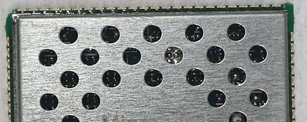
NS914P400
Sep 25, 2014Pico 900MHz 1W FHSS/400MHz 2W License Band Module
Equipment Class
DSS - Part 15 Spread Spectrum Transmitter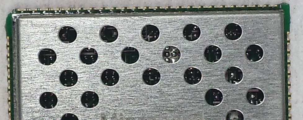
NS913P900
Sep 09, 2013Pico 900 MHz 1W FHSS Module
Equipment Class
DSS - Part 15 Spread Spectrum Transmitter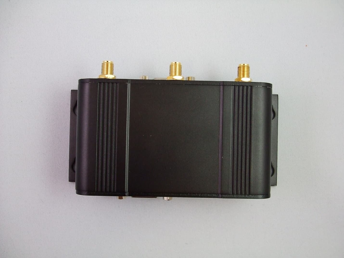
NS9IPN4GNBG30
Apr 22, 2013IPn4G 4G LTE Cellular Ethernet Bridge/Serial Gateway
Equipment Class
JBP - Part 15 Class B Computing Device Peripheral