NS999P2
Microhard Systems Inc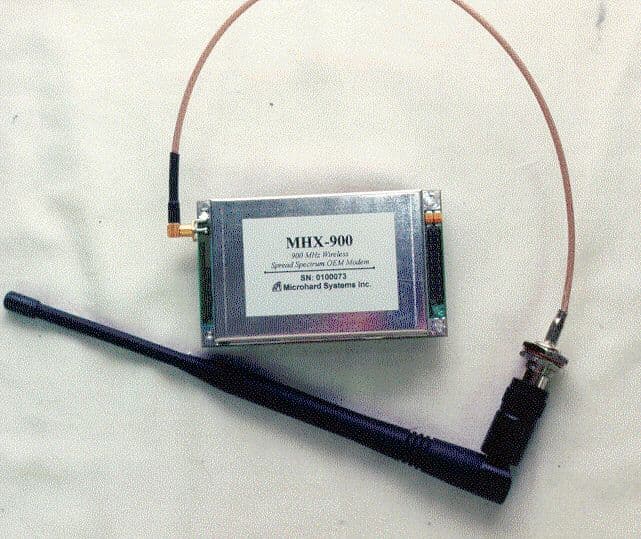
Click to zoom
Application Details
- Equipment Class
- DSS - Part 15 Spread Spectrum Transmitter
- Date of Grant
- Jul 07, 1999
- Application Purpose
- Original Equipment
- Date of Application
- May 11, 1999
- Frequency Range
- 902.50000000 - 927.75000000
- Company
- Microhard Systems Inc
- Country
- Canada
Documents & Files
Document Text
Text extracted from the exhibit documents filed with the FCC. Open a document above to read the original.
Users Manual
Operating Manual 900 MHz Wireless Spread-Spectrum OEM Modem Revision 03 - May 12, 1999 Microhard Systems Inc. has made every effort to assure that this document is accurate and complete. However, the company reserves the right to make changes or enhancements to the manual and/or the product described herein at any time and without notice. Furthermore, Microhard Systems Inc. assumes no liability resulting from any omissions in this document, or out of the application or use of the device described herein. Microhard Systems Inc. Leaders in Wireless Telecom MHX-900 Operating Manual: Contentsi Contents 1.Introduction 1.0Product Overview........................................................................................................................................................ 1 1.1Features........................................................................................................................................................................ 1 1.2About this Manual....................................................................................................................................................... 2 2.Initial Setup and Configuration 2.0Unpacking and Inspection............................................................................................................................................ 3 2.1Additional Requirements............................................................................................................................................. 3 2.2Connectors and Indicators........................................................................................................................................... 3 2.3Configuration............................................................................................................................................................... 5 2.4Checking the Link.........................................................................................................................................................6 3.Configuration Options 3.0Command Line Interface.............................................................................................................................................. 7 3.1AT Commands............................................................................................................................................................. 8 A - Answer....................................................................................................................................................................8 D - Dial........................................................................................................................................................................ 8 E - Command Echo...................................................................................................................................................... 8 I - Identification........................................................................................................................................................... 8 O - Online Mode.......................................................................................................................................................... 8 Q - Quiet Mode............................................................................................................................................................ 9 V - Result Codes Display............................................................................................................................................. 9 W - Connection Result................................................................................................................................................. 9 Z - Reset Modem and load stored configuration.......................................................................................................... 9 &C - DCD (Data Carrier Detect)................................................................................................................................. 9 &D - DTR (Data Terminal Ready)............................................................................................................................... 9 &F - Load Factory default configuration..................................................................................................................... 9 &K - Handshaking........................................................................................................................................................9 &S - DSR (Data Set Ready)....................................................................................................................................... 10 &V - View Configuration...........................................................................................................................................10 &W - Write Configuration to memory....................................................................................................................... 10 Sxxx? - Read S register value.................................................................................................................................... 10 Sxxx=yyy - Set S register value................................................................................................................................. 10 3.2Command Result Codes............................................................................................................................................. 10 3.3S Registers................................................................................................................................................................. 11 S Register 2 - Escape Code.........................................................................................................................................11 S Register 3 - CR Control Code.......................................…
Text truncated - open the document above for the full version.
Cover Letter(s)
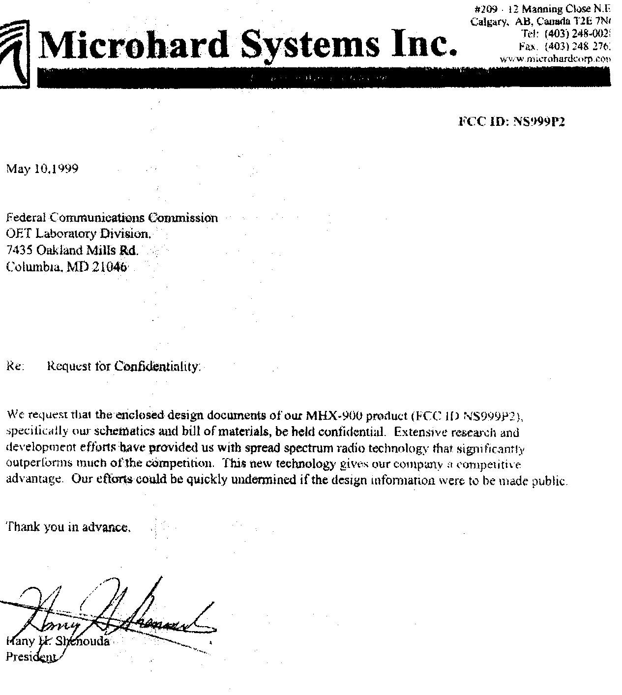
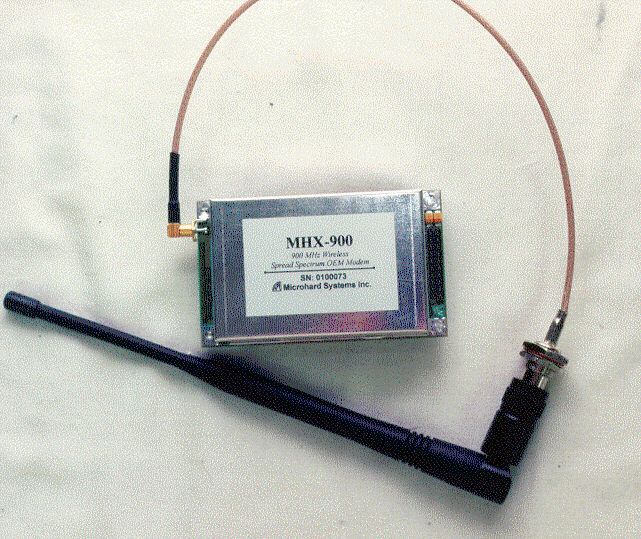
May 12, 1999 Federal Communications Commission 7435 Oakland Mills Road Columbia, MD 21046 ATTN: Applications Examining Division RE: Microhard Systems, Inc., Certification Application; FCCID: NS999P2 Gentlemen: Please find the enclosed application for Certification of a Part 15 Frequency Hopping Spread Spectrum Transmitter module. The Model MHX-900 Embedded Wireless Modem is designed to meet the FCC definition of a SST module. These aspects include RF shielding, buffered data input, power regulation (operates off existing +5 volts rail), unique antenna connector (12" length cable with SMC to reverse gender TNC connectors provided with antenna), FCC testing performed with module in stand-alone configuration and outside of case, and properly labeled with FCCID and interference statement. The MHX-900 does not have a data I/O connector attached to the module, but rather a connection header. Although it contains a modem module along with the radio module, it is up to the actual finished product into which this device is embedded, to provide a data connector. Therefore the MHX-900 is not considered to be a Digital Device Peripheral. The 0.23 meter safe distance limit for 1 mW/cm RF exposure, to be referenced in the user manual page 27, was calculated from FCC OET 65 Appendix B, Table 1B Guidlines for General Population/Uncontrolled Exposure. This calculation was based on the highest EIRP possible from the system, considering maximum power and antenna gain. The formula used was: S = (Po*G)/(4*pi*r^2) Your consideration is much appreciated. Sincerely, Steven Dayhoff Chief Engineer
ID Label/Location Info
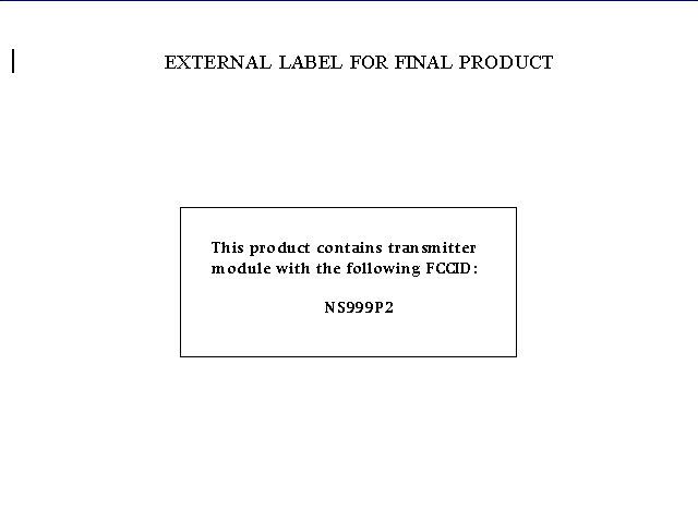
FCCID LABEL AND LOCATION
RF Exposure Info
The following statement will be presented in the MHX-900 User Manual, page 27: WARNING In order to comply with the FCC adopted RF exposure requirements, this transmitter system will be installed by the manufacturer's resaler professional. Installation of the high gain yagi antennas must be performed in a manner that will provide at least 0 .23 meters clearance from the front radiating apperature, to any personnel such as employee or member of the public.
RF Exposure Info
May 12, 1999 Federal Communications Commission 7435 Oakland Mills Road Columbia, MD 21046 ATTN: Applications Examining Division RE: Microhard Systems, Inc., Certification Application; FCCID: NS999P2 Gentlemen: Please find the enclosed application for Certification of a Part 15 Frequency Hopping Spread Spectrum Transmitter module. The Model MHX-900 Embedded Wireless Modem is designed to meet the FCC definition of a SST module. These aspects include RF shielding, buffered data input, power regulation (operates off existing +5 volts rail), unique antenna connector (12" length cable with SMC to reverse gender TNC connectors provided with antenna), FCC testing performed with module in stand-alone configuration and outside of case, and properly labeled with FCCID and interference statement. The MHX-900 does not have a data I/O connector attached to the module, but rather a connection header. Although it contains a modem module along with the radio module, it is up to the actual finished product into which this device is embedded, to provide a data connector. Therefore the MHX-900 is not considered to be a Digital Device Peripheral. The 0.23 meter safe distance limit for 1 mW/cm RF exposure, to be referenced in the user manual page 27, was calculated from FCC OET 65 Appendix B, Table 1B Guidlines for General Population/Uncontrolled Exposure. This calculation was based on the highest EIRP possible from the system, considering maximum power and antenna gain. The formula used was: S = (Po*G)/(4*pi*r^2) Your consideration is much appreciated. Sincerely, Steven Dayhoff Chief Engineer
RF Exposure Info
RF Exposure Calculations: The following information provides the minimum seperation distance for each of the antennas provided with the MHX-900 module, as calculated fromFCC OET 65 Appendix B, Table 1B Guidlines for General Population/Uncontrolled Exposure. This calculation is based on the highest EIRP possible from the system, considering maximum power and antenna gain. The formula used was: S = (Po*G)/(4*pi*r^2) Where S = 0.6 mW/cm^2 for 902 MHz (from F/1500) Where Po = 100 mW for Yagi antennas (max. power set at factory) Where Po = 1.0 Watt for Omni antennas (max. power user configurable) For: 14 dB Yagi Antenna - Sinclabs - SUY-90213 .......r=18cm 12 dB Yagi Antenna - Sinclabs - SUY-90211 .......r=15cm 8 dB Yagi Antenna - Sinclabs - SUY-90207 ....... r = 9 cm 2.5 dB Omni Antenna - 900 MHz Rubber Ducky ......r=15cm 5 dB Omni Antenna - Sinclabs ....................r = 20 cm The following statement will be presented in the MHX-900 User Manual, page 27: WARNING In order to comply with the FCC adopted RF exposure requirements, this transmitter system will be installed by the manufacturer's resaler professional. Installation of the high gain yagi antennas must be performed in a manner that will provide at least 18 cm clearance from the front radiating apperature, to any personnel such as employee or member of the public. Installation of the omni whip antennas must be performed in a manner that will provide at least 20 cm clearance from the whip, to any personnel such as employee or member of the public.
RF Exposure Info
RF Exposure Calculations: The following information provides the minimum seperation distance for each of the antennas provided with the MHX-900 module, as calculated fromFCC OET 65 Appendix B, Table 1B Guidlines for General Population/Uncontrolled Exposure. This calculation is based on the highest EIRP possible from the system, considering maximum power and antenna gain. The formula used was: S = (Po*G)/(4*pi*r^2) Where S = 0.6 mW/cm^2 for 902 MHz (from F/1500) Where Po = 100 mW for Yagi antennas (max. power set at factory) Where Po = 1.0 Watt for Omni antennas (max. power user configurable) For: 14 dB Yagi Antenna - Sinclabs - SUY-90213 .......r=18cm 12 dB Yagi Antenna - Sinclabs - SUY-90211 .......r=15cm 8 dB Yagi Antenna - Sinclabs - SUY-90207 ....... r = 9 cm 2.5 dB Omni Antenna - 900 MHz Rubber Ducky ......r=15cm 5 dB Omni Antenna - Sinclabs ....................r = 20 cm The following statement will be presented in the MHX-900 User Manual, page 27: WARNING In order to comply with the FCC adopted RF exposure requirements, this transmitter system will be installed by the manufacturer's resaler professional. Installation of all antennas must be performed in a manner that will provide at least 20 cm clearance from the front radiating apperature, to any personnel such as employee or member of the public. .
Test Report
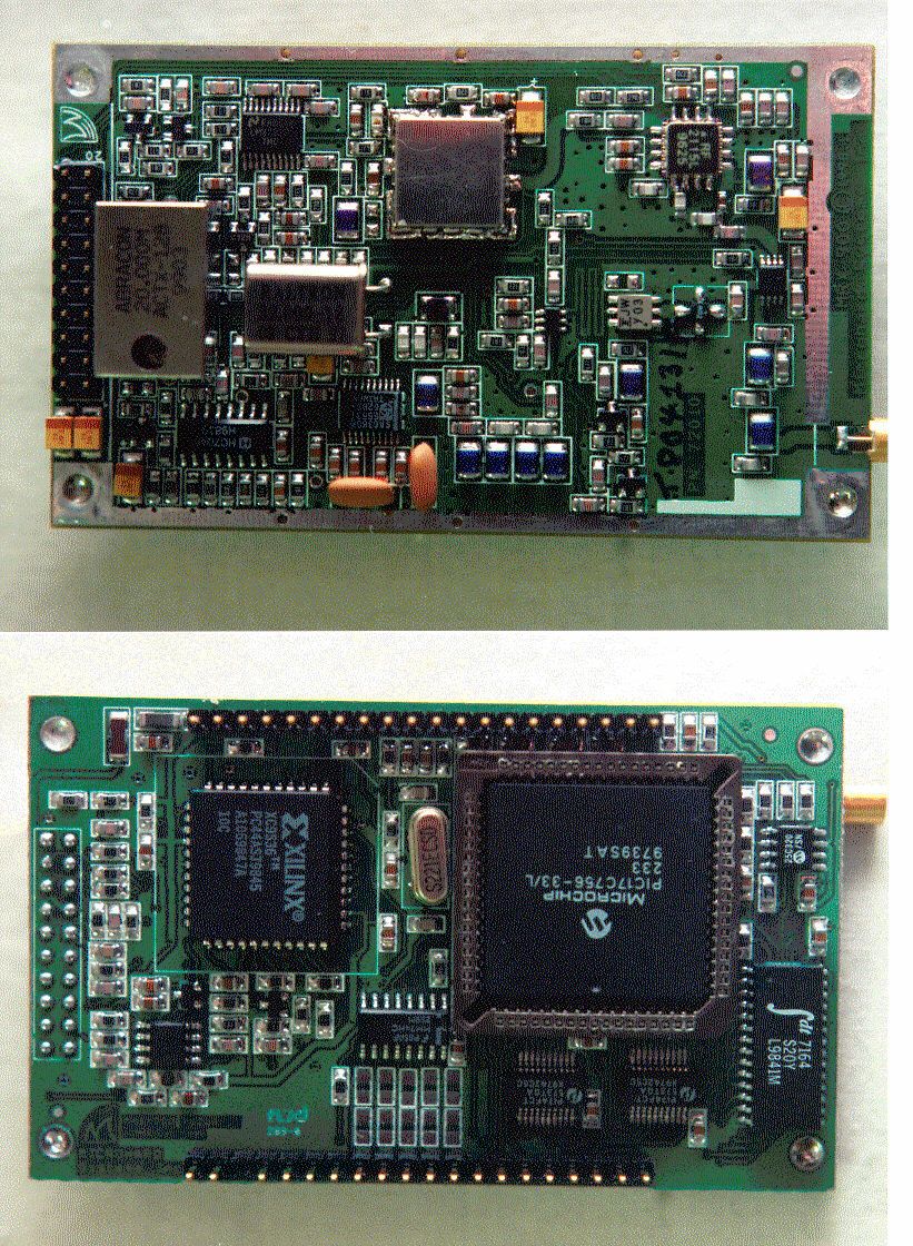
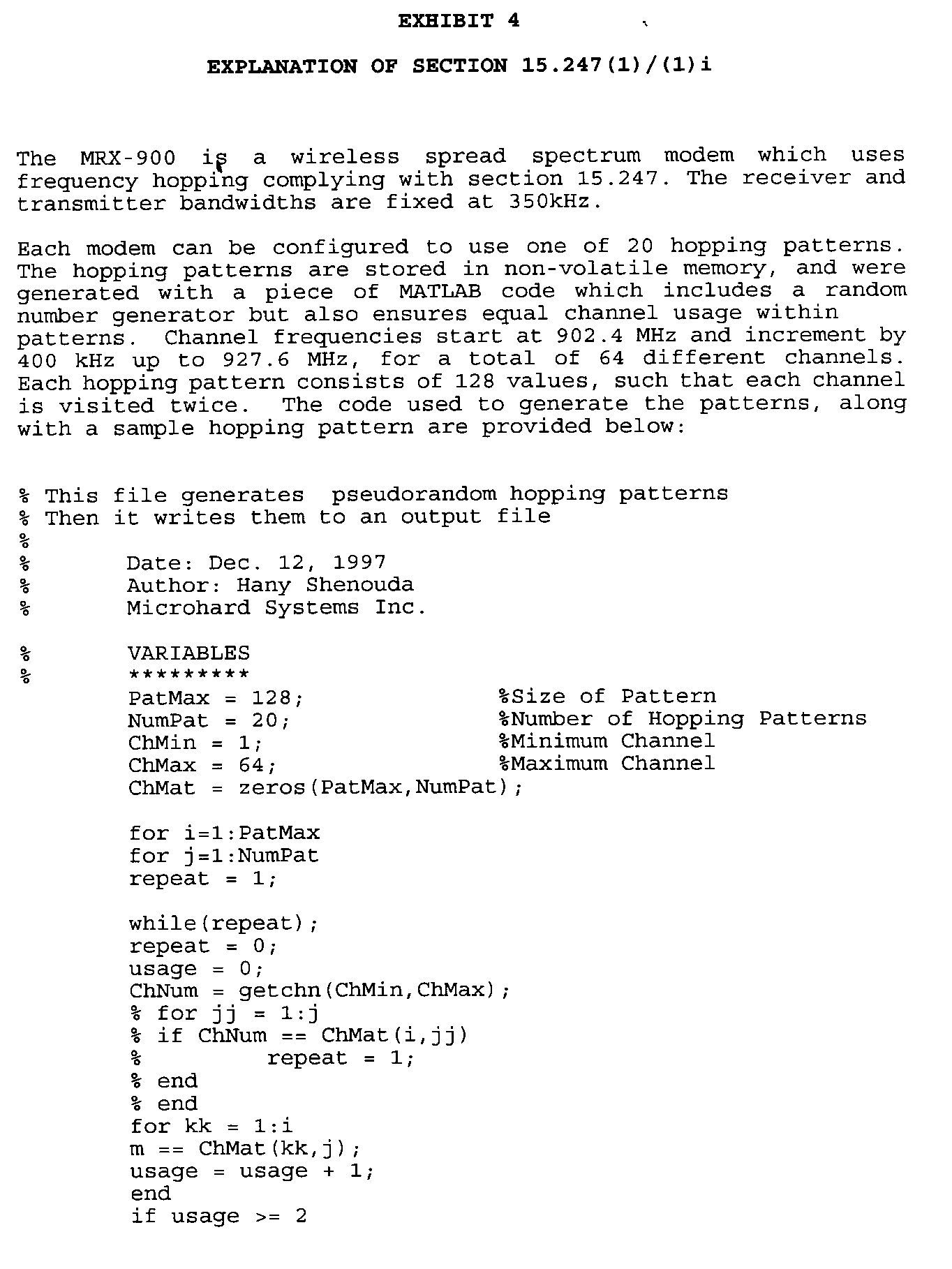
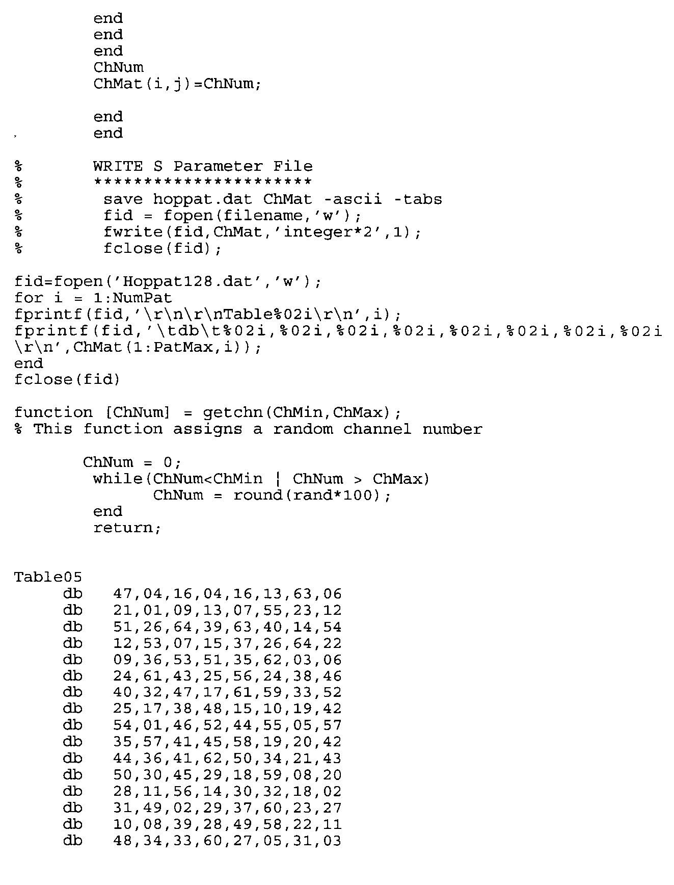
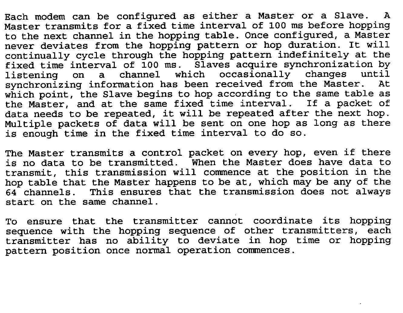
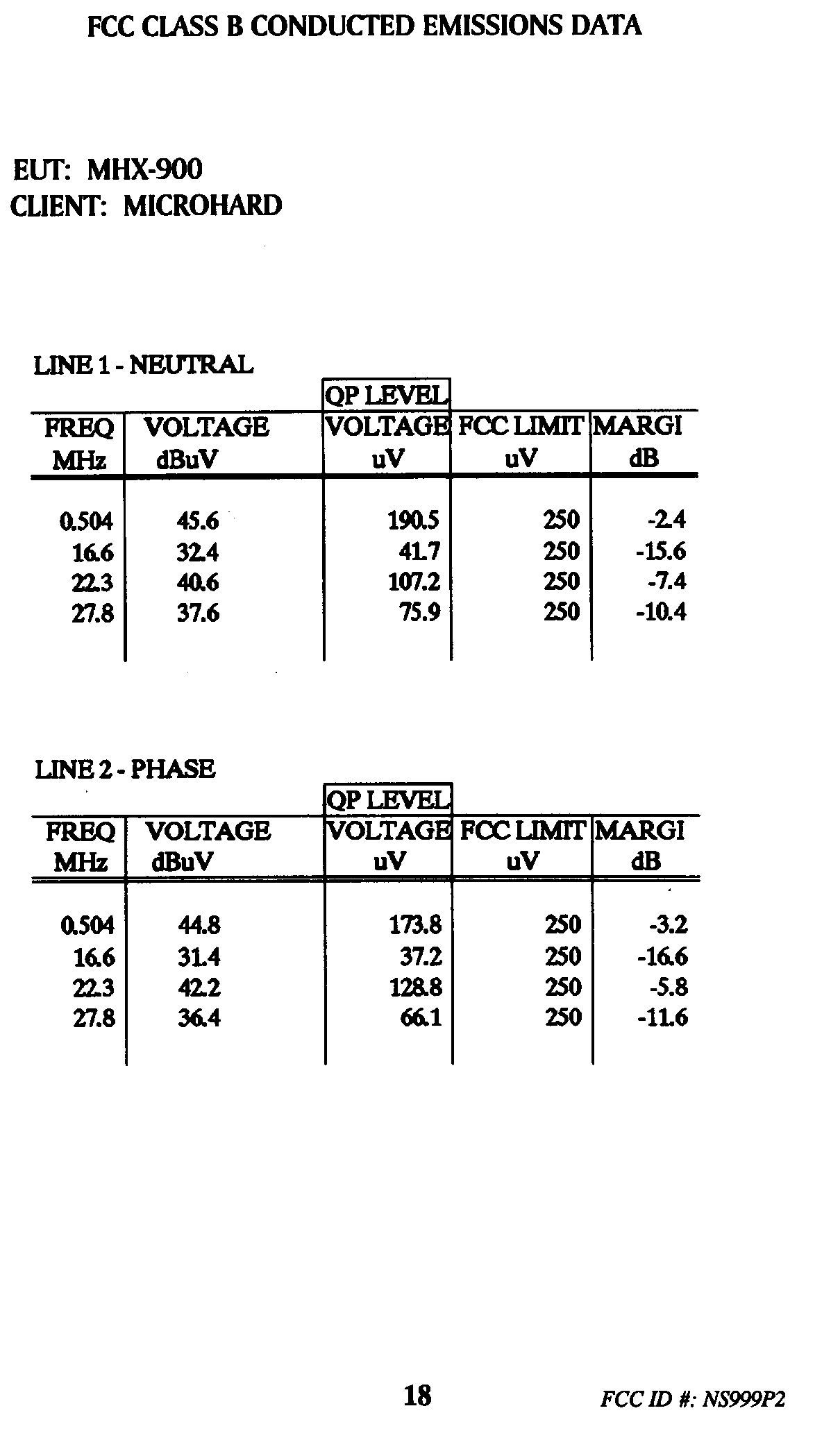
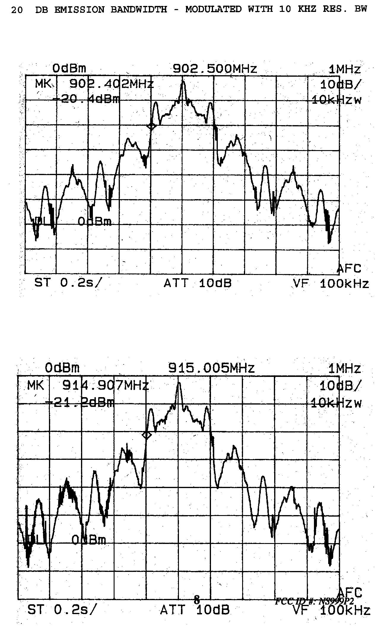
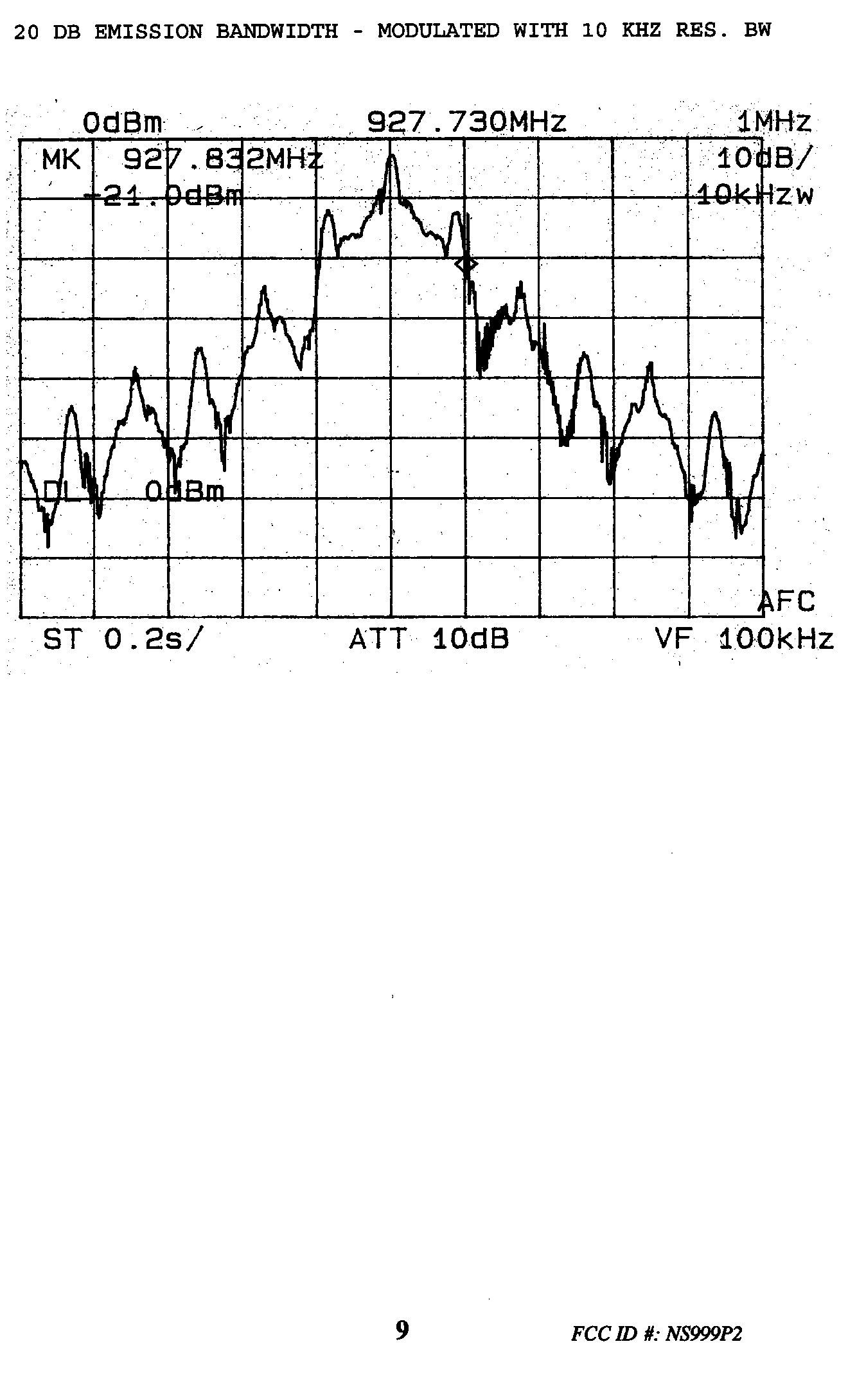
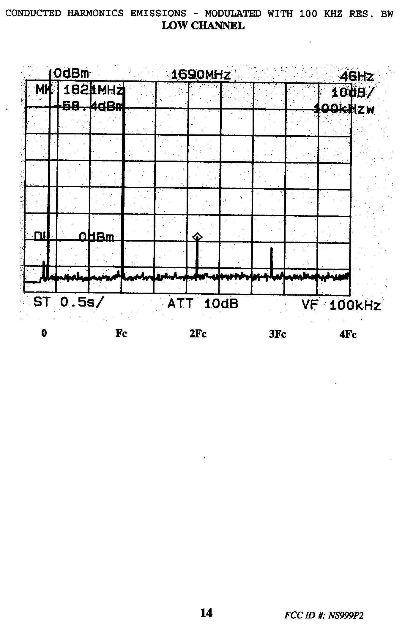
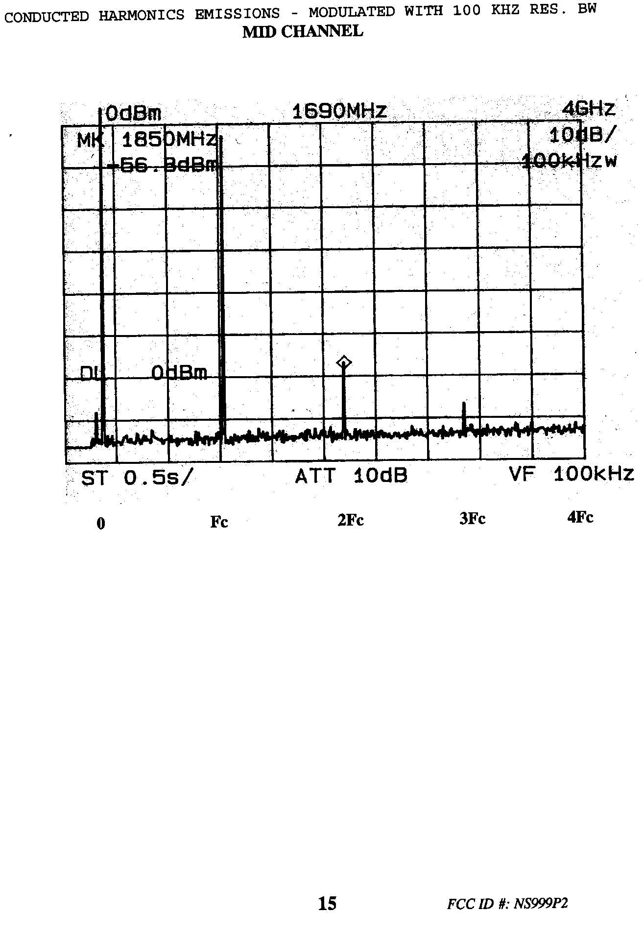
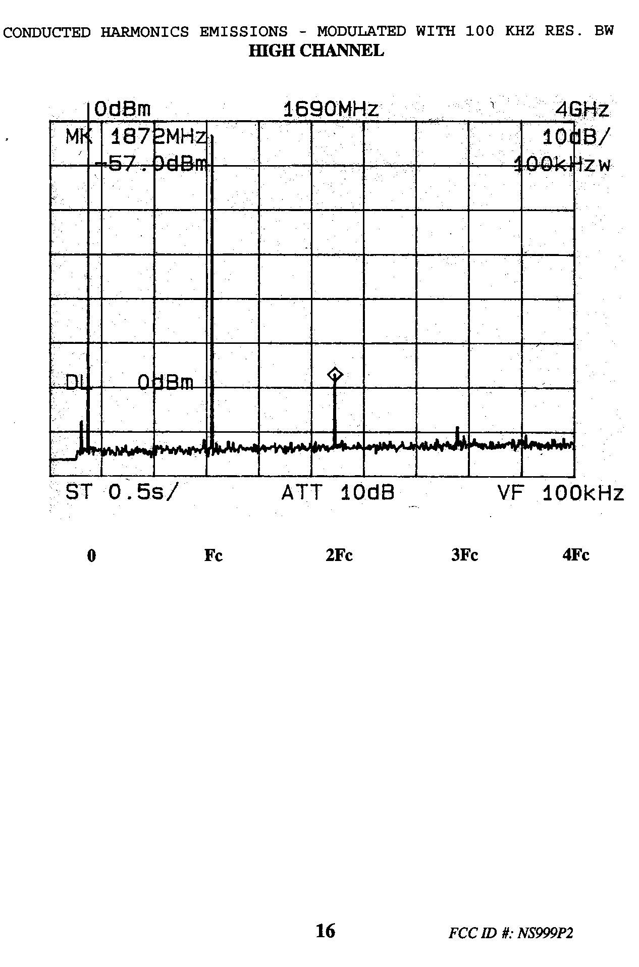
NATIONAL CERTIFICATION LABORATORY 8370 Court Avenue, Suite B-1 Ellicott City MD 21043 (410) 461-5548 FCC REPORT OF RADIO INTERFERENCE for Microhard Systems Inc #209 - 12 Manning Close N.E. Calgary, Alberta Canada FCC ID: NS999P2 May 13, 1999 TABLE OF CONTENTS Application Form 731 FCC Label Drawing and Location 1.0 Introduction 1.1 Summary 2.0 Description of Equipment Under Test (EUT) 3.0 Test Program 4.0 Test Configuration 5.0 Conducted Emissions Scheme 6.0 Radiated Emissions Scheme TABLES Table 1.Support Equipment Table 2.Interface Cables Table 3. Measurement Equipment EXHIBITS Exhibit 1.EUT Photographs Exhibit 2. Schematic Diagram Exhibit 3. User Manual Exhibit 4. Explanation of 15.247(1)/(1)i NCL PROJ.# MICROHARD-500 FCC ID #: NS999P2 3 1.0 Introduction This report has been prepared on behalf of Microhard Systems, Inc., to support the attached Application for Certification of a Part 15 Spread Spectrum Transmitter module. The Equipment Under Test was the Model MHX-900 Wireless Modem Transceiver OEM Module. Radio-Noise Emissions tests were performed according to FCC Public Notice 54797, titled "Guidance on Measurements for Direct Sequence SST" . The measuring equipment conforms to ANSI C63.2 Specifications for Electromagnetic Noise and Field Strength Instrumentation. Testing was performed at National Certification Laboratory in Ellicott City, MD. Site description and site attenuation data have been placed on file with the FCC's Sampling and Measurements Branch. FCC acceptance was granted on May 26, 1993. 1.1 Summary The Microhard Systems, Inc. Model MHX-900 complies with the FCC limits (15.247) for a Frequency Hopping SST. 2.0 Description of Equipment Under Test (EUT) The EUT Features: Reverse TNC Antenna Connector per 15.203 + 30 dBm RF Output Max. 902 - 928 MHz Freq. Range 350 kHz 20 dB Emission Bandwidth 64 Hopping Channels 400 Khz Channel Separation 172.8 kbps Data Rate (Radio Link) FCC ID #: NS999P2 4 115.2 kbps Max Data Rate (DCE) 3.0 Test Program This report contains measurement charts and data as evidence for the following tests performed: 1. (15.247 b) Peak RF output power. 2. (15.247 c) Field strength of harmonics and spurious out-of-band emissions. 3. (15.247 c) RF Antenna Conducted of harmonics and spurious out-of-band emissions. 4. (15.247 a) 20 dB Emission Bandwidth. 5. (15.207) Power Line Conducted Emissions. 4.0 Test Configuration RF antenna conducted output tests such as Bandwidth, Spurious/Harmonics, and Power output, were taken with the transmitter antenna connector feeding directly into the spectrum analyzer via external 30 dB attenuator. The analyzer's internal attenuator was adusted to prevent overloading of the front end. The transmitter is modulated at 115.2 kbps which is the highest available data rate. Field strength measurements were taken with the transmitter feeding a yagi, or omni antenna aimed at the receiving measurement antenna. Testing was performed using the highest gain antenna from each design family (yagi, omni) with the power setting at 1 watt for the omni antenna, and 100 mW for the higher gain yagi. FCC ID #: NS999P2 5 A list of all possible antennas that will be sold with the MRX-900 Wireless Modem is included in Table 1 of this report. PEAK POWER TEST RESULTS Limit: 1.0 watts (30 dBm) Condition: Transmitter is set to a single FM modulated channel Readings from spectrum analyzer with 1 MHz Resolution BW setting: Channel 1: 902.5 MHz - +29.4 dBm Channel 32: 915.0 MHz - +29.8 dBm Channel 64: 927.8 MHz - +29.2 dBm FCC ID #: NS999P2 6 SEE FOLLOWING 3 PLOTS OF MODULATED CARRIER / PEAK POWER MEASUREMENTS - MODULATED WITH 1 MHZ RES. BW FCC ID #: NS999P2 7 FCC ID #: NS999P2 8 PEAK POWER MEASUREMENTS - MODULATED WITH 1 MHZ RES. BW FCC ID #: NS999P2 9 20 dB EMISSION BANDWIDTH Maximum 20 dB BW: 0.500 MHz RBW Setting on S.A.: 10 kHz Condition: Transmitter is set to a single channel FM modulated at FCC ID #: NS999P2 10 115.2 kbps Readings from spectrum analyzer: Channel 1: 902.5 MHz - 196 kHz Channel 32: 915.0 MHz - 196 kHz Channel 64: 927.8 MHz - 204 kHz SEE FOLLOWING PLOT 3 PLOTS OF MODULATED CARRIER FCC ID #: NS999P2 11 20 DB EMISSION BANDWIDTH - MODULATED WITH 10 KHZ RES. BW FCC ID #: NS999P2 12 20 DB EMISSION BANDWIDTH - MODULATED WITH 10 KHZ RES. BW FCC ID #: NS999P2 13 FCC ID #: NS999P2 14 RF ANTENNA CONDUCTED SPURIOUS/HARMONICS EMISSIONS Limit: 20 dB below Carrier Level Measured with 100 kHz RBW RBW Setting on S.A.: 100 kHz Condition: Transmitter is set to a single FM modulated channel. RF power = 30 dBm Three separate Measurements are performed to show harmonic and spurious emissions generated with the transmitter tuned to low, FCC ID #: NS999P2 15 middle, and high parts of the spectral range. SEE FOLLOWING 3 PLOTS & DATA TABLES FCC ID #: NS999P2 16 FCC PART 15.247(c) - CONDUCTED SPURIOUS EMISSIONS Frequency of Carrier = 902.5 MHz Limit = 20 dBc Condition: Transmitter is set to a single FM modulated channel. TEST RESULTS LIMIT: -20 dB FROM PEAK CARRIER COMPONENT FREQUENCY (MHZ) RESULT (dB FROM PEAK) HARMONIC 1805.00 - 58.4 HARMONIC 2707.50 - 62.0 HARMONIC 3610.00 - 73.0 HARMONIC 4512.50 - 73.0 HARMONIC 5415.00 - 74.0 HARMONIC 6317.50 - 75.0 HARMONIC 7220.00 - 75.0 HARMONIC 8122.50 - 75.0 HARMONIC 9025.00 - 75.0 FCC ID #: NS999P2 17 FCC PART 15.247(c) - CONDUCTED SPURIOUS EMISSIONS Frequency of Carrier = 915.00 MHz Limit = 20 dBc Condition: Transmitter is set to a single FM modulated channel. TEST RESULTS LIMIT: -20 dB FROM PEAK CARRIER COMPONENT FREQUENCY (MHZ)RESULT (dB FROM PEAK) HARMONIC 1830.00 - 56.8 HARMONIC 2745.00 - 67.0 HARMONIC 3660.00 - 71.0 HARMONIC 4572.00 - 72.0 HARMONIC 5490.00 - 70.0 HARMONIC 6405.00 - 73.0 HARMONIC 7320.00 - 74.0 HARMONIC 8235.00 - 75.0 HARMONIC 9150.00 - 75.0 FCC ID #: NS999P2 18 FCC PART 15.247(c) - CONDUCTED SPURIOUS EMISSIONS Frequency of Carrier = 927.8 MHz Limit = 20 dBc Condition: Transmitter is set to a single FM modulated channel. TEST RESULTS LIMIT: -20 dB FROM PEAK CARRIER COMPONENT FREQUENCY (MHZ)RESULT …
Text truncated - open the document above for the full version.
Contact Information
Applicant
Hany Shenouda(President)
Technical Contact
National Certification LabSteven L Dayhoff
[email protected]410 461 5548
8370 Court Ave., Suite B-1 · Ellicott City, Maryland · United States
Non-Technical Contact
National Certification LabSteven L Dayhoff
[email protected]410 461 5548
Test Firm
National Certification LaboratoryBrian Haghtalab
Technical Specifications
| # | Rule Parts | Frequency Range | Power Output |
|---|---|---|---|
| 1 | 15C | 902.5 MHz - 927.75 MHz | 1 W |
Other Applications from Microhard Systems Inc
NS920N920T
May 28, 2020n920T 2020 900MHz OEM Frequency Hopping/DTS Module
Equipment Class
DSS - Part 15 Spread Spectrum Transmitter
NS915PX2
Jul 01, 2015Pico 2.4GHz High Speed 1W Module
Equipment Class
DTS - Digital Transmission System
NS914P400
Sep 25, 2014Pico 900MHz 1W FHSS/400MHz 2W License Band Module
Equipment Class
DSS - Part 15 Spread Spectrum Transmitter
NS913P900
Sep 09, 2013Pico 900 MHz 1W FHSS Module
Equipment Class
DSS - Part 15 Spread Spectrum Transmitter
NS9IPN4GNBG30
Apr 22, 2013IPn4G 4G LTE Cellular Ethernet Bridge/Serial Gateway
Equipment Class
JBP - Part 15 Class B Computing Device Peripheral