NS9NBG302.4GHz 802.11bg 1W OEM Module
Microhard Systems Inc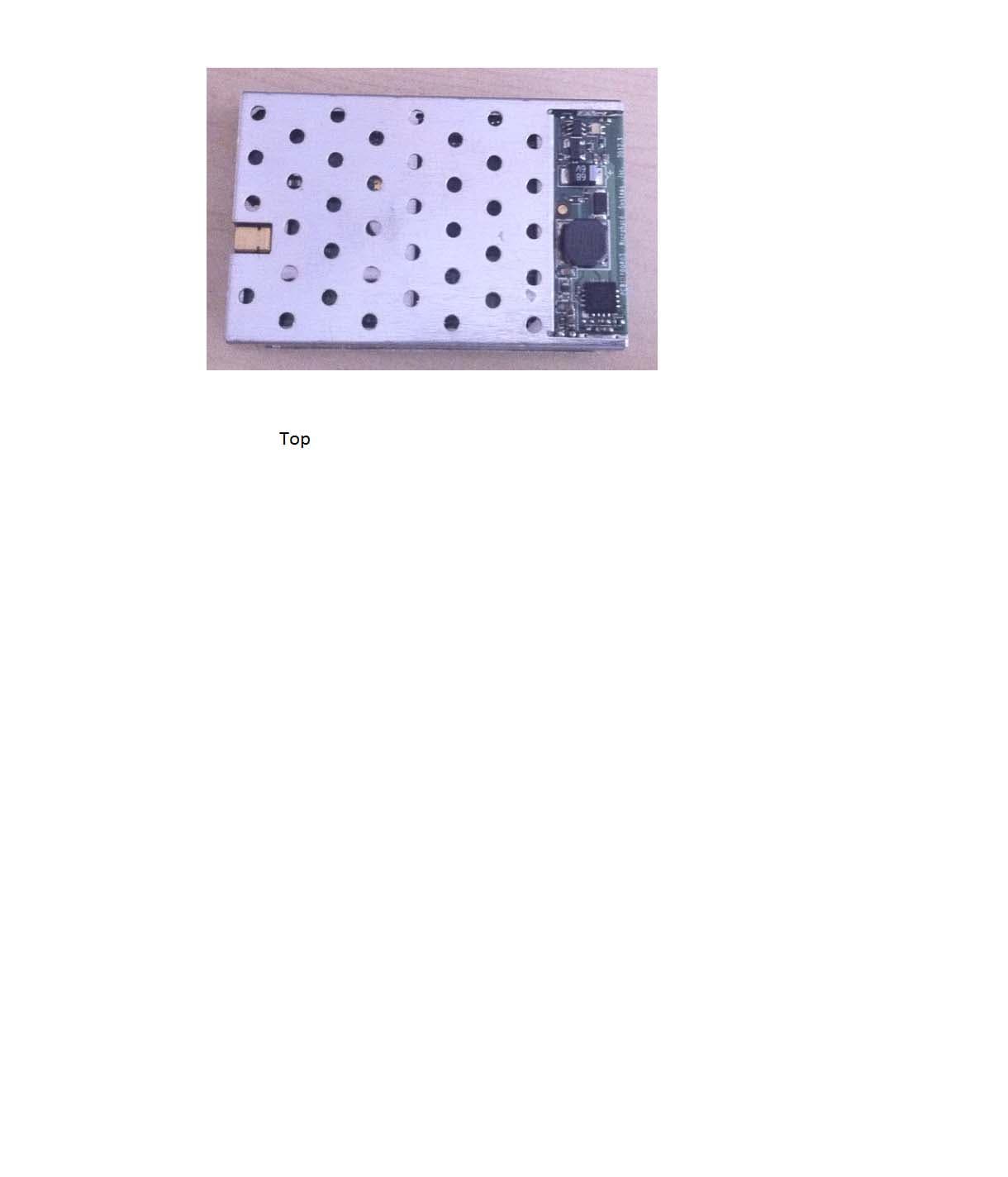
Click to zoom
Application Details
- Equipment Class
- DTS - Digital Transmission System
- Date of Grant
- Jun 06, 2012
- Application Purpose
- Original Equipment
- Date of Application
- Jun 06, 2012
- Equipment Note
- 2.4GHz 802.11bg 1W OEM Module
- Frequency Range
- 2412.00000000 - 2462.00000000
- Company
- Microhard Systems Inc
- Country
- Canada
Documents & Files
Document Text
Text extracted from the exhibit documents filed with the FCC. Open a document above to read the original.
Users Manual
Operating Manual n802.11bg-30 2.4GHz 802.11bg 1W OEM Module Revision 0.50, June 5, 2012 Phone: (403) 248-0028 Fax: (403) 248-2762 www.microhardcorp.com Model: n802.11bg- 30 Microhard Systems Inc. ii N2420B Operating Manual Warranty Microhard Systems Inc. warrants that each product will be free of defects in material and workmanship for a period of one (1) year for its products. The warranty commences on the date the product is shipped by Microhard Systems Inc. Microhard Systems Inc.’s sole liability and responsibility under this warranty is to repair or replace any product which is returned to it by the Buyer and which Microhard Systems Inc. determines does not conform to the warranty. Product returned to Microhard Systems Inc. for warranty service will be shipped to Microhard Systems Inc. at Buyer’s expense and will be returned to Buyer at Microhard Systems Inc.’s expense. In no event shall Microhard Systems Inc. be responsible under this warranty for any defect which is caused by negligence, misuse or mistreatment of a product or for any unit which has been altered or modified in any way. The warranty of replacement shall terminate with the warranty of the product. Warranty Disclaims Microhard Systems Inc. makes no warranties of any nature of kind, expressed or implied, with respect to the hardware, software, and/or products and hereby disclaims any and all such warranties, including but not limited to warranty of non-infringement, implied warranties of merchantability for a particular purpose, any interruption or loss of the hardware, software, and/or product, any delay in providing the hardware, software, and/or product or correcting any defect in the hardware, software, and/or product, or any other warranty. The Purchaser represents and warrants that Microhard Systems Inc. has not made any such warranties to the Purchaser or its agents MICROHARD SYSTEMS INC. EXPRESS WARRANTY TO BUYER CONSTITUTES MICROHARD SYSTEMS INC. SOLE LIABILITY AND THE BUYER’S SOLE REMEDIES. EXCEPT AS THUS PROVIDED, MICROHARD SYSTEMS INC. DISCLAIMS ALL WARRANTIES, EXPRESS OR IMPLIED, INCLUDING ANY WARRANTY OF MERCHANTABILITY OR FITNESS FOR A PARTICULAR PROMISE. MICROHARD SYSTEMS INC. PRODUCTS ARE NOT DESIGNED OR INTENDED TO BE USED IN ANY LIFE SUPPORT RELATED DEVICE OR SYSTEM RELATED FUNCTIONS NOR AS PART OF ANY OTHER CRITICAL SYSTEM AND ARE GRANTED NO FUNCTIONAL WARRANTY. Indemnification The Purchaser shall indemnify Microhard Systems Inc. and its respective directors, officers, employees, successors and assigns including any subsidiaries, related corporations, or affiliates, shall be released and discharged from any and all manner of action, causes of action, liability, losses, damages, suits, dues, sums of money, expenses (including legal fees), general damages, special damages, including without limitation, claims for personal injuries, death or property damage related to the products sold hereunder, costs and demands of every and any kind and nature whatsoever at law. IN NO EVENT WILL MICROHARD SYSTEMS INC. BE LIABLE FOR ANY INDIRECT, SPECIAL, CONSEQUENTIAL, INCIDENTAL, BUSINESS INTERRUPTION, CATASTROPHIC, PUNITIVE OR OTHER DAMAGES WHICH MAY BE CLAIMED TO ARISE IN CONNECTION WITH THE HARDWARE, REGARDLESS OF THE LEGAL THEORY BEHIND SUCH CLAIMS, WHETHER IN TORT, CONTRACT OR UNDER ANY APPLICABLE STATUTORY OR REGULATORY LAWS, RULES, REGULATIONS, EXECUTIVE OR ADMINISTRATIVE ORDERS OR DECLARATIONS OR OTHERWISE, EVEN IF MICROHARD SYSTEMS INC. HAS BEEN ADVISED OR OTHERWISE HAS KNOWLEDGE OF THE POSSIBILITY OF SUCH DAMAGES AND TAKES NO ACTION TO PREVENT OR MINIMIZE SUCH DAMAGES. IN THE EVENT THAT REGARDLESS OF THE WARRANTY DISCLAIMERS AND HOLD HARMLESS PROVISIONS INCLUDED ABOVE MICROHARD SYSTEMS INC. IS SOMEHOW HELD LIABLE OR RESPONSIBLE FOR ANY DAMAGE OR INJURY, MICROHARD SYSTEMS INC.'S LIABILITY FOR ANYDAMAGES SHALL NOT EXCEED THE PROFIT REALIZED BY MICROHARD SYSTEMS INC. ON THE SALE OR PROVISION OF THE HARDWARE TO THE CUSTOMER. Proprietary Rights The Buyer hereby acknowledges that Microhard Systems Inc. has a proprietary interest and intellectual property rights in the Hardware, Software and/or Products. The Purchaser shall not (i) remove any copyright, trade secret, trademark or other evidence of Microhard Systems Inc.’s ownership or proprietary interest or confidentiality other proprietary notices contained on, or in, the Hardware, Software or Products, (ii) reproduce or modify any Hardware, Software or Products or make any copies thereof, (iii) reverse assemble, reverse engineer or decompile any Software or copy thereof in whole or in part, (iv) sell, transfer or otherwise make available to others the Hardware, Software, or Products or documentation thereof or any copy thereof, except in accordance with this Agreement. N2420B Operating Manual: Contents iii n802.11bg-30 Regulatory Requirements WARNING: To satisfy FCC RF exposure requirements for both base and mobile a separation distance of 23 cm or more should be maintained between the antenna of this device and persons during device operation. To ensure compliance, operations at closer than this distance is not recommended. The antenna used for this transmitter must not be co-located in conjunction with any other antenna or transmitter. WARNING: Changes or modifications not expressly approved by Microhard Systems Inc. could void the user’s authority to operate the equipment. This device has been tested with MMCX and Reverse Polarity SMA connectors with the antennas listed in Appendix A When integrated in OEM products, fixed antennas require installation preventing end-users from replacing them with non-approved antennas. Antennas not listed in the tables must be tested to comply with FCC Section 15.203 (unique antenna connectors) and Section 15.247 (emissions). WARNING: To ensure compliance with all non-transmitter functions the host manufacturer is responsible for ensuring compliance with the module(s) installed and fully operational. For example, if a host …
Text truncated - open the document above for the full version.
Attestation Statements
Tel: (403) 248-0028 Fax: (403) 248-2762 E-mail: [email protected] www.microhardcorp.com Leaders in Wireless Telecom May 12, 2012 FEDERAL COMMUNICATIONS COMMISSION 7435 Oakland Mills Road Columbia, MD 21046 U.S.A. Re: Class B Verification Applicant: Microhard Systems Inc. Product: 2.4GHz 802.11bg 1W OEM Module Model: n802.11bg-30 FCC ID: NS9NBG30 Dear Sir/Madam, We, the undersigned, hereby attest to the fact that we will apply the Verification Authorization procedure to the Class B Unintentional Radiator portion. Best Regards, Sincerely, Hany Shenouda Director of Engineering Microhard Systems Inc.
Attestation Statements
Tel: (403) 248-0028 Fax: (403) 248-2762 E-mail: [email protected] www.microhardcorp.com Leaders in Wireless Telecom May 12, 2012 FEDERAL COMMUNICATIONS COMMISSION 7435 Oakland Mills Road Columbia, MD 21046 U.S.A. Subject: Request for Modular Approval Applicant: Microhard Systems Inc. Product: 2.4GHz 802.11bg 1W OEM Module Model: n802.11bg-30 FCC ID: NS9NBG30 Dear Sir/Madam, We, Microhard Systems Inc., request modular approval included below is a clarification on the modular compliance. Hany Shenouda Director of Engineering Microhard Systems Inc. Tel: (403) 248-0028 Fax: (403) 248-2762 E-mail: [email protected] www.microhardcorp.com Leaders in Wireless Telecom Requirements for Modular TransmittersManufacturer’s Clarification (a) In order to be considered a transmitter module, the device must be complete RF transmitter, i.e., it must have its own reference oscillator (e.g., VCO), antenna, etc.... The only connectors to the module, if any, may be power supply and modulation/data inputs The transmitter is completed with its own reference oscillator, antenna. Only connectors provide are dc supply, data and rf ports are provided with the modular transmitter (b) Compliance with FCC RF Exposure requirements may, in some instances, limit the output power of a module and/or the final applications in which the approved module may be employed The radio is intended for use in mobile and fixed applications. A minimum of 23cm separation distance is required from any user to meet FCC RF Exposure requirement (c) While the applicant for a device into which an authorized module is installed is not required to obtain a new authorization for the module, this does not preclude the possibility that some other form of authorization or testing may be required for the device (e.g., a WLAN into which the authorized module is installed still be authorized as PC peripheral, subject to the appropriate equipment authorization) Instructions are provided in the user manual for the integrators to comply with FCC Part15, Subpart B, and any other applicable FCC requirements. (d) In the case of a modular transceiver, the modular approval policy only applies to the transmitter portion of such devices. Pursuant to section 15.101(b), the receiver portion will either be subject to Verification, or it will not be subject to any authorization requirements (unless if is a Scanning Receiver, in which case it is also subject to Certification, pursuant to Section 15.101(a) The receiver is verified. (e) The holder of the grant of equipment authorization (Grantee) of the module is responsible for the compliance of the module in its final configuration, provided that the OEM, integrator, and /or end user has complied with all of the instructions provided by the Grantee which indicate installation and/or operating conditions necessary for compliance. End-users must comply with the following instruction sated in the users’ manual: - Labeling requirement for equipment using this modular transmitter. - RF Exposure compliance with FCC Rules 2.1091 and 1.1307 when the radio is used in a mobile or base system - Other Instructions provided by the manufacturer for third party integrators as stated in the User manual. Requirements for Modular TransmittersManufacturer’s Clarification 1. The modulator transmitter must have its own RF shielding. This is intended to ensure that the module does not have to reply upon the shielding provided by the device into which it is installed in order for all modular transmitter emissions to comply with Part 15 limits. It is also intended to prevent coupling between the RF circuitry of the module and any wires or circuits in the device into which the module is installed. Such coupling may result in noncompliant operation. The modular transmitter has its own RF shielding Tel: (403) 248-0028 Fax: (403) 248-2762 E-mail: [email protected] www.microhardcorp.com Leaders in Wireless Telecom 2. The modular transmitter must have buffered modulation/data inputs (if such inputs are provided) to ensure that the module will comply with Part 15 requirements under conditions of excessive data rates or over modulation. The modular transmitter has buffered modulation/data inputs 3. The modular transmitter must have its own power supply regulation. This is intended to ensure that the module will comply with Part 15 requirements regardless of the design of the power supplying circuitry in the device into which the module is installed. The modular transmitter has its own analog and digital power supply regulation. 4. The modular transmitter must comply with the antenna requirements of section 15.203 and 15.204(c). The antenna must either be permanently attached or employ a “unique” antenna coupler (at all connections between the module and the antenna, including the cable). Any antenna used with the module must be approved with the module, either at the time of initial authorization or through a Class II permissive change. The “professional installation” provision of Section 15.203 may not be applied to modules but can apply to limited modular approvals under paragraph (b) of this section. The radio and its associated antennas are provided with a unique coupling antenna connector ‘MMCX’. 5. The modular transmitter must be tested in a stand-alone configuration, i.e., the module must not be inside another device during testing. This is intended to demonstrate that the module is capable of complying with Part 15 emission limits regardless of the device into which it is eventually installed. Unless the transmitter module will be battery powered, it must comply with the AC conducted requirements found in Section 15.207. AC or DC power lines and data input/output lines connected to the module must not contain ferrites, unless they will marketed with the module (see Section 15.27(a)). The length of these lines shall be length typical of actual use or, if that length is unknown, at least 10 centimeters to insure that there is …
Text truncated - open the document above for the full version.
Cover Letter(s)
June 4, 2012 Ultratech Engineering Labs, Inc. 3000 Bristol Circle Oakville, Ontario L6H 6G4 Subject: FCC Certification Authorization Application Under FCC Part 15, Subpart C, Section 15.247 - Digital Modulation Systems (DTS). Applicant: Microhard Systems Inc. Product: 2.4GHz 802.11bg 1W OEM Module Model No.: n802.11bg-30 FCC ID: NS9NBG30 Dear Sir/Madam: As appointed agent for Microhard Systems Inc., we submit the application for certification of the above product. Kindly review all files uploaded to your electronic filing site. NOTE: This application is subject to modular approval; see Applicant’s cover letter requesting for modular approval. If you have any queries, please do not hesitate to contact us. Yours truly, Dan Huynh Dan Huynh Authorized Agent UltraTech Group of Labs FCC TCB & IC CB Ultratech’s Accreditations: 0685 FCC 91038 1309 46390-2049 NvLap Lab Code 200093-0 SL2-IN-E-1119R Korea KCC-RRL CA2049 3000 Bristol Circle, Oakville, Ontario, Canada L6H 6G4 Tel.: (905) 829-1570 Fax.: (905) 829-8050 Website: www.ultratech-labs.com Email: [email protected]
Cover Letter(s)
Tel: (403) 248-0028 Fax: (403) 248-2762 E-mail: [email protected] www.microhardcorp.com Leaders in Wireless Telecom May 12, 2012 FEDERAL COMMUNICATIONS COMMISSION 7435 Oakland Mills Road Columbia, MD 21046 U.S.A. Re: Authority to Act as an Agent to FCC Applicant: Microhard Systems Inc. Product: 2.4GHz 802.11bg 1W OEM Module Model: n802.11bg-30 FCC ID: NS9NBG30 Dear Sir/Madam, I hereby appoint UltraTech Engineering Labs Inc. (UltraTech) to act as my agent in preparation of this application to F.C.C. for authourization of equipment under F.C.C. Rules. This authorization is valid for 180days from the date of this letter. The applicant hereby certify that neither the applicant nor any party to the application is subject to a denial of Federal benefits, that include FCC benefits, pursuant to Section 5301 of the Anti-Drug Abuse Act of 1988, 21 U.S.C. §862 because of a conviction for possession or distribution of a controlled substance. See 47 CFR 1.2002(b) for the definition of a “party” for these purposes. Sincerely, Hany Shenouda Director of Engineering Microhard Systems Inc.
Cover Letter(s)
Tel: (403) 248-0028 Fax: (403) 248-2762 E-mail: [email protected] www.microhardcorp.com Leaders in Wireless Telecom May 12, 2012 FEDERAL COMMUNICATIONS COMMISSION 7435 Oakland Mills Road Columbia, MD 21046 U.S.A. Subject: Request for withholding from public disclosure the schematic diagrams and system block diagrams, parts lists and operational description pursuant to an application for certification. Applicant: Microhard Systems Inc. Product: 2.4GHz 802.11bg 1W OEM Module Model: n802.11bg-30 FCC ID: NS9NBG30 Dear Sir/Madam, We, Microhard Systems Inc., would like to request that the schematic diagrams, system block diagrams, parts list, and operational description, submitted with the application for certification be withheld from public disclosure as per Section 0.459 of FCC Rules. This request is made under the provisions of Section 0.457(d) of the Commission's Rules, and Section 552(b)(4) of the Freedom of Information Act. These sections authorize as a withholding from public inspection materials which would be privileged as a matter of law if retained by the person submitting them, and materials which would not customarily be released to the public by that person. If you have any queries, please do not hesitate to contact us: Tel: (403) 248-0028 Fax: (403) 248-2762 Yours truly, Hany Shenouda Director of Engineering Microhard Systems Inc.
ID Label/Location Info
LABEL FORMAT AND LOCATION TOP View 2400 to 2483.5 MHz OEM Module n802.11bg-30 IC: 3143A-NBG30 FCC ID: NS9NBG30 Power: 1W
RF Exposure Info
FCC Part 15, Subpart C, Section 15.247 – DTS Page 155 2.4GHz 802.11bg 1W OEM Module, Model n802.11bg-30 FCC ID: NS912NBG30 ULTRATECH GROUP OF LABS File #: MCRS-046F15C247 3000 Bristol Circle, Oakville, Ontario, Canada L6H 6G4 June 4, 2012 Tel. #: 905-829-1570, Fax. #: 905-829-8050, Email: [email protected] , Website: http://www.ultratech-labs.com All test results contained in this engineering test report are traceable to National Institute of Standards and Technology (NIST) 5.7. RF EXPOSURE REQUIRMENTS [§§ 15.247(i), 1.1310 & 2.1091] The criteria listed in the following table shall be used to evaluate the environmental impact of human exposure to radio-frequency (RF) radiation. FCC 47 CFR § 1.1310: 5.7.1. Method of Measurements Refer to Sections 1.1310, 2.1091 In order to demonstrate compliance with MPE requirements (see Section 2.1091), the following information is typically needed: (1) Calculation that estimates the minimum separation distance (20 cm or more) between an antenna and persons required to satisfy power density limits defined for free space. (2) Antenna installation and device operating instructions for installers (professional/unskilled users), and the parties responsible for ensuring compliance with the RF exposure requirement (3) Any caution statements and/or warning labels that are necessary in order to comply with the exposure limits (4) Any other RF exposure related issues that may affect MPE compliance FCC Part 15, Subpart C, Section 15.247 – DTS Page 156 2.4GHz 802.11bg 1W OEM Module, Model n802.11bg-30 FCC ID: NS912NBG30 ULTRATECH GROUP OF LABS File #: MCRS-046F15C247 3000 Bristol Circle, Oakville, Ontario, Canada L6H 6G4 June 4, 2012 Tel. #: 905-829-1570, Fax. #: 905-829-8050, Email: [email protected] , Website: http://www.ultratech-labs.com All test results contained in this engineering test report are traceable to National Institute of Standards and Technology (NIST) Calculation Method of RF Safety Distance: 22 44r EIRP r GP S Where: P: power input to the antenna in mW EIRP: Equivalent (effective) isotropic radiated power S: power density mW/cm 2 G: numeric gain of antenna relative to isotropic radiator r: distance to centre of radiation in cm 5.7.2. RF Evaluation Evaluation of RF Exposure Compliance Requirements RF Exposure Requirements Compliance with FCC Rules Minimum calculated separation distance between antenna and persons required: *18 cm Manufacturer’ instruction for separation distance between antenna and persons required: 23 cm. Antenna installation and device operating instructions for installers (professional/unskilled users), and the parties responsible for ensuring compliance with the RF exposure requirement Antenna installation and device operating instructions shall be provided to installers to maintain and ensure compliance with RF exposure requirements. Caution statements and/or warning labels that are necessary in order to comply with the exposure limits Refer to User’s Manual for RF Exposure Information. Any other RF exposure related issues that may affect MPE compliance None. *The minimum separation distance between the antenna and bodies of users are calculated using the following formula: RF EXPOSURE DISTANCE LIMITS S EIRP S GP r 44 S = 1.0 mW/cm 2 EIRP = 36.0 dBm = 10 36/10 mW = 3981 mW (Worst Case) (Minimum Safe Distance, r) = cm S EIRP 18 )0.1(4 3981 4
Test Report
2.4GHz 802.11bg 1W OEM Module Model: n802.11bg-30 FCC ID: NS9NBG30 Applicant: Microhard Systems Inc. 150 Country Hills Landing NW Calgary, Alberta Canada T3K 5P3 In Accordance With Federal Communications Commission (FCC) Part 15, Subpart C, Section 15.247 Digital Modulation Systems (DTS) UltraTech's File No.: MCRS-046F15C247 This Test report is Issued under the Authority of Tri M. Luu Vice President of Engineering UltraTech Group of Labs Date: June 4, 2012 Report Prepared by: Dan Huynh Issued Date: June 4, 2012 Tested by: Mr. Hung Trinh Test Dates: April 25 - May 23, 2012 The results in this Test Report apply only to the sample(s) tested, and the sample tested is randomly selected. This report must not be used by the client to claim product endorsement by NVLAP or any agency of the US Government. UltraTech 3000 Bristol Circle, Oakville, Ontario, Canada, L6H 6G4 Tel.: (905) 829-1570 Fax.: (905) 829-8050 Website: www.ultratech-labs.com , Email: [email protected], Email: [email protected] FCC Korea KCC-RRL 91038 1309 46390-2049 NvLap Lab Code 200093-0 SL2-IN-E-1119R CA2049 FCC Part 15, Subpart C, Section 15.247 – DTS Contents i 2.4GHz 802.11bg 1W OEM Module, Model n802.11bg-30 FCC ID: NS9NBG30 ULTRATECH GROUP OF LABS File #: MCRS-046F15C247 3000 Bristol Circle, Oakville, Ontario, Canada L6H 6G4 June 4, 2012 Tel. #: 905-829-1570, Fax. #: 905-829-8050, Email: [email protected] , Website: http://www.ultratech-labs.com All test results contained in this engineering test report are traceable to National Institute of Standards and Technology (NIST) TABLE OF CONTENTS EXHIBIT 1. INTRODUCTION.............................................................................................................................................. 1 1.1. SCOPE ........................................................................................................................................................................ 1 1.2. RELATED SUBMITTAL(S)/GRANT(S) ........................................................................................................................ 1 1.3. NORMATIVE REFERENCES ...................................................................................................................................... 1 EXHIBIT 2. PERFORMANCE ASSESSMENT.................................................................................................................... 2 2.1. CLIENT INFORMATION .............................................................................................................................................. 2 2.2. EQUIPMENT UNDER TEST (EUT) INFORMATION ................................................................................................... 2 2.3. EUT’S TECHNICAL SPECIFICATIONS....................................................................................................................... 3 2.4. ASSOCIATED ANTENNA DESCRIPTIONS ................................................................................................................ 4 2.5. LIST OF EUT’S PORTS............................................................................................................................................... 4 2.6. ANCILLARY EQUIPMENT ........................................................................................................................................... 4 EXHIBIT 3. EUT OPERATING CONDITIONS AND CONFIGURATIONS DURING TESTS............................................... 5 3.1. CLIMATE TEST CONDITIONS.................................................................................................................................... 5 3.2. OPERATIONAL TEST CONDITIONS & ARRANGEMENT FOR TESTS..................................................................... 5 EXHIBIT 4. SUMMARY OF TEST RESULTS ..................................................................................................................... 6 4.1. LOCATION OF TESTS ................................................................................................................................................ 6 4.2. APPLICABILITY & SUMMARY OF EMC EMISSION TEST RESULTS .......................................................................6 4.3. MODIFICATIONS INCORPORATED IN THE EUT FOR COMPLIANCE PURPOSES ................................................ 6 EXHIBIT 5. TEST DATA ..................................................................................................................................................... 7 5.1. POWER LINE CONDUCTED EMISSIONS [§15.207(a)].............................................................................................. 7 5.2. OCCUPIED BANDWIDTH [§ 15.247(a)(2)] ................................................................................................................ 10 5.3. PEAK CONDUCTED OUTPUT POWER - DTS [§ 15.247(b)(3)] ............................................................................... 53 5.4. TRANSMITTER BAND-EDGE & SPURIOUS CONDUCTED EMISSIONS [§ 15.247(d)].......................................... 56 5.5. TRANSMITTER SPURIOUS RADIATED EMISSIONS AT 3 METERS [§§ 15.247(d), 15.209 & 15.205]................ 127 5.6. POWER SPECTRAL DENSITY [§ 15.247(e)] .......................................................................................................... 132 5.7. RF EXPOSURE REQUIRMENTS [§§ 15.247(i), 1.1310 & 2.1091].......................................................................... 155 EXHIBIT 6. TEST EQUIPMENT LIST ............................................................................................................................. 157 EXHIBIT 7. MEASUREMENT UNCERTAINTY............................................................................................................... 158 7.1. LINE CONDUCTED EMISSION MEASUREMENT UNCERTAINTY .......................................................................158 7.2. RADIATED EMISSION MEASUREMENT UNCERTAINTY .................…
Text truncated - open the document above for the full version.
Test Setup Photos
ANNEX 1 - TEST SETUP PHOTOS Microhard Systems Inc. 2.4GHz 802.11bg 1W OEM Module, Model n802.11bg-30 FCC ID: NS9NBG30 A1 - 1 Power Line Conducted Emissions ANNEX 1 - TEST SETUP PHOTOS Microhard Systems Inc. 2.4GHz 802.11bg 1W OEM Module, Model n802.11bg-30 FCC ID: NS9NBG30 A1 - 2 Power Line Conducted Emissions ANNEX 1 - TEST SETUP PHOTOS Microhard Systems Inc. 2.4GHz 802.11bg 1W OEM Module, Model n802.11bg-30 FCC ID: NS9NBG30 A1 - 3 Radiated Emissions @ 3 m ANNEX 1 - TEST SETUP PHOTOS Microhard Systems Inc. 2.4GHz 802.11bg 1W OEM Module, Model n802.11bg-30 FCC ID: NS9NBG30 A1 - 4 Radiated Emissions @ 3 m ANNEX 1 - TEST SETUP PHOTOS Microhard Systems Inc. 2.4GHz 802.11bg 1W OEM Module, Model n802.11bg-30 FCC ID: NS9NBG30 A1 - 5 Radiated Emissions @ 3 m
Contact Information
Applicant
Hany Shenouda(President)
Test Firm
UltraTech Engineering Labs Inc.Tri Luu
Technical Specifications
| # | Rule Parts | Frequency Range | Power Output |
|---|---|---|---|
| 3 | 15C | 2.41 GHz - 2.46 GHz | 991.00 mW |
Other Applications from Microhard Systems Inc
NS920N920T
May 28, 2020n920T 2020 900MHz OEM Frequency Hopping/DTS Module
Equipment Class
DSS - Part 15 Spread Spectrum Transmitter
NS915PX2
Jul 01, 2015Pico 2.4GHz High Speed 1W Module
Equipment Class
DTS - Digital Transmission System
NS914P400
Sep 25, 2014Pico 900MHz 1W FHSS/400MHz 2W License Band Module
Equipment Class
DSS - Part 15 Spread Spectrum Transmitter
NS913P900
Sep 09, 2013Pico 900 MHz 1W FHSS Module
Equipment Class
DSS - Part 15 Spread Spectrum Transmitter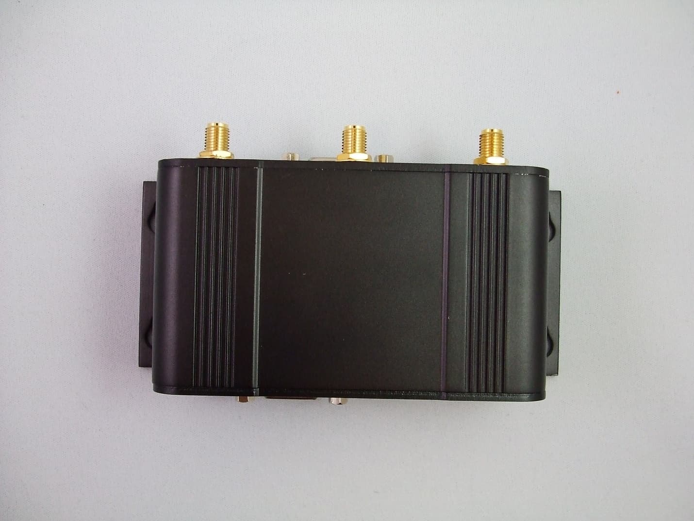
NS9IPN4GNBG30
Apr 22, 2013IPn4G 4G LTE Cellular Ethernet Bridge/Serial Gateway
Equipment Class
JBP - Part 15 Class B Computing Device Peripheral