NT3BDA-1819-60BI-DIRECTIONAL AMPLIFIER
Communication Components Inc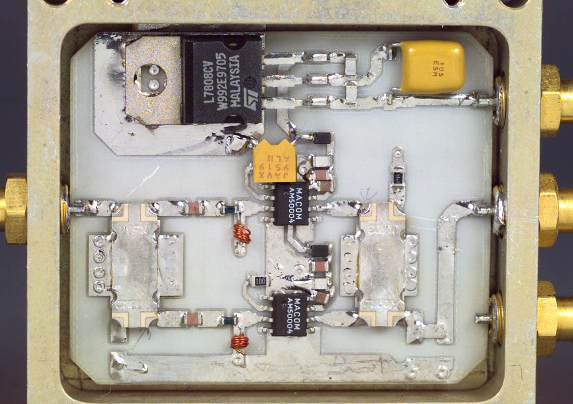
Click to zoom
Application Details
- Equipment Class
- AMP - Amplifier
- Date of Grant
- Oct 25, 1999
- Application Purpose
- Original Equipment
- Date of Application
- May 17, 1999
- Equipment Note
- BI-DIRECTIONAL AMPLIFIER
- Frequency Range
- 1850.00000000 - 1885.00000000
- Company
- Communication Components Inc
- Country
- United States
Documents & Files
Document Text
Text extracted from the exhibit documents filed with the FCC. Open a document above to read the original.
Users Manual
THEORY OF OPERATION The BDA-1819-60 is a bi-directional amplifier. It is designed to exchange radio communications in buildings, basements, tunnels and other RF shielded environments. The BDA improves the sensitivity of base stations in indoor locations where there is a significant amount of cable loss in RF distribution systems. BDA-1819-60 operates in designated PCS bands. It contains two amplifiers providing amplification of RF signals in Up-link and Down-link frequency bands. They are connected to the external cables via frequency selective duplexers in order to attenuate all signals that are not in the designated bands. TECHNICAL DESCRIPTION The BDA-1819-60 bi-directional amplifier provides signal amplification in two separated frequency bands in both directions between two coaxial connector terminals. It is achieved by utilization of two frequency selective duplexers, which direct signals at two frequency bands present at the common port in two outputs. These duplexers provide sufficiently high isolation between two paths to prevent self-oscillation of the system. Detailed block- diagram is shown in Figure 1. The amplifier consists from several gain stages with the low noise stage at the input and medium power stage at the output. All amplifier stages operate at class A linear regime in order to provide the lowest possible intermodulation products. The duplexer serves two purposes: it splits the signal from the common port to two different ports, and it provides frequency selectivity and isolation between two paths. The common port of the first duplexer is called “BASE STATION”. The common port of the other duplexer is called “SERVICE AREA”. Only signals within the frequency range of PCS corresponding Down-link of A-D, B, or C band will be amplified coming from the BASE STATION port and only signals within the corresponding Up-link band will be amplified from the SERVICE AREA port. In this configuration the BDA amplifies signals in the Up-link band in one direction and signals in the Down-link band in the other direction. Physically the BDA block consists of a single compact unit with two RF connectors. It is rugged and can be easily connected during cable installation. It has a moisture proof NEMA 4X enclosure suitable for indoor and outdoor installation with two low noise medium power amplifiers, optional independently controlled Up-link and Down-link attenuators, two duplexers, and optional bias tee’s and AGC circuits. The BDA can be powered by a conventional 110/220 VAC source using an external power supply or alternatively DC voltage can be supplied to the BDA via an external DC input or via center conductor of the RF coax cable. Figure 1 Line Bi -Directional Amplifier BLOCK DIAGRAM Rx/Tx DUPLEXER Rx BPF Tx BPF Rx/Tx DUPLEXER BIAS TEE Rx BPF Tx BPF BIAS TEE AMP AMP Variable Attenuator AMP AMP Variable Attenuator Variable attenuators and AGC are optional AC Power Supply Bias Tee’s are optional INSTALLATION MANUAL for BI-DIRECTIONAL AMPLIFIERS Communication Components Inc. 299 Forest Ave, Paramus, N.J. 07652 Tel: 201-265-8882, Fax: 201-265-8922 TABLE OF CONTENTS 1. Theory of Operation 2. Technical Description 3. Installation Procedure 1. THEORY OF OPERATION The BDA-1819-60 is a bi-directional amplifier. It. is designed to exchange radio communications in buildings, basements, tunnels and other RF shielded environments. The BDA improves the sensitivity of base stations in indoor locations where there is a significant amount of cable loss in RF distribution systems. It contains two amplifiers providing amplification of RF signals in Up-link and Down-link frequency bands. They are connected to the external cables via frequency selective duplexers in order to attenuate all signals that are not in the designated bands. 2. TECHNICAL DESCRIPTION The BDA-1819-60 bi-directional amplifier provides signal amplification in two separate frequency bands in both directions between two coaxial connector terminals. It is achieved by utilization of two frequency selective duplexers, which direct signals at two frequency bands present at the common port in two outputs. These duplexers provide sufficiently high isolation between two paths to prevent self-oscillation of the system. Detailed block- diagram is shown in Figure 1. The amplifier consists from several gain stages with the low noise stage at the input and medium power stage at the output. All amplifier stages operate at class A linear regime in order to provide the lowest possible intermodulation products. The duplexer serves two purposes: it splits the signal from the common port to two different ports, and it provides frequency selectivity and isolation between two paths. The common port of the first duplexer is called “BASE STATION”. The common port of the other duplexer is called “SERVICE AREA”. Only signals within the frequency range of 851-866 MHz band will be amplified coming from the BASE STATION port and only signals within the frequency range of 806-821 MHz band will be amplified from the SERVICE AREA port. In this configuration the BDA amplifies signals in the Up-link band in one direction and signals in the Down-link band in the other direction. Physically the BDA block consists of a single compact unit with two RF connectors. It is rugged and can be easily connected during cable installation. It has a moisture proof NEMA 4X enclosure suitable for indoor and outdoor installation with two low noise medium power amplifiers, optional independently controlled Up-link and Down-link attenuators, two duplexers, and optional bias tee’s. The BDA can be powered by a conventional 110/220 VAC source using a built-in power supply or alternatively DC voltage can be supplied to the BDA via an external DC input or via center conductor of the RF coax cable. Figure 1 Line Bi -Directional Amplifier BLOCK DIAGRAM Rx/Tx DUPLEXER Rx BPF Tx BPF Rx/Tx DUPLEXER BIAS TEE Rx BPF Tx BPF BIAS TEE AMP AMP Variable Attenuator AMP AMP Variable Attenuator Vari…
Text truncated - open the document above for the full version.
Users Manual
INSTALLATION MANUAL for BI-DIRECTIONAL AMPLIFIERS Communication Components Inc. 299 Forest Ave, Paramus, N.J. 07652 Tel: 201-265-8882, Fax: 201-265-8922 TABLE OF CONTENTS 1. Theory of Operation 2. Intended Application 3. Technical Description 4. Installation Procedure 5. Antenna installation safety precautions 1. THEORY OF OPERATION The BDA-1819-60 is a bi-directional amplifier. It. is designed to exchange radio communications in buildings, basements, tunnels and other RF shielded environments. The BDA improves the sensitivity of base stations in indoor locations where there is a significant amount of cable loss in RF distribution systems. It contains two amplifiers providing amplification of RF signals in Up-link and Down-link frequency bands. They are connected to the external cables via frequency selective duplexers in order to attenuate all signals that are not in the designated bands. 2. INTENDED APPLICATION BDA is intended for commercial non-consumer applications and has to be installed by PCS service providers or their qualified subcontractors at the locations where the signal strength from the base station is insufficient to provide quality communication service. Unit is not intended for in-home use to boost output of typical consumer type transmitters (phones, wireless local loops, etc). 3. TECHNICAL DESCRIPTION The BDA-1819-60 bi-directional amplifier provides signal amplification in two separate frequency bands in both directions between two coaxial connector terminals. It is achieved by utilization of two frequency selective duplexers, which direct signals at two frequency bands present at the common port in two outputs. These duplexers provide sufficiently high isolation between two paths to prevent self-oscillation of the system. Detailed block- diagram is shown in Figure 1. The amplifier consists from several gain stages with the low noise stage at the input and medium power stage at the output. All amplifier stages operate at class A linear regime in order to provide the lowest possible intermodulation products. The duplexer serves two purposes: it splits the signal from the common port to two different ports, and it provides frequency selectivity and isolation between two paths. The common port of the first duplexer is called “BASE STATION”. The common port of the other duplexer is called “SERVICE AREA”. Only signals within the frequency range of 851-866 MHz band will be amplified coming from the BASE STATION port and only signals within the frequency range of 806-821 MHz band will be amplified from the SERVICE AREA port. In this configuration the BDA amplifies signals in the Up-link band in one direction and signals in the Down-link band in the other direction. Physically the BDA block consists of a single compact unit with two RF connectors. It is rugged and can be easily connected during cable installation. It has a moisture proof NEMA 4X enclosure suitable for indoor and outdoor installation with two low noise medium power amplifiers, optional independently controlled Up-link and Down-link attenuators, two duplexers, and optional bias tee’s. The BDA can be powered by a conventional 110/220 VAC source using a built-in power supply or alternatively DC voltage can be supplied to the BDA via an external DC input or via center conductor of the RF coax cable. Figure 1 Line Bi -Directional Amplifier BLOCK DIAGRAM Rx/Tx DUPLEXER Rx BPF Tx BPF Rx/Tx DUPLEXER BIAS TEE R x BPF Tx BPF BIAS TEE AMP AMP Variable Attenuator AMP AMP Variable Attenuator Variable attenuators and AGC are optional AC Power Supply Bias Tee’s are optional 4. INSTALLATION PROCEDURE 4.1 NSPECTION Open the enclosure of the bi-directional amplifier (BDA) and carefully inspect the inside assembly of the unit. Verify that all components are properly secured to the base of enclosure, there are no lose parts, and all interconnections are reliable. 4.2 SITE INSTALLATION 4.2.1 The bi-directional amplifier can be installed as a freestanding unit lying on the shelf of the cabinet or any other adequately strong support. It can also be secured by screws to the wall or rack using four holes in the tabs located at the back plate of the enclosure. It is recommended that the environmental temperature will not exceed 65 C and the area will be adequately ventilated. 4.2.2 Once amplifier is installed in place, open the front door and verify that all internal parts are securely mounted. 4.2.3 Connect the ground wire to ground stud on the enclosure. 4.2.4 Plug in the AC cable into the AC socket to turn on the amplifier. The green light on the enclosure must be lit on. 4.2.5 Connect spectrum analyzer to the input (donor antenna) cable. Measure the signal level in the cable coming into the Down-link port of the amplifier. If the signal level is above –40 dBm, add attenuator with the corresponding value or use internal attenuator, if the BDA option is so equipped. 4.2.6 Repeat the same for the cable that will be connected to the Up-link port of the amplifier. 4.2.7 Connect the spectrum analyzer via 20 dB pad to the Down-link port of the BDA. CAUTION Use caution working with the bi-directional amplifier. Disconnect the 115 VAC from the amplifier prior to inspection. Connect the “donor” side cable to the Up-link port of the BDA. Observe the level of the amplified signals on the spectrum analyzer. Adjust the gain (if the BDA option is so equipped) or external (internal, if so equipped) attenuator value to limit the power of the signals to +23 dBm for CDMA, +26 dBm for GSM, or +25 dBm for TDMA applications. 4.2.8 Repeat the same measurements connecting the spectrum analyzer to the Up-link port and cable to the Down-link port. Adjust the level of amplified signals at the Up-link port to +23 dBm for CDMA, +26 dBm for GSM, or +25 dBm for TDMA applications. 4.2.9 Record the settings of attenuators. 4.2.10 Connect the Up-link cable to the amplifier. Check the security of the installation and presence of the AC power. Amplifier is ready for…
Text truncated - open the document above for the full version.
Operational Description
Frequency (MHz)Emission DesignatorPower Output 1930 – 1945F9W0.2 1945 – 1950F9W0.2 1950 - 1965F9W0.2 1930 – 1945GXW0.4 1945 – 1950GXW0.4 1950 - 1965GXW0.4 1930 – 1945DXW0.32 1945 – 1950DXW0.32 1950 - 1965DXW0.32 1850 – 1865F9W0.2 1865 – 1870F9W0.2 1870 - 1885F9W0.2 1850 – 1865GXW0.4 1865 – 1870GXW0.4 1870 - 1885GXW0.4 1850 – 1865DXW0.32 1865 – 1870DXW0.32 1870 - 1885DXW0.32
Parts List/Tune Up Info
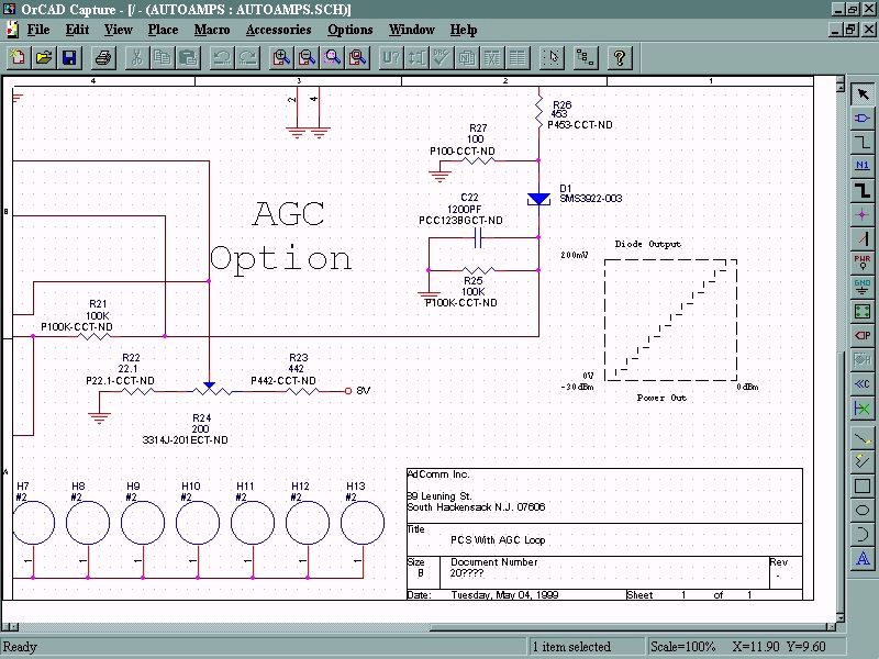
REVISION LTR DESCRIPTION DATE APPROVED - RELEASE REVISION -- SHEET 12 AdComm , 89 LEUNING ST. SOUTH HACKENSACK , NJ 07606 TEL. (201) 342-6349 FAX (201) 342-3559TITLE : PCS BI-DIRECTIONAL AMPLIFIER NEXT ASSY: DRN: CP/DOV DATE: 4/8/9 BDA-1819-60(WITH EXTERNAL POWER SOURCE) CHK: DATE: CAGE CODE SIZE PL- 100073 REV: APPD: DATE: 07TU2 A - SHEET 1 OF 1 TOP ASS'Y NO: 100073 APPD: DATE: JOB NO: 9 9
Test Report
Master: ktlPT24RPTR Date: April 19, 1999 KTL Test Report:9R01459 Applicant:Communication Components Inc. 299 Forest Avenue Paramus, NJ 07652 Equipment Under Test:PCS Bi-Directional Amplifier (E.U.T.) FCC ID:NT3BDA-1819-60 In Accordance With:FCC Part 24, Subpart E Broadband PCS Repeaters Tested By:KTL Ottawa Inc. 3325 River Road, R.R. 5 Ottawa, Ontario K1V 1H2 Authorized By: R. Grant, RF Engineer Date: Total Number of Pages:149 KTL Ottawa FCC PART 24, SUBPART E BROADBAND PCS REPEATERS PROJECT NO.: 9R01459 EQUIPMENT: PCS Bi-Directional Amplifier FCC ID: NT3BDA-1819-60 Page 2 of 139 Table of Contents Section 1. Summary of Test Results General Summary of Test Data Section 2. General Equipment Specification Specifications Description of Modifications for Class II Permissive Change Modifications Made During Testing Theory of Operation System Diagram Section 3. RF Power Output Test Results Measurement Data Power Over Bandwidth Graphs Section 4. Occupied Bandwidth Occupied Bandwidth (CDMA) Test Results CDMA Input and Output Graphs Occupied Bandwidth (GSM) Test Results GSM Input and Output Graphs Occupied Bandwidth (NADC) Test Results NADC Input and Output Graphs Section 5. Spurious Emissions at Antenna Terminals Test Results Test Data Graphs Section 6. Field Strength of Spurious Test Results Test Data Test Data - Radiated Emissions - Uplink Test Data - Radiated Emissions - Downlink Photographs of Test Setup Pre-Scan Data KTL Ottawa FCC PART 24, SUBPART E BROADBAND PCS REPEATERS PROJECT NO.: 9R01459 EQUIPMENT: PCS Bi-Directional Amplifier FCC ID: NT3BDA-1819-60 Page 3 of 139 Table of Contents, continued Section 7. Frequency Stability Test Results Measurement Data Graphs Section 8. Test Equipment List Annex A - Test Methodologies RF Power Output Occupied Bandwidth (CDMA) Occupied Bandwidth (GSM) Occupied Bandwidth (NADC) Spurious Emission at Antenna Terminals Field Strength of Spurious Frequency Stability Annex B - Test Diagrams R.F. Power Output Occupied Bandwidth Spurious Emissions at Antenna Terminals Field Strength of Spurious Frequency Stability KTL Ottawa FCC PART 24, SUBPART E BROADBAND PCS REPEATERS PROJECT NO.: 9R01459 EQUIPMENT: PCS Bi-Directional Amplifier FCC ID: NT3BDA-1819-60 Page 4 of 139 Section 1.Summary of Test Results Manufacturer:Communication Components Inc. Model No.:BDA-1819-60 Serial No.:2380 General: All measurements are traceable to national standards. These tests were conducted on a sample of the equipment for the purpose of demonstrating compliance with FCC Part 24, Subpart E. New SubmissionProduction Unit Class II Permissive ChangePre-Production Unit AMP Equipment Code THIS TEST REPORT RELATES ONLY TO THE ITEM(S) TESTED. THE FOLLOWING DEVIATIONS FROM, ADDITIONS TO, OR EXCLUSIONS FROM THE TEST SPECIFICATIONS HAVE BEEN MADE. See “ Summary of Test Data”. NVLAP LAB CODE: 100351-0 TESTED BY: _____________________________________ DATE: ___________________ Kevin Carr, Technologist KTL Ottawa Inc. authorizes the above named company to reproduce this report provided it is reproduced in its entirety and for use by the company’s employees only. Any use which a third party makes of this report, or any reliance on or decisions to be made based on it, are the responsibility of such third parties. KTL Ottawa Inc. accepts no responsibility for damages, if any, suffered by any third party as a result of decisions made or actions based on this report. This report applies only to the items tested. KTL Ottawa FCC PART 24, SUBPART E BROADBAND PCS REPEATERS PROJECT NO.: 9R01459 EQUIPMENT: PCS Bi-Directional Amplifier FCC ID: NT3BDA-1819-60 Page 5 of 139 Summary Of Test Data NAME OF TESTPARA. NO.SPEC.MEAS.RESULT RF Power Output24.232100WPlotComplies Occupied Bandwidth (CDMA)24.238Input/OutputPlotComplies Occupied Bandwidth (GSM)24.238Input/OutputPlotComplies Occupied Bandwidth (NADC)24.238Input/OutputPlotComplies Spurious Emissions at Antenna Terminals 24.238(a)-13 dBm-13.0 dBmComplies Field Strength of Spurious Emissions24.238(a)-13 dBm E.I.R.P. ChartComplies Frequency Stability24.235N/AN/AN/A Footnotes For N/A’s: Test Conditions: Indoor Temperature: 25 °C Humidity:23 % Outdoor Temperature: 20 °C Humidity:23 % KTL Ottawa FCC PART 24, SUBPART E BROADBAND PCS REPEATERS PROJECT NO.: 9R01459 EQUIPMENT: PCS Bi-Directional Amplifier FCC ID: NT3BDA-1819-60 Page 6 of 139 Section 2.General Equipment Specification Supply Voltage Input: 15 Vdc, via 120 VAC, 60 Hz to 15 Vdc Power Cube Frequency Range:Downlink: A/D Block:1930 MHz to 1949.95 MHz B Block:1950 MHz to 1964.95 MHz Frequency Range:Uplink: A/D Block:1850 MHz to 1869.95 MHz B Block:1870MHz to 1884.95 MHz 20 dB Bandwidth: Type of Modulation and CDMAGSMTDMA Designator: (F9W)(GXW)(DXW) AGC Threshold: Not Applicable Output Impedance: 50 ohm Gain: 66.0 dB Nominal Max Input Power: -35.7 dBm Uplink (dBm)Downlink (dBm) RF Output (Rated):Single: 20.020.0 Composite: 23.023.0 Frequency Translation: F1-F1F1-F2N/A Band Selection: SoftwareDuplexer Change Fullband Coverage KTL Ottawa FCC PART 24, SUBPART E BROADBAND PCS REPEATERS PROJECT NO.: 9R01459 EQUIPMENT: PCS Bi-Directional Amplifier FCC ID: NT3BDA-1819-60 Page 7 of 139 Description of Modifications For Class II Permissive Change KTL Ottawa FCC PART 24, SUBPART E BROADBAND PCS REPEATERS PROJECT NO.: 9R01459 EQUIPMENT: PCS Bi-Directional Amplifier FCC ID: NT3BDA-1819-60 Page 8 of 139 Modifications Made During Testing KTL Ottawa FCC PART 24, SUBPART E BROADBAND PCS REPEATERS PROJECT NO.: 9R01459 EQUIPMENT: PCS Bi-Directional Amplifier FCC ID: NT3BDA-1819-60 Page 9 of 139 Theory of Operation Communication Components Inc. Bi-Directional Amplifier (BDA) improves the sensitivity of base stations in indoor locations where there is a significant amount of cable loss in RF distribution systems as well as weak penetration of the signal from outside of the building. The BDA was specifically designed for low system group delay to minimize Bit Error Rate (BER) of digital transmissions. The BDA block consists of a sin…
Text truncated - open the document above for the full version.
Contact Information
Applicant
Dennis Nathan(President)
Technical Contact
Non-Technical Contact
KTL OTTAWARUBY C DULMAGE
[email protected]1-800-563-6336
Test Firm
Nemko Canada Inc.Stuart Beck
Technical Specifications
| # | Rule Parts | Frequency Range | Power Output | Emission | Tolerance |
|---|---|---|---|---|---|
| 6 | 24E | 1.85 GHz - 1.89 GHz | 320.00 mW | DXW | % |
Other Applications from Communication Components Inc
NT3SERRFU8W
Mar 09, 2020SiriusXM SDAR Fiber Repeater
Equipment Class
BOS - All other signal boosters other than 20.21/90.219
NT3SCB8501WA
Jun 24, 2014Amplifier
Equipment Class
AMP - Amplifier
NT3MCPA2100125
Apr 19, 2011HIGH EFFICIENCY MCPA
Equipment Class
AMP - Amplifier
NT3DAB1819125G2
Jul 28, 2010PCS GSM/EDGE 125W Dual Amplifier Booster
Equipment Class
AMP - Amplifier
NT3CE-1819-10G2
Jul 03, 2007PCS Multi-Channel Cell Extender
Equipment Class
AMP - Amplifier