NT3CE-1819-10G2PCS Multi-Channel Cell Extender
Communication Components Inc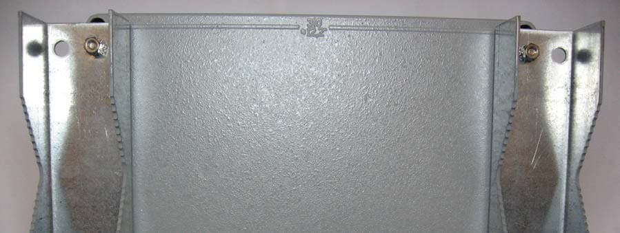
Click to zoom
Application Details
- Equipment Class
- AMP - Amplifier
- Date of Grant
- Jul 03, 2007
- Application Purpose
- Original Equipment
- Date of Application
- Jul 03, 2007
- Equipment Note
- PCS Multi-Channel Cell Extender
- Frequency Range
- 1930.00000000 - 1990.00000000
- Company
- Communication Components Inc
- Country
- United States
Documents & Files
Document Text
Text extracted from the exhibit documents filed with the FCC. Open a document above to read the original.
Users Manual
100141-INST Cell Extender Model CE-1819-10G2 Page 1 of 5 Rev. - 05/2007 User Manual and Installation Instructions CELL EXTENDER CE-1819-10G2 USER MANUAL AND INSTALLATION INSTRUCTIONS INSTALLATION OPTIONS CCI’s Cell Extender product family is easy to install, requires no maintenance, and is fully compatible with the Original Equipment Manufacturer’s (OEM) Base Station equipment. The Cell Extender offers the maximum installation flexibility by allowing the BTS to be physically distanced from the antenna and mounting structure. As such, the need to run both a T1 connection and an AC connection on the mounting structure is eliminated. Three installation options are available: • Configuration 1 - The CE-1819-10G2 can be mounted on the same mounting structure next to the Micro Base Station. This option is ideal when an existing micro-BTS site is being upgraded with a Cell Extender or when both AC and T1 connections are available on the mounting structure. • Configuration 2 - The BTS equipment is installed at ground level (or indoors) and the Cell Extender is mounted on the mounting structure, in close proximity to the antenna. This configuration is ideal for environments where AC lines and T1-connections are not easily available on the mounting structure or when it is desired to keep the BTS equipment at ground level. For this configuration, the Cell Extender should be ordered with the Remote Power Option (Option 3) which includes a Bias-T and Remote Power Supply module to provide DC power to the Cell Extender over the Coax cable. • Configuration 3 - Both the BTS and the Cell Extender equipment are installed at the ground level or indoors. This is intended for applications where it is impractical to install any equipment other than the antenna on the mounting structure. MOUNTING INSTRUCTIONS The CE-1819-10G2 can be either pole mounted or wall mounted. It is delivered with a Pole Mounting Kit to allow it to be secured to a pole structure. A separate document titled Mounting Instructions – Outdoor Cell Extender (100141-MNT) is included which provides detailed mounting instructions. COMMUNICATION COMPONENTS INC Extending Wireless Coverage 89 Leuning Street Phone: 201-342-3338 2 nd Floor Fax: 201-342-3339 South Hackensack, NJ 07606 www.cciproducts.com 100141-INST Cell Extender Model CE-1819-10G2 Page 2 of 5 Rev. - 05/2007 User Manual and Installation Instructions Diagram 1 – Side view of Cell Extender with Pole Mounting Brackets Installed CONNECTING THE CELL EXTENDER TO THE BTS EQUIPMENT The Cell Extender sits between the BTS equipment and the Antennas. The 7/16” DIN connector labeled “FEEDER A (TX/RX)” is connected via a coax feeder line to the TX/RX output of the BTS. The connector labeled “Antenna A (TX/RX)” is then connected to the actual Antenna. For BTS equipment with receive diversity and Cell Extenders with Option 1 – Receive Diversity, the 7/16” DIN connector labeled “FEEDER B (Rx only)” is connected to the “RX” input of the BTS equipment. Likewise, the connector labeled “ANTENNA B (Rx only)” is then connected to the diversity Antenna. POWERING THE CELL EXTENDER The Cell Extender can be ordered with three separate power options: Direct AC (default), Remote Power (Option 3), or Direct DC power (Option 5/6). With Direct AC, the Cell Extender is supplied with a power cord that is plugged into a 110VAC or 220VAC power source. With the Remote Power option, a remote power module (see Diagram 2) supplies the necessary voltage to the Cell Extender over the coax cable. The Direct DC power option is for applications where a solar power source or battery voltage is being used to power the unit. Two direct DC voltages are supported: 24-30VDC and 36- 72VDC. With the Direct AC and Direct DC options, the Cell Extender is provided with a hermetically sealed connector and a power cable that contains three wires – black, white and green. The pinouts are defined below: AC/DC Input cable Wire Color Pin # Direct AC Direct 24VDC Direct 48VDC Black PIN C Line (hot) No Connection No Connection White PIN A Neutral +24-30 VDC +36-72VDC Green PIN B Chassis Ground DC Return DC Return 100141-INST Cell Extender Model CE-1819-10G2 Page 3 of 5 Rev. - 05/2007 User Manual and Installation Instructions CONNECTING THE ALARMS The Cell Extender provides a dry relay contact for alarming purposes. Both the normally open and the normally closed states are provided. A separate hermetically-sealed Alarm connector is provided with wires as specified below: Wire Color Pin # Function * Black PIN D Common White or Yellow PIN B Normally Closed Red PIN A Normally Open Green PIN C Not Used * When unit is operational The dry relay alarm is activated in the following conditions: Alarm Trigger Conditions LNA 1 Failure Loss of Gain > 3 dB LNA 2 Failure Loss of Gain > 3 dB PA 1 Failure Full Loss of Gain PA 2 Failure Full Loss of Gain Power Supply Failure DC voltage < +6VDC SETTING UP THE BTS MAXIMUM TX POWER The gain on the CE-1819-10G2 is fixed at the factory. No internal gain adjustments can be made in the field. The user must verify that the composite input RF power to the Cell Extender does not exceed the absolute maximum input level (+32.05dBm) in order for the RF output spectral emissions to be compliant with the FCC spurious emissions limit of -13dBm outside of the assigned frequency block. The maximum rated composite output RF power for this device is +43dBm. This equipment complies with Part 24 of the FCC rules. Any changes or modifications not expressly approved by the manufacturer could void the user’s authority to operate the equipment. In order to comply with FCC rules for RF exposure, it must be observed that the antenna connected to this equipment be fixed on an outdoor structure and that it must have a minimum separation distance of 3 meters between it and any person. In accordance with RSS-131, the manufacturer’s rated output power for this equipment is for single carrier operation. For situations when multiple carriers are p…
Text truncated - open the document above for the full version.
Cover Letter(s)
June 21, 2007 Federal Communications Commission Authorization & Evaluation Division 7435 Oakland Mills Road Columbia, MD 21046 Re: Request for Confidentiality In reference to the application under FCC ID: NT3CE-1819-10G2, and pursuant to Sections 0.457(d)(1)(ii) and 0.459 of the Commission’s Rules, Communication Components Inc. hereby requests confidential treatment of the accompanying information as outlined below: (1) Schematic Diagrams contained in electronic file identified as CE-1819- 10G2_schem.PDF. (2) Parts lists contained in electronic file identified as CE-1819-10G2_parts.PDF. (3) Internal Photographs contained in the electronic file identified as CE-1819- 10G2_internal.pdf. (4) Operational description contained in the electronic file identified as CE-1819- 10G2_operational.pdf (5) Block diagram identified as CE-1819-10G2 Block Diagram.doc The above materials contain trade secrets and proprietary information not customarily released to the public. The public disclosure of these materials might be harmful to the Applicant and provide unjustified benefits to its competitors. Specifically, disclosure of the internal photographs will reveal proprietary circuit optimization techniques which currently give us a significant advantage over our competition. This PCS amplifier is also installed in an area which is not readily accessible to the public and is strictly maintained by factory trained personnel only. Communication Components understands that pursuant to Rule 0.457(d)(1)(ii), disclosure of this Application and all accompanying documents will not be made prior to the date of the Grant for this application. Sincerely, Dennis Nathan President Communication Components Inc. Communication Components, Inc. Phone: 201-342-3338 89 Leuning Street Fax: 201-342-3339 South Hackensack, NJ 07606 www.cciproducts.com
Cover Letter(s)
Federal Communications Commission 7435 Oakland Mills Road Columbia, MD 21046 USA Authority to Act as Agent to the Federal Communications Commission On our behalf, I appoint Nemko Dallas, Inc. to act as agent in the preparation of this application for equipment authorization to the Federal Communications Commission. I certify that submitted Exhibits properly describe the device or system for which equipment authorization is sought. I also certify that each unit manufactured, imported or marketed, as defined in the Commission's regulations will have affixed to it a label identical to that submitted for approval with this application. APPLICANT ANTI-DRUG ABUSE CERTIFICATION: In signing this letter, Applicant certifies that, in the case of an individual applicant, he or she is not subject to a denial of federal benefits, that includes FCC benefits, pursuant to Section 5301 of the Anti-Drug Abuse Act of 1988, 21 U.S.C. 853(a), or, in the case of a non- individual applicant (e.g. corporation, partnership or other unincorporated association), no party to the application is subject to a denial of federal benefits, that includes FCC benefits, pursuant to that section. For the definition of a "party" for these purposes, see 47 CFR 1.2002(b). Dated this 21 st Day of May 2007 Agency agreement expiration date: 31 st Day of December 2007 By: Dennis Nathan Title: President Telephone: (201) 342-3338 Applicant: Communication Components Inc. Communication Components, Inc. 89 Leuning Street Phone: 201-342-3338 South Hackensack, NJ 07606 Fax: 201-342-3339 www.cciproducts.com
External Photos
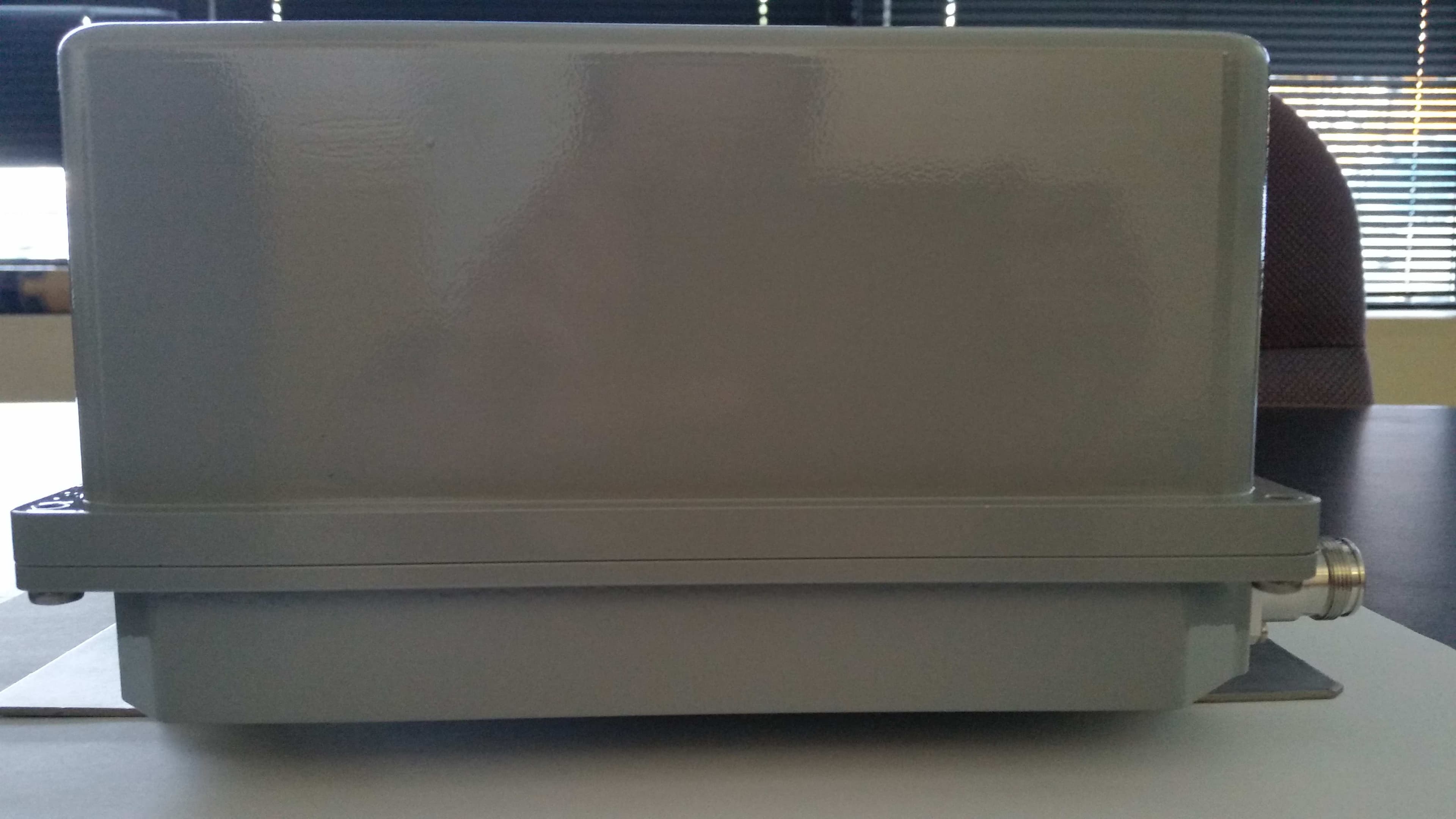
CELL EXTENDER CE-1819-10G2 External Photos CE-1819-10G2 Top View COMMUNICATION COMPONENTS INC Extending Wireless Coverage 89 Leuning Street Phone: 201-342-3338 2 nd Floor Fax: 201-342-3339 South Hackensack, NJ 07606 www.cciproducts.com CE-1819-10G2 Bottom View CE-1819-10G2 Front View CE-1819-10G2 Rear View with Pole Mount Brackets CE-1819-10G2 Left Side View CE-1819-10G2 Right Side View
ID Label/Location Info
CELL EXTENDER CE-1819-10G2 Label COMMUNICATION COMPONENTS INC Extending Wireless Coverage 89 Leuning Street Phone: 201-342-3338 2 nd Floor Fax: 201-342-3339 South Hackensack, NJ 07606 www.cciproducts.com
ID Label/Location Info
CELL EXTENDER CE-1819-10G2 Label Location COMMUNICATION COMPONENTS INC Extending Wireless Coverage 89 Leuning Street Phone: 201-342-3338 2 nd Floor Fax: 201-342-3339 South Hackensack, NJ 07606 www.cciproducts.com
Parts List/Tune Up Info
Tuning Procedure The CE-1819-10G2 PCS Cell Enhancer has no internal field tuning adjustment for the rf signal. All adjustments are performed at the factory. It is the responsibility of the customer to limit the input power to 1.6 Watts when connected to either a GSM/EDGE or CDMA BaseStation transmitter. This adjustment is done by means of a high power attenuator and is performed upon installation of the device by qualified personnel only.
Parts List/Tune Up Info
CELL EXTENDER CE-1819-10G2 DC Voltages and Currents The maximum operational current for this system is : 1.5A @ 110VAC 0.75A @ 220 VAC The DC operational voltage is: +28VDC, ±1VDC COMMUNICATION COMPONENTS INC Extending Wireless Coverage 89 Leuning Street Phone: 201-342-3338 2 nd Floor Fax: 201-342-3339 South Hackensack, NJ 07606 www.cciproducts.com
RF Exposure Info
Prediction of MPE limit at a given distance Equation from page 18 of OET Bulletin 65, Edition 97-01 where:S = power density P = power input to the antenna G = power gain of the antenna in the direction of interest relative to an isotropic radiator R = distance to the center of radiation of the antenna Maximum peak output power at antenna input terminal:43.09(dBm) Maximum peak output power at antenna input terminal:20370.42078(mW) Antenna gain(typical):0(dBi) Maximum antenna gain:1(numeric) Time Averaging:100(%) Prediction distance:300(cm) Prediction frequency:1960(MHz) MPE limit for uncontrolled exposure at prediction frequency:1(mW/cm^2) Power density at prediction frequency:0.018011(mW/cm^2) Margin of compliance:-17.4(dB) 2 4R PG S π =
Test Report
Nemko Test Report: 4287RUS1 Applicant: Communication Components 89 Leuning Street 2 nd Floor South Hackensack, NJ 07606 USA Equipment Under Test: CE-1819-10G2 (E.U.T.) In Accordance With: CFR 47, Part 24, Subpart E Broadband PCS Repeaters Tested By: Nemko USA, Inc. 802 N. Kealy Lewisville, TX 75057-3136 TESTED BY: DATE: 01 May 2007 David Light, Senior Wireless Engineer APPROVED BY: DATE: 2 nd May 2007 Number of Pages: 36 Nemko USA, Inc. CFR 47, PART 24, SUBPART E BROADBAND PCS REPEATERS EQUIPMENT: CE-1819-10 G2 REPORT NO.: 4287RUS1 Page 2 of 36 Table of Contents SECTION 1. SUMMARY OF TEST RESULTS 3 SECTION 2. GENERAL EQUIPMENT SPECIFICATION 5 SECTION 3. RF POWER OUTPUT 7 SECTION 4. OCCUPIED BANDWIDTH 8 SECTION 5. SPURIOUS EMISSIONS AT ANTENNA TERMINALS 15 SECTION 6. FIELD STRENGTH OF SPURIOUS 25 SECTION 7. TEST EQUIPMENT LIST 26 ANNEX A - TEST DETAILS 27 ANNEX B - TEST DIAGRAMS 33 Nemko USA, Inc. CFR 47, PART 24, SUBPART E BROADBAND PCS REPEATERS EQUIPMENT: CE-1819-10 G2 REPORT NO.: 4287RUS1 Section 1. Summary of Test Results Manufacturer Communication Components Model No.: CE-1819-10G2 Serial No.: 031016 (Lower Band) and 031026 (Upper Band) General: All measurements are traceable to national standards. These tests were conducted on a sample of the equipment for the purpose of demonstrating compliance with CFR 47, Part 24, Subpart E. New Submission Production Unit Class II Permissive Change Pre-Production Unit THIS TEST REPORT RELATES ONLY TO THE ITEM(S) TESTED. THE FOLLOWING DEVIATIONS FROM, ADDITIONS TO, OR EXCLUSIONS FROM THE TEST SPECIFICATIONS HAVE BEEN MADE. See “ Summary of Test Data”. Nemko USA Inc. authorizes the above named company to reproduce this report provided it is reproduced in its entirety and for use by the company’s employees only. Any use which a third party makes of this report, or any reliance on or decisions to be made based on it, are the responsibility of such third parties. Nemko USA Inc. accepts no responsibility for damages, if any, suffered by any third party as a result of decisions made or actions based on this report. This report applies only to the items tested. Page 3 of 36 Nemko USA, Inc. CFR 47, PART 24, SUBPART E BROADBAND PCS REPEATERS EQUIPMENT: CE-1819-10 G2 REPORT NO.: 4287RUS1 Page 4 of 36 Summary Of Test Data NAME OF TEST PARA. NO. SPEC. RESULT RF Power Output 24.232 100W Complies Occupied Bandwidth 2.1049 Input/Output Complies Spurious Emissions at Antenna Terminals 24.238(a) -13 dBm Complies Field Strength of Spurious Emissions 24.238(a) -13 dBm E.I.R.P. Complies Frequency Stability 24.235 NA Footnotes: (1) Modulation characteristics were not tested since the E.U.T. processes but does not produce a modulated waveform. (2) Frequency stability was not tested since the E.U.T has no frequency conversion capabilities. Nemko USA, Inc. CFR 47, PART 24, SUBPART E BROADBAND PCS REPEATERS EQUIPMENT: CE-1819-10 G2 REPORT NO.: 4287RUS1 Page 5 of 36 Section 2. General Equipment Specification Supply Voltage Input: 120 Vac Frequency Bands: Downlink: Block A : 1930 – 1945 MHz Block D : 1945 – 1950 MHz Block B : 1950 – 1965 MHz Block E : 1965 – 1970 MHz Block F : 1970 – 1975 MHz Block C : 1975 – 1990 MHz Frequency Bands: Uplink: Block A : 1850 – 1865 MHz Block B : 1865 – 1870 MHz Block C : 1870 – 1885 MHz Block D : 1885 – 1890 MHz Block E : 1890 – 1895 MHz Block F : 1895 – 1910 MHz CDMA GSM NADC W-CDMA EDGE (F9W) (GXW) (DXW) (F9W) (G7W) Type of Modulation and Designator: System Gain: 10 dB Output Impedance: 50 ohms NAW RF Output (Rated): Uplink NAdBm 20W RF Output (Rated): Downlink 43dBm F1-F1 F1-F2 N/A Frequency Translation: Software Duplexer Fullband Band Selection: Nemko USA, Inc. CFR 47, PART 24, SUBPART E BROADBAND PCS REPEATERS EQUIPMENT: CE-1819-10 G2 REPORT NO.: 4287RUS1 Page 6 of 36 Description of EUT The device is a booster amplifier for use in the PCS band. The device works in either a GSM, EDGE or CDMA network. System Diagram Pleas refer to separate exhibit. Nemko USA, Inc. CFR 47, PART 24, SUBPART E BROADBAND PCS REPEATERS EQUIPMENT: CE-1819-10 G2 REPORT NO.: 4287RUS1 Page 7 of 36 Section 3. RF Power Output NAME OF TEST: RF Power Output PARA. NO.: 24.232 TESTED BY: David Light DATE: 01 May 2007 Test Results: Complies. Measurement Data: Direction Modulation Power (dBm) Power (W) Uplink CDMA NA NA Downlink CDMA 43.07 20.28 Uplink EDGE NA NA Downlink EDGE 43.09 20.37 Uplink GSM NA NA Downlink GSM 43.09 20.37 Equipment Used: 1053-1036-1529-1604-1064 Measurement Uncertainty: +/- 1.7dB Temperature: 20 °C Relative Humidity: 48 % Nemko USA, Inc. CFR 47, PART 24, SUBPART E BROADBAND PCS REPEATERS EQUIPMENT: CE-1819-10 G2 REPORT NO.: 4287RUS1 Page 8 of 36 Section 4. Occupied Bandwidth NAME OF TEST: Occupied Bandwidth PARA. NO.: 24.238 TESTED BY: David Light DATE: 01 May 2007 Test Results: Complies. Test Data: See attached plot(s). Equipment Used: 1053-1036-1529-1604-1064 Measurement Uncertainty: 1X10 -7 ppm Temperature: 20 °C Relative Humidity: 48 % Nemko USA, Inc. CFR 47, PART 24, SUBPART E BROADBAND PCS REPEATERS EQUIPMENT: CE-1819-10 G2 REPORT NO.: 4287RUS1 Test Data – Occupied Bandwidth CDMA - Output Page 9 of 36 Nemko USA, Inc. CFR 47, PART 24, SUBPART E BROADBAND PCS REPEATERS EQUIPMENT: CE-1819-10 G2 REPORT NO.: 4287RUS1 Test Data – Occupied Bandwidth CDMA - Input Page 10 of 36 Nemko USA, Inc. CFR 47, PART 24, SUBPART E BROADBAND PCS REPEATERS EQUIPMENT: CE-1819-10 G2 REPORT NO.: 4287RUS1 Test Data – Occupied Bandwidth EDGE - Output Page 11 of 36 Nemko USA, Inc. CFR 47, PART 24, SUBPART E BROADBAND PCS REPEATERS EQUIPMENT: CE-1819-10 G2 REPORT NO.: 4287RUS1 Test Data – Occupied Bandwidth EDGE - Input Page 12 of 36 Nemko USA, Inc. CFR 47, PART 24, SUBPART E BROADBAND PCS REPEATERS EQUIPMENT: CE-1819-10 G2 REPORT NO.: 4287RUS1 Test Data – Occupied Bandwidth GSM - Output Page 13 of 36 Nemko USA, Inc. CFR 47, PART 24, SUBPART E BROADBAND PCS REPEATERS EQUIPMENT: CE-1819-10 G2 REPORT NO.: 4287RUS1 Test Data – Occupied Bandwidth GSM - Input Page 14 of 36 …
Text truncated - open the document above for the full version.
Contact Information
Applicant
Dennis Nathan(President)
Technical Contact
Non-Technical Contact
Nemko USA IncHarry Ward
[email protected]972 436 9600
Test Firm
Nemko USA, Inc.Tom Tidwell
Technical Specifications
| # | Rule Parts | Frequency Range | Power Output | Emission | Tolerance |
|---|---|---|---|---|---|
| 3 | 24E | 1.93 GHz - 1.99 GHz | 20 W | G7W | Amp |
Other Applications from Communication Components Inc
NT3SERRFU8W
Mar 09, 2020SiriusXM SDAR Fiber Repeater
Equipment Class
BOS - All other signal boosters other than 20.21/90.219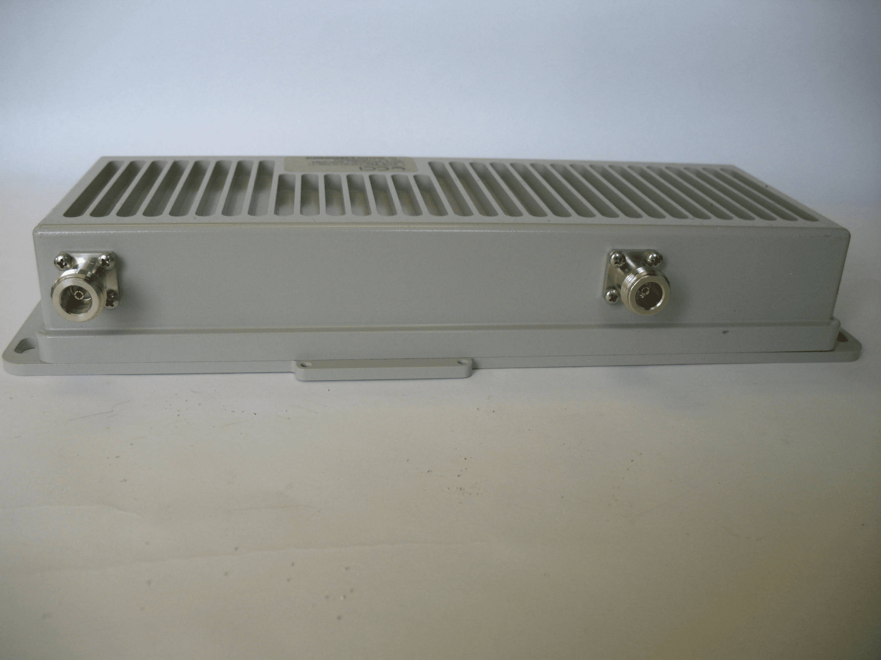
NT3SCB8501WA
Jun 24, 2014Amplifier
Equipment Class
AMP - Amplifier
NT3MCPA2100125
Apr 19, 2011HIGH EFFICIENCY MCPA
Equipment Class
AMP - Amplifier
NT3DAB1819125G2
Jul 28, 2010PCS GSM/EDGE 125W Dual Amplifier Booster
Equipment Class
AMP - Amplifier
NT3CE-1819-125MC
May 07, 2007PCS Band Multi Carrier Cell Extender
Equipment Class
AMP - Amplifier