NT3BDA-8087-52CBi-Directional Amplifier model BDA-8087-52C
Communication Components Inc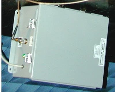
Click to zoom
Application Details
- Equipment Class
- AMP - Amplifier
- Date of Grant
- Jan 15, 2001
- Application Purpose
- Original Equipment
- Date of Application
- Jan 15, 2001
- Equipment Note
- Bi-Directional Amplifier model BDA-8087-52C
- Frequency Range
- 869.00000000 - 894.00000000
- Company
- Communication Components Inc
- Country
- United States
Documents & Files
Document Text
Text extracted from the exhibit documents filed with the FCC. Open a document above to read the original.
Users Manual
BDA TEST AND INSTALLATION PROCEDURE 1. INSPECTION CAUTION: A minimum separation distance of 20 centimeters between the transmit antenna and nearby persons must be maintained. If this separation distance is not maintained, the device may not be in compliance with FCC RF Exposure rules. Open the enclosure of the bi-directional amplifier (BDA) and carefully inspect the inside assembly of the unit. Verify that all components are properly secured to the base of enclosure, there are no loose parts, and all interconnections are reliable. Carefully close the enclosure. Unpack the outdoor and indoor antennas and inspect the content. Verify that there are no loose parts or rattling in the antennas. Make sure that antennas are not deformed. 2. SITE INSTALLATION 2.1 "Donor" (outdoor) Antenna Installation On the roof of the building chose the location of the "donor" Yagi antenna. Point the antenna towards the "donor" site. Connect the mobile phone or spectrum analyzer to the antenna using short cable with type "N" connector on the antenna side and proper adapter on the test equipment side. Adjust the position of the antenna for the maximum reading. The average power level should not be below -85 dBm. Record the measured data. Install the antenna following instructions of the antenna manufacturer. CAUTION: A minimum separation distance of 20 centimeters between the transmit antenna and nearby persons must be maintained. If this separation distance is not maintained, the devicemay not be in compliance with FCC RF Exposure rules. CAUTION Use caution working with the bi-directional amplifier. Disconnect the 115 VAC from the amplifier prior to inspection. 2.2 Surge Protector Installation Connect the cable run to the antenna and pass it through the roof manifold. Inside of the building find a location for the surge protector near the construction ground where it can be reliably grounded. Install the surge protector and connect the cables to both sides. Bring the cable run to the BDA location. Using a spectrum analyzer or mobile phone, measure the signal from the "donor" site. It has to be from 1 dB to 3 dB below the antenna output level. Exact loss depends on the cable type and length of the cable. 2.3 Indoor Antenna (s) Installation. From preliminary evaluation of the blueprints of the service area, the approximate locations of the indoor antennas must be established. The level of the signal at the boundary of the service area can be a guideline for the location of the antennas. Several parameters must be considered: a) the gain of the Omni antenna is 0 dBd. b) the free space propagation loss is approximately -60 dB per 100 ft. c) the acceptable level at the lowest signal position for the mobile is -80 dBm. Following the installation instructions mount antennas at the ceiling tiles or any other appropriate locations. Run the cables from antennas to the BDA location. Use power combiner, if needed, to interconnect the antenna cables. CAUTION: A minimum separation distance of 20 centimeters between the transmit antenna and nearby persons must be maintained. If this separation distance is not maintained, the device may not be in compliance with FCC RF Exposure rules. 2.4 BDA Installation The bi-directional amplifier can be installed as a freestanding unit lying on the shelf of the cabinet or any other adequately strong support. It can also be secured by screws to the wall or rack using four holes in the tabs located at the back plate of the enclosure. AC power must be available in the vicinity of the BDA. It is recommended that the environmental temperature will not exceed 65 C and the area will be adequately ventilated. Once amplifier is installed in place, open the front door and verify that all internal parts are securely mounted. Connect the ground wire to the ground stud on the enclosure. Plug in the AC cable into the AC socket. The green light on the enclosure must be lit on. a) Downlink Gain Setting. Connect the cable from the lightning protector and “DONOR” antenna to the “DONOR” port of the BDA. Connect a power meter or spectrum analyzer to the "SERVICE" port (Uplink input connector) of the BDA. Measure the power of the signal at the “SERVICE” port of the BDA. It should not exceed +24.8 dBm for a single channel or +19.5 dBm for three channels of CDMA system application. It should not exceed +25 dBm for single channel or +19.3 dBm for three channels of TDMA system application. These power levels will guarantee the intermodulation products below -13 dBm, which is in compliance with FCC regulation. After the output power level is set correctly, connect the donor antenna cable to the "DONOR" port of the BDA. b) Uplink Gain Setting. Connect the indoor (service area) antenna cable to the "SERVICE" port of the BDA. Initiate the call from the closest position of the mobile to the service area antenna. Observe the yellow "Uplink AGC ON" light on BDA enclosure. The threshold of the AGC in the uplink amplifier is factory preset at the gain that corresponds to the intermodulation products level of -13 dBm. If the signal level is low and AGC light is not "ON", slowly increase the gain of the downlink amplifier until the light will be lit. Back off the potentiometer just below the level when the light is off. Check the security of the installation and presence of the AC power. Amplifier is ready for operation. 3. REMOVE BI-DIRECTIONAL AMPLIFIER 3.1 Unplug the AC cord from the socket. AC light on the amplifier must be off. Disconnect all coaxial cables. 3.2 Dismount amplifier from the wall or remove it from the shelf. 4. SHIPMENT AND STORAGE OF THE BDA 4.1 Use common technical shop practices to ensure equipment protection during shipment or storage. 5. TROUBLESHOOTING AND FAULT DETECTION 5.1 Check the presence of the AC power. The AC light must be on. 5.2 Check the continuity of all connecting cables. WARNING! 110 VAC CAN BE LETHAL! ALWAYS UNPLUG THE AMPLIFIER BEFORE SERVICING THE INTERIOR. . 5.3 If the fault was n…
Text truncated - open the document above for the full version.
Cover Letter(s)
schem1_fcc.jpg and schem2_fcc.jpg.
ID Label/Location Info
FCC ID: NT3BDA-8087-52C EQUIPMENT LABEL 1.5” 0.75 Communication Components, Inc. MODEL NO: BDA-8087-52C FCC ID: NT3BDA-8087-52C This drawing represents the label that will be affixed to the front of the amplifier case. This label will be printed on a mylar material which has been selected to last the life of the product. 10” 12” Front view of cabinet.
Internal Photos
Photo 1 - AGC Amplifier Photo 2 - AGC Amplifier Photo 3 - AGC Amplifier Photo 4 - MGC Amplifier Photo 5 - MGC Amplifier Photo 6 - MGC Amplifier
Operational Description
KTL Dallas FCC PART 22, SUBPART H CELLULAR BAND REPEATERS EQUIPMENT:BDA-8087-52PROJECT NO.:0L0265RUS2 Page 6 of 50 Description of Operation The BDA is a Bi-directional amplifier. It is designed to exchange radio communications in buildings, basements, tunnels, and other RF shielded environments. It improves the sensitivity of base stations in indoor locations where there is a significant amount of cable loss in RF distribution systems. It contains two amplifiers providing amplification of RF signals in Uplink and Downlink frequency bands. They are connected to the external cables via frequency selective duplexers in order to attenuate all signals that are not in the designated bands. KTL Dallas FCC PART 22, SUBPART H CELLULAR BAND REPEATERS EQUIPMENT:BDA-8087-52PROJECT NO.:0L0265RUS2 Page 7 of 50 System Diagram POWER SUPPLY AGC MGC MGC UPLINK DOWNLINK FUNCTIONAL BLOCK DIAGRAM P/N: BDA-8087-52 851-866 MHz (BASE-TO-MOBILE) 806-821 MHz (MOBILE-TO-BASE) 851-866 MHz 806-821 MHz DONOR ANTENNA SERVICE AREA DIPLEXER DIPLEXER AMPLIFIER 1 AMPLIFIER 2
Parts List/Tune Up Info
Tune-up info See response to TCB questions exhibit in test report section
RF Exposure Info
MPE PREDICTION FOR NT3BDA-8087-52C Prediction of MPE limit at a given distance Equation from page 18 of OET Bulletin 65, Edition 97-01 where:S = power density P = power input to the antenna G = power gain of the antenna in the direction of interest relative to an isotropic radiator R = distance to the center of radiation of the antenn Maximum peak output power at antenna input terminal:20.00(dBm) Maximum peak output power at antenna input terminal:100(mW) Maximum antenna gain:12(dBi) Maximum antenna gain:15.84893(numeric) Prediction distance:20(cm) Prediction frequency:824(MHz) MPE limit for uncontrolled exposure at prediction frequency:0.549333(mW/cm^2) Power density at prediction frequency:0.315304(mW/cm^2) Maximum allowable antenna gain:14.41106(dBi) 2 4R PG S π =
Test Report
KTL Test Report:0L0265RUS2 Applicant:Communication Components, Inc. 299 Forest Ave. Paramus, NJ 07652 Equipment Under Test:BDA-8087-52 (E.U.T.) In Accordance With:FCC Part 22, Subpart H Cellular Band Repeaters Tested By:KTL Dallas Inc. 802 N. Kealy Lewisville, TX 75057-3136 Authorized By: Tom Tidwell, RF Group Manager Date:12/6/00 Total Number of Pages:50 KTL Dallas FCC PART 22, SUBPART H CELLULAR BAND REPEATERS EQUIPMENT:BDA-8087-52PROJECT NO.:0L0265RUS2 Page 2 of 50 Table of Contents SECTION 1. SUMMARY OF TEST RESULTS...............................................................................................3 SECTION 2. GENERAL EQUIPMENT SPECIFICATION............................................................................5 SECTION 3. RF POWER OUTPUT.................................................................................................................8 SECTION 4. OCCUPIED BANDWIDTH.........................................................................................................9 SECTION 5. SPURIOUS EMISSIONS AT ANTENNA TERMINALS.........................................................10 SECTION 6. FIELD STRENGTH OF SPURIOUS........................................................................................19 SECTION 7. FREQUENCY STABILITY......................................................................................................32 SECTION 8. TEST EQUIPMENT LIST........................................................................................................35 ANNEX A - TEST DETAILS........................................................................................................................36 ANNEX B - TEST DIAGRAMS....................................................................................................................45 KTL Dallas FCC PART 22, SUBPART H CELLULAR BAND REPEATERS EQUIPMENT:BDA-8087-52PROJECT NO.:0L0265RUS2 Page 3 of 50 Section 1.Summary of Test Results Manufacturer:Communication Components, Inc. Model No.:BDA-8087-52 Serial No.:0052 General:All measurements are traceable to national standards. These tests were conducted on a sample of the equipment for the purpose of demonstrating compliance with FCC Part 22, Subpart H. New SubmissionProduction Unit Class II Permissive ChangePre-Production Unit THIS TEST REPORT RELATES ONLY TO THE ITEM(S) TESTED. THE FOLLOWING DEVIATIONS FROM, ADDITIONS TO, OR EXCLUSIONS FROM THE TEST SPECIFICATIONS HAVE BEEN MADE. See “ Summary of Test Data”. NVLAP LAB CODE: 100426-0 KTL Dallas Inc. authorizes the above named company to reproduce this report provided it is reproduced in its entirety and for use by the company’s employees only. Any use which a third party makes of this report, or any reliance on or decisions to be made based on it, are the responsibility of such third parties. KTL Dallas Inc. accepts no responsibility for damages, if any, suffered by any third party as a result of decisions made or actions based on this report. This report applies only to the items tested. KTL Dallas FCC PART 22, SUBPART H CELLULAR BAND REPEATERS EQUIPMENT:BDA-8087-52PROJECT NO.:0L0265RUS2 Page 4 of 50 Summary Of Test Data NAME OF TESTPARA. NO.SPEC.MEAS.RESULT RF Power Output22.913(a)500W ERP.085Complies Occupied Bandwidth (Voice & SAT)22.917(c)MaskN/AN/A Occupies Bandwidth (Wideband Data)22.917(d)MaskN/AN/A Occupied Bandwidth (ST)22.917(d)MaskN/AN/A Occupied Bandwidth (Digital)NoneNoneN/AN/A Spurious Emissions at Antenna Terminals 22.917-13 dBm-13 dBmComplies Field Strength of Spurious Emissions22.917 -13 dBm E.I.R.P. -23.4 dBmComplies Frequency Stability22.3551.5 ppmN/AN/A (1) Since the E.U.T. does not contain modulation circuitry modulation testing was not performed. (2) Sice the E.U.T. only amplifies the signal it receives, Frequency Stability was not tested. . KTL Dallas FCC PART 22, SUBPART H CELLULAR BAND REPEATERS EQUIPMENT:BDA-8087-52PROJECT NO.:0L0265RUS2 Page 5 of 50 Section 2.General Equipment Specification Supply Voltage Input: 115 VAC Frequency Range:Downlink: 869 – 894 MHz Frequency Range:Uplink: 824 – 849 MHz CDMAGSMNADCCDPDAMPS (F9W)(GXW)(DXW)(F9W)(F8W, F1D) Type of Modulation and Designator: Output Impedance: 50 ohms Downlink: Multi-channel:.100W RF Output (Rated): Single Channel:.316W Uplink: Multi-channel:.100W Single Channel:.316W Frequency Translation: F1-F1F1-F2N/A Software Duplexer Change Fullband Coverage Band Selection: KTL Dallas FCC PART 22, SUBPART H CELLULAR BAND REPEATERS EQUIPMENT:BDA-8087-52PROJECT NO.:0L0265RUS2 Page 6 of 50 Description of Operation The BDA is a Bi-directional amplifier. It is designed to exchange radio communications in buildings, basements, tunnels, and other RF shielded environments. It improves the sensitivity of base stations in indoor locations where there is a significant amount of cable loss in RF distribution systems. It contains two amplifiers providing amplification of RF signals in Uplink and Downlink frequency bands. They are connected to the external cables via frequency selective duplexers in order to attenuate all signals that are not in the designated bands. KTL Dallas FCC PART 22, SUBPART H CELLULAR BAND REPEATERS EQUIPMENT:BDA-8087-52PROJECT NO.:0L0265RUS2 Page 7 of 50 System Diagram POWER SUPPLY AGC MGC MGC UPLINK DOWNLINK FUNCTIONAL BLOCK DIAGRAM P/N: BDA-8087-52 851-866 MHz (BASE-TO-MOBILE) 806-821 MHz (MOBILE-TO-BASE) 851-866 MHz 806-821 MHz DONOR ANTENNA SERVICE AREA DIPLEXER DIPLEXER AMPLIFIER 1 AMPLIFIER 2 KTL Dallas FCC PART 22, SUBPART H CELLULAR BAND REPEATERS EQUIPMENT:BDA-8087-52PROJECT NO.:0L0265RUS2 Page 8 of 50 Section 3.RF Power Output NAME OF TEST: RF Power OutputPARA. NO.: 2.1046 TESTED BY: David LightDATE: 10/3/00 Test Results: Complies. Test Data: Modulation Type Single Channel Power Output (dBm) Total Power Output with 3 Carriers (dBm) UplinkCDMA24.019.8 DownlinkCDMA24.819.5 UplinkNADC24.819.3 DownlinkNADC25.019.3 Equipment Used: 406, 1021 Measurement Uncertainty: +/-0.6dB Temperature: 24 °C Relative Hu…
Text truncated - open the document above for the full version.
Test Report
Dallas Headquarters: 802 N. Kealy Lewisville, TX 75057 Tel: (972) 436-9600 Fax: (972) 436-2667 KTL Dallas, Inc. Field Strength of Spurious Emissions Page 1 of1 Complete X Job No.:0L0265RDate:8/15/00Preliminary Specification:CFR 47, Part 2.1053Temperature(°C):22 Tested By:David LightRelative Humidity(%)50 E.U.T.:BDA Configuration:Transmit - Full Power Sample Number:S01 Location:AC 3RBW:1 MHzMeasurement Detector Type:PeakVBW:1 MHz Distance: 3m Test Equipment Used Antenna:993Directional Coupler: Pre-Amp:1016Cable #1:1484 Filter: Cable #2:1485 Receiver:1464Cable #3: Attenuator #1 Cable #4: Attenuator #2: Mixer: Additional equipment used: Measurement Uncertainty: +/-3.6 dB FrequencyMeterCorrectionPre-AmpSubstitutionERPERPPolarityComments ReadingFactorGainAntenna Gain (MHz) (dBm)(dB) (dB) (dBd)(dBm)(mW) 1630-65.032.731.56.4-57.5 0.000002H 2450-64.536.7326.9-53.0 0.000005H 3260-68.835.832.48.1-57.3 0.000002H 4080-67.335.231.37.9-55.50.000003 H 8150-69.042.233.19.7-50.20.000010 H 1630-65.029.931.56.4-60.30.000001 V 2450-64.534.1326.9-55.60.000003 V 3260-68.837.132.48.1-56.00.000003 V 4080-67.342.831.37.9-47.90.000016 V 8150-69.041.633.19.7-50.8 0.000008V 1630-62.532.731.56.4-55.0 0.000003H 2450-65.336.7326.9-53.8 0.000004H 3260-63.535.832.48.1-52.00.000006 H 4080-63.735.231.37.9-51.90.000006 H 8150-65.342.233.19.7-46.50.000022 H 1630-62.529.931.56.4-57.80.000002 V 2450-65.334.1326.9-56.40.000002 V 3260-63.537.132.48.1-50.70.000009 V 4080-63.742.831.37.9-44.3 0.000037V 8150-65.341.633.19.7-47.1 0.000020 V Notes: SCANNED TO THE 10TH HARMONIC
Test Report
Barry, Below are the responses to the issues raised. I hope you are feeling better after your bout with the flu. Regards, Tom > -----Original Message----- > From: Barry C. Quinlan [SMTP:[email protected] ] > Sent: Thursday, December 21, 2000 7:59 AM > To: Tom Tidwell > Subject: FCC ID: NT3BDA-8087-52C > > Hi Tom, > > We have conducted our review of the application and the following issues > need to resolved before we can proceed: > > 1. The rated power on page 5 of the test report is 0.316W. The form 731 > states 0.1W. Please clarify. [Tom Tidwell] The single channel power was presented only to show maximum distortion. Single channel is not a realistic configuration since the EUT is a broadband amplifier. FCC requires that a broadband amplifier be rated for multiple signals since there is no guarantee that it would only see one channel at any given time. When the EUT is installed, the ALC is set for 100 mW maximum composite rf output power, thus insuring that the distortion products are below the -13 dBm limit. The power output should be granted as .1 W only. > > 2. Please submit a plot of the three signal test. [Tom Tidwell] You will find these plots on pages 23 - 26 of the test report. The channels chosen are the primary and secondary channels plus one extra channel identified by IS-95. > > From the FCC: "We consider that Intermodulation (IM) products are > spurious emissions and are covered by the general emissions limitations > (mask) in each radio service. This normally refers to the IM products > produced by the transmitter / amplifier carrying two or more signals at > the same time. > > Section 2.1051 requires that measurements be made for spurious emissions > at the antenna terminals while the transmitter is modulated. (Note we > consider an amplifier to be a transmitter - since it is transmitting and > is licensed. The word amplifier does not exist in Part 2 and many of the > licensed radio services.) > > We normally require that the IM test(s) be done with three signals of > equal magnitude - at their highest rated output level - for each type > of modulation. The signals are spaced so that two are near to each other > at one edge of the pass band and the other signal is alone at the other > edge of the pass band. This placement will potentially produce both in - > band and out - of - band IM products. > > Our FCC Rules Part 2 does not provide guidelines for a specific IM test. > However, Canadian RSS-131 deals with this issue. " > > 3. The spurious radiated data is taken utilizing a procedure similar to > > ANSI C63.4. This will not be acceptable in the future and may not be > acceptable now. The FCC has stated that it is branch policy to require > the measurements be made in accordance with ANSI/TIA/EIA-603-1992 > Section 2.2.12 substitution method. We believe that the FCC has > expressed some clemency and will accept a few more applications with > test data taken in this mode, but they could decide not to accept > non-substitution data at any time. In light of these developments, you > may wish to submit substitution based measurements for this device. [Tom Tidwell] <<FSofSpurious.pdf>> > > 4. Please submit the a statement about the DC currents and voltages in > the final amplifier stage. [Tom Tidwell] The final amplifier stage operates with 12 Vdc, 300 mA > > 5. Please tell us the power range available and the means to vary the > power. [Tom Tidwell] The power range is not variable. The only power adjustment is setting the ALC. This is done as a fine adjustment upon installation. > 6. Please submit a statement concerning the devices compliance with > section 22.933 and OET Bulletin 53. [Tom Tidwell] Since this equipment is only an amplifier, this attestation is normally not required. This attestation deals with the network protocol for AMPS. > > 7. Please submit an MPE calculation showing the minimum safe distance. [Tom Tidwell] <<MPE PREDICTION FOR NT3BDA.pdf>> > > 8. Antenna spurious emissions must be done at the highest power and > repeated at the lowest power. It appears that the device contains > attenuators for setting power level. We appear to have plots for the > highest power in the report. If the device does have a lower power > setting, please submit plots for the lowest power level. [Tom Tidwell] The EUT is intended for 100 mW operation only. > > 9. Please supply schematics. [Tom Tidwell] <<schem1_fcc.jpg>> <<schem2_fcc.jpg>> > > FYI I am out of the office on Friday and all of next week. Jon Curtis will > cover for me. > > Best wishes for the holiday season. > > Best regards > > Barry C. Quinlan > Certification Manager > Curtis-Straus LLC
Test Setup Photos
KTL Dallas FCC PART 22, SUBPART H CELLULAR BAND REPEATERS EQUIPMENT:BDA-8087-52PROJECT NO.:0L0265RUS2 Page 33 of 50 Field Strength of Spurious - Photos Front View Rear View
Contact Information
Applicant
Dennis Nathan(President)
Technical Contact
KTL Dallas, Inc.Tom Tidwell
[email protected]972 436 9600
802 N. Kealy · Lewisville, Texas · United States
Non-Technical Contact
KTL Dallas, Inc.Tom Tidwell
[email protected]972 436 9600
Test Firm
Nemko Dallas, Inc.Michael Cantwell
Technical Specifications
| # | Rule Parts | Frequency Range | Power Output | Emission | Tolerance |
|---|---|---|---|---|---|
| 4 | 22.901(d) | 869 MHz - 894 MHz | 100.00 mW | DXW | Amp |
Other Applications from Communication Components Inc
NT3SERRFU8W
Mar 09, 2020SiriusXM SDAR Fiber Repeater
Equipment Class
BOS - All other signal boosters other than 20.21/90.219
NT3SCB8501WA
Jun 24, 2014Amplifier
Equipment Class
AMP - Amplifier
NT3MCPA2100125
Apr 19, 2011HIGH EFFICIENCY MCPA
Equipment Class
AMP - Amplifier
NT3DAB1819125G2
Jul 28, 2010PCS GSM/EDGE 125W Dual Amplifier Booster
Equipment Class
AMP - Amplifier
NT3CE-1819-10G2
Jul 03, 2007PCS Multi-Channel Cell Extender
Equipment Class
AMP - Amplifier